Racal RA-117 Radio Receiver - QSL.net
Racal RA-117 Radio Receiver - QSL.net
Racal RA-117 Radio Receiver - QSL.net
You also want an ePaper? Increase the reach of your titles
YUMPU automatically turns print PDFs into web optimized ePapers that Google loves.
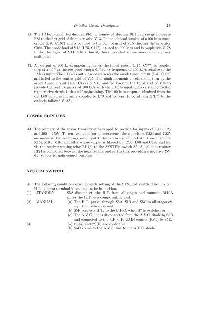
Detailed Circuit Description 26<br />
42. The 1 Mc/s signal, fed through SK2, is connected through PL2 and the grid stopper<br />
R83 to the first grid of the mixer valve V13. The anode load consists of a 100 kc/s tuned<br />
circuit (L70, C167) and is coupled to the control grid of V15 through the capacitor<br />
C168. The anode load of V15 (L75, C<strong>117</strong>) is tuned to 900 kc/s and is coupledvia C178<br />
to the third grid of V13. V15 is heavily biased so that it functions as a frequency<br />
multiplier.<br />
43. An output of 900 kc/s, appearing across the tuned circuit (L75, C177) is coupled<br />
to grid 3 of V13 thereby producing a difference frequency of 100 kc/s relative to the<br />
1 Mc/s input. The 100 kc/s output appears across the anode tuned circuit (L70, C167)<br />
and is fed to the control grid of V15. The ninth harmonic is selected in turn by the<br />
anode tuned circuit (L75, C177) of V15 and fed back to the third grid of V13 to<br />
provide the beat frequency of 100 kc/s with the 1 Mc/s input. This crystal controlled<br />
regenerative circuit is thus self-maintaining. The 100 kc/s output is obtained from the<br />
coil L69 which is mutually coupled to L70 and fed via the octal plug (PL7) to the<br />
cathode-follower V12A.<br />
POWER SUPPLIES<br />
44. The primary of the mains transformer is tapped to provide for inputs of 100 – 125<br />
and 200 – 250V. To remove mains-borne interference the capacitors C224 and C225<br />
are incluced. The secondary winding of T1 feeds a bridge-connected full-wave rectifier<br />
MR4, MR5, MR6 and MR7 whose output is filtered by C206, L80 and C198 and fed<br />
via the receiver muting relay RL1/1 to the SYSTEM switch S5. A 120-ohm resistor<br />
R124 is connected between the negative line and earths thus providing a negative 25V<br />
d.c. supply for gain control purposes.<br />
SYSTEM SWITCH<br />
45. The following conditions exist for each setting of the SYSTEM switch. The link on<br />
H.T. adaptor terminal is assumed to be in position.<br />
(1) STANDBY S5A disconnects the H.T. from all stages and connects R119A<br />
across the H.T. as a compensating load.<br />
(2) MANUAL (a) The H.T. passes through S5A, S5B and S5C to all stages except<br />
the calibration unit.<br />
(b) S5F connects H.T. to the B.F.O. when S7 is switched on.<br />
(c) The A.V.C. line is disconnected from the A.V.C. diode by S5D<br />
and connected to the R.F./I.F. GAIN control (RV1) by S5E.<br />
(3) (a) (2)(a) and (2)(b) are applicable.<br />
(b) S5D connects the A.V.C. line to the A.V.C. diode.


