amp superseal 1,5 series connectors - Produktinfo.conrad.com
amp superseal 1,5 series connectors - Produktinfo.conrad.com
amp superseal 1,5 series connectors - Produktinfo.conrad.com

You also want an ePaper? Increase the reach of your titles
YUMPU automatically turns print PDFs into web optimized ePapers that Google loves.
Product<br />
Specification<br />
108-20090<br />
Rev. C1<br />
Description.<br />
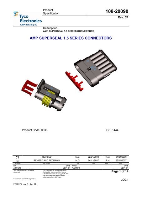
AMP SUPERSEAL 1,5 SERIES CONNECTORS<br />
AMP SUPERSEAL 1,5 SERIES CONNECTORS<br />
Product Code: 0933 GPL: 444<br />
C1 REVISED M.G. 22/01/2008 R.M. 31/01/2008<br />
C REVISED AND REDRAWN M.G. 24/11/2007 R.M. 25/11/2007<br />
rev letter rev. record DR Date CHK Date<br />
DR. DATE APVD DATE<br />
A.BRUNI SEP. ‘91 A.BRUNI SEP. ‘91<br />
Page 1 of 14<br />
This specification is a controlled<br />
document.<br />
* Trademark of AMP Incorporated<br />
FTEC174 rev. 1 - July 99<br />
This information is confidential and is<br />
disclosed to you on condition that no<br />
further disclosure is made by you to other<br />
than AMP personnel without written<br />
authorization from AMP Italia.<br />
LOC I
108-20090<br />
1.0 SCOPE:<br />
This specification covers the requirements for products performance, test methods and quality<br />
assurance provisions of following products:<br />
NR. OF<br />
POSITIONS<br />
FEMALE CONNECTORS<br />
(Housings assemblies for receptacle<br />
contacts, 1 to 6 positions, with<br />
sealing gasket and anti-backout<br />
device which warns if a contact is<br />
not correctly inserted in housing and<br />
doesn’t allow the gasket to slip-off<br />
during the unmating operation)<br />
MALE CONNECTORS<br />
Housings assemblies for tab contacts,<br />
1 to 6 positions, with anti-backout device<br />
which warns when a contact is not correctly<br />
inserted in housing)<br />
1 282079-X 282103-X<br />
2 282080-X 282104-X<br />
3 282087-X 282105-X<br />
4 282088-X 282106-X<br />
5 282089-X 282107-X<br />
6 282090-X 282108-X<br />
WIRE SIZE RANGE<br />
(mm 2 )<br />
MINI-MIC<br />
RECEPTACLE CONTACTS<br />
MINI-MIC<br />
TAB CONTACTS<br />
0.35 – 0.5 282403-X 282404-X<br />
0.75 – 1.5 282110-X 282109-X<br />
1.5 – 2.5 282466-X 282465-X<br />
Single wire seals for both tab and receptacle contacts : 281934-X<br />
Rubber plug to seal unused cavities : 282081-1<br />
Rev. C1 Page 2 of 14<br />
FTEC174 rev. 1 July 99<br />
LOC I
108-20090<br />
REQUIREMENTS:<br />
2.0 DESIGN AND CONSTRUCTION:<br />
Product shall <strong>com</strong>ply with the design, construction and physical dimensions specified in the<br />
applicable product drawing.<br />
2.1 MATERIALS:<br />
Components Material Finish, for<br />
contacts only<br />
Contacts<br />
Receptacle contacts: Phosphor Bronze<br />
Tab contacts: Brass<br />
PreTin plated<br />
Housings / Sec. Lock PA 6.6, Glassfiber filled /<br />
Radial Sealing / Single wire seals Liquid silicone rubber /<br />
2.2 RATINGS:<br />
A. Current Rating : 14A max. with 1,5 mm² wire<br />
B. Temperature Rating: -40°C to +125°C including the temperature increasing due to<br />
working current flow<br />
C. Maximum Operating Voltage: 24 Vd.c.. For application at higher voltage please<br />
contact Tyco Electronics.<br />
D. Protection Degree: IP 67, IPX6K, IP X9K according to IEC 529 and to DIN 40050,<br />
Part 9.<br />
2.3 QUALITY ASSURANCE PROVISION:<br />
A. S<strong>amp</strong>le preparation:<br />
The test s<strong>amp</strong>les to be used for the tests shall be prepared by randomly selecting from<br />
the current production, and the contact crimped in accordance with the Application<br />
Specification 114-20045. No s<strong>amp</strong>le shall be reused, unless otherwise specified.<br />
B. Test Environment:<br />
All the tests shall be performed under any <strong>com</strong>bination of the following test conditions,<br />
unless otherwise specified.<br />
Room temperature: 23 ± 2°C<br />
Relative Humidity: 45÷70%<br />
Atmospheric Pressure: 860÷1060 mbar<br />
Rev. C1 Page 3 of 14<br />
FTEC174 rev. 1 July 99<br />
LOC I
108-20090<br />
3.0 TEST REQUIREMENTS AND PROCEDURES SUMMARY:<br />
3.1<br />
Voltage Drop<br />
FEATURES TEST CONDITIONS LIMITS<br />
(mated <strong>connectors</strong>)<br />
Between two points on wires at<br />
1cm from the housing edges.<br />
Test currents:<br />
6A for 0,5sqmm wire<br />
11A for 1,0sqmm wire<br />
14A for 1,5sqmm wire<br />
≤ 3 mV/A on new contacts.<br />
The voltage drop of wire must<br />
be subtracted<br />
3.2<br />
Contact resistance<br />
3.3<br />
Insulation Resistance<br />
3.4<br />
Dielectric withstanding<br />
voltage<br />
3.5<br />
Connector mating force<br />
(mated contacts)<br />
Between the ends of crimps.<br />
Test current: 10mA<br />
(mated <strong>connectors</strong>)<br />
Between adjacent contacts apply<br />
500 Vd.c. for 1 min.<br />
Between adjacent contacts apply<br />
1500Va.c. for 1 min.<br />
Mate <strong>connectors</strong> with their<br />
contacts loaded at a speed of<br />
25÷100mm/min<br />
≤ 3 mΩ on new contacts.<br />
≥ 200 MΩ<br />
(new contacts)<br />
No breakdown or flashes<br />
1 pos. conn.:<br />
≤ 80N<br />
2÷6 pos. conn.:<br />
≤ 120N<br />
3.6<br />
Connector unmating<br />
force<br />
Unmate <strong>connectors</strong> with their<br />
contacts loaded at a speed of<br />
25÷100mm/min:<br />
a) Without operate the locking<br />
lance<br />
b) Operating the locking lance<br />
a) All positions:<br />
≥ 145N<br />
b) 1 pos. conn.:<br />
≤ 80N<br />
2÷6 pos. conn.:<br />
≤ 120N<br />
Rev. C1 Page 4 of 14<br />
FTEC174 rev. 1 July 99<br />
LOC I
108-20090<br />
FEATURES TEST CONDITIONS LIMITS<br />
3.7<br />
Single contact engaging<br />
force<br />
Engage single rec.ctc. onto tab<br />
counterpart using a free floating<br />
fixture with a rate of 25-<br />
100mm/min of travel speed<br />
(tab as shown in Fig.1)<br />
≤ 8N<br />
3.8<br />
Single contact<br />
disengaging force<br />
3.9<br />
Retention force of the<br />
single contact in the<br />
housings<br />
3.10<br />
Crimping Tensile<br />
Strength<br />
3.11: Corrosion Test<br />
3.11a<br />
Salt spray corrosion<br />
3.11b<br />
Kesternich corrosion<br />
Separate single rec.ctc. from tab<br />
counterpart using a free floating<br />
fixture with a rate of 25-<br />
100mm/min of travel speed<br />
(tab as shown in Fig.1)<br />
Apply an axial force to pull out<br />
contacts from relevant hsg.<br />
cavity using a free floating fixture<br />
with a tensile speed of 50-<br />
70mm/min. with and without antibackout<br />
device<br />
Pull out the contacts from the<br />
relevant wire using a free floating<br />
fixture at a tensile speed of 25 -<br />
100 mm/min.<br />
Subject mated contacts<br />
energized with voltage of<br />
12Vd.c. to 150 hours of salt mist<br />
at 35°C (5% of NaCl)<br />
(single contacts mated in free air)<br />
4 cycles <strong>com</strong>posed of :<br />
- 8 hrs. of exposure to an<br />
atmosphere with 0.66% of SO2<br />
at 40±2°C and 95% humidity<br />
- 16 hrs in free air.<br />
(single contacts mated in free air)<br />
≥ 2,5N<br />
Without anti-backout device:<br />
≥ 80N<br />
With anti-backout device:<br />
≥ 90 N<br />
0.35sqmm wires: > 60N<br />
0,5sqmm wires: > 70N<br />
1,0sqmm wires: > 115N<br />
1,5sqmm wires: > 155N<br />
Voltage drop ≤ 5mV/A<br />
Rev. C1 Page 5 of 14<br />
FTEC174 rev. 1 July 99<br />
LOC I
108-20090<br />
FEATURES TEST CONDITIONS LIMITS<br />
3.12<br />
Water resistance:<br />
Static immersion<br />
3.13<br />
Water resistance:<br />
Dynamic immersion<br />
3.14<br />
Water resistance:<br />
IP X6K Test<br />
Mated <strong>connectors</strong> subjected to 5<br />
cycles <strong>com</strong>posed of:<br />
- 30 min. in oven at +125°C<br />
- 30 min. immersed in water with<br />
5% of NaCl under a pressure of<br />
0,01bar at a temperature of 23°C<br />
Mated <strong>connectors</strong> immersed in<br />
water with 5% on NaCl, under a<br />
pressure of 0,01bar at a<br />
temperature of 23°C.<br />
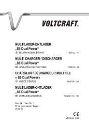
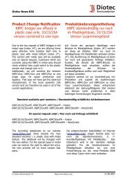
Wire pulled with a force of<br />
1,5÷2,5N oscillated 100.000<br />
times (as per Fig. 2).<br />
Oscillation frequency:<br />
50cycles/min.<br />
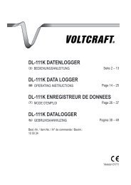
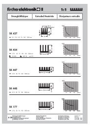
Test according to DIN 40050,<br />
Part 9.<br />
Duration: 3min. minimum<br />
Subject mated <strong>connectors</strong><br />
<strong>com</strong>pletely loaded with terminals<br />
to water jet with following<br />
parameters:<br />
nozzle:6.3mm dia<br />
pressure: 1000kPa<br />
-Insulation resistance: ≥200MΩ<br />
-No leakage detected to a<br />
visual examination<br />
-Insulation resistance: ≥200MΩ<br />
-No leakage detected to a<br />
visual examination<br />
-Insulation resistance as above<br />
specified.<br />
-No leakage detected to a<br />
visual examination<br />
3.15<br />
Water resistance:<br />
IP X9K Test<br />
(test setup as per Fig. 4)<br />
Test according to DIN 40050,<br />
Part 9.<br />
Duration: 30s for each nozzle.<br />
Subject mated <strong>connectors</strong><br />
<strong>com</strong>pletely loaded with terminals<br />
to the cumulative action of the<br />
four nozzles.<br />
(test setup as per Fig. 5)<br />
-Insulation resistance and<br />
dielectric withstanding voltage<br />
as above specified.<br />
-No leakage detected to a<br />
visual examination<br />
Rev. C1 Page 6 of 14<br />
FTEC174 rev. 1 July 99<br />
LOC I
108-20090<br />
FEATURES TEST CONDITIONS LIMITS<br />
3.16<br />
Thermal cycling<br />
Mated <strong>connectors</strong> subjected to:<br />
- 14 cycles <strong>com</strong>posed of:<br />
• 16 hours at +40°C, 95% r.h.<br />
• 2 hours at -40°C<br />
• 2 hours at +125°C<br />
• 4 hours at +23°C<br />
(max.time to change condition:<br />
3min.)<br />
- exposure for 24 hours at +40°C<br />
and 95% r.h.<br />
- 10 mating and unmating<br />
operations<br />
- No damages<br />
- Insulation resistance and<br />
dielectric withstanding<br />
resistance as above specified.<br />
- Voltage drop ≤ 5mV/A<br />
- Contact retention in housing,<br />
mating/unmating forces as<br />
above specified<br />
3.17<br />
Ageing resistance<br />
3.18<br />
Chemical resistance<br />
3.19<br />
Ozone gas resistance<br />
Mated <strong>connectors</strong> subjected to:<br />
- 100 hours at +125°C<br />
- 10 mating/unmating operations<br />
Mated <strong>connectors</strong> immersed for<br />
3 min. in:<br />
- Brake fluid at +50°C<br />
- Anti-freeze fluid at +23°C<br />
- Transmission and engine oil<br />
at +100°C<br />
- Gasoline at +23°C<br />
- Diesel fuel at +23°C<br />
- Window cleaner at +23°C<br />
Mated <strong>connectors</strong> exposed for<br />
70 hours at an atmosphere with<br />
0,5ppM of ozone at 50°C<br />
- No damages<br />
- Insulation resistance and<br />
dielectric withstanding<br />
resistance as above specified<br />
- Voltage drop ≤ 5mV/A<br />
- Contact retention in housing,<br />
mating/unmating forces as<br />
above specified<br />
- No damages<br />
- No leakages detected at<br />
visual examination<br />
- Contact retention in housing,<br />
mating/unmating forces as<br />
above specified<br />
- No damages<br />
- Contact retention in housing,<br />
mating/unmating forces as<br />
above specified<br />
Rev. C1 Page 7 of 14<br />
FTEC174 rev. 1 July 99<br />
LOC I
108-20090<br />
3.20<br />
Vibration Test<br />
FEATURES TEST CONDITIONS LIMITS<br />
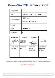
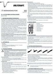
Mated <strong>connectors</strong> placed on a<br />
platform as per Fig.3, subjected<br />
to vibrations with following<br />
parameters:<br />
- Frequency: 10 - 500 - 10Hz<br />
- Speed of frequency variation:<br />
1octave/min.<br />
- Displacement: 0,75mm for<br />
frequencies below 70Hz.<br />
Over 70Hz maintain a constant<br />
acceleration of 150m/s 2<br />
- Duration: 2hours each axis<br />
- 10 cycles mating/unmating<br />
- No damages<br />
- Dielectric withstanding<br />
resistance as above specified<br />
- Voltage drop ≤ 5mV/A<br />
- Contact retention in housing,<br />
mating/unmating forces as<br />
above specified<br />
- No circuit break greater than<br />
1µs<br />
3.21<br />
High temperature<br />
resistance with current<br />
load<br />
3.22<br />
Current overload<br />
3.23<br />
Durability<br />
Mated <strong>connectors</strong> subjected to a<br />
temperature of 80°C for 5 hours<br />
with all contacts loaded with<br />
max.current of 14A (1,5sqmm<br />
wires)<br />
Mated <strong>connectors</strong> subjected to<br />
500 cycles with current of 21A<br />
(1,5sqmm wires).<br />
Each cycle <strong>com</strong>posed of:<br />
- 45 min. current ON<br />
- 15 min. current OFF<br />
Mate-unmate 10 times the tabs<br />
of Fig.1 at a constant speed of<br />
25÷100mm/min.<br />
Max. increase of temperature<br />
detected on transition between<br />
contact body and wire barrel:<br />
50°C<br />
Max. increase of temperature<br />
detected on transition between<br />
contact body and wire barrel:<br />
60°C<br />
Voltage drop: ≤ 3mV/A<br />
Contact resistance: ≤ 3mΩ<br />
NOTE: SEE NEXT PAGE FOR TEST GROUPS AND SEQUENCE.<br />
Rev. C1 Page 8 of 14<br />
FTEC174 rev. 1 July 99<br />
LOC I
108-20090<br />
NUM.<br />
TEST DESCRIPTION<br />
3.0 VISUAL EXAMINATION<br />
GROUPS AND SEQUENCE<br />
A B C D E F G H I L M N O P Q R<br />
1,<br />
11<br />
3.1 VOLTAGE DROP 4, 9<br />
3.2 CONTACT RESISTANCE 5, 1<br />
3.3<br />
INSULATION<br />
RESISTANCE<br />
DIELECTRIC<br />
3.4 WITHSTANDING<br />
VOLTAGE<br />
3.5<br />
CONNECTOR MATING<br />
FORCE<br />
3.6<br />
CONNECTOR UNMATING<br />
FORCE<br />
3.7 CTC. ENGAGING FORCE 2, 7<br />
1 1<br />
1,<br />
5<br />
2,<br />
4<br />
3.8<br />
CTC. DISENGAGING<br />
FORCE<br />
3, 8<br />
3.9<br />
CONTACT RETENTION IN<br />
5,<br />
4, 4, 4,<br />
2<br />
HSG.<br />
16<br />
11 15 8<br />
4, 9<br />
3.10<br />
CRIMP TENSILE<br />
STRENGHT<br />
2<br />
3.11a<br />
SALT SPRAY<br />
CORROSION<br />
3<br />
3.11b<br />
KESTERNICH<br />
CORROSION<br />
3<br />
3.12 STATIC IMMERSION 3<br />
3.13 DYNAMIC IMMERSION<br />
10<br />
6<br />
(**)<br />
(**)<br />
3<br />
3.14 IP X6K TEST 3<br />
1,<br />
5<br />
2,<br />
4<br />
3.15 IP X9K TEST 4<br />
3.16 THERMAL CYCLING 8<br />
3.17 AGEING RESISTANCE 8<br />
3.18 CHEMICAL RESISTANCE 5<br />
1,<br />
17<br />
4,<br />
13<br />
6,<br />
11<br />
7,<br />
12<br />
2,<br />
15<br />
3,<br />
14<br />
3.19<br />
OZONE GAS<br />
RESISTANCE<br />
3.20 VIBRATION TEST 6<br />
HIGH TEMP. RESISTANCE<br />
3,21<br />
3<br />
W. CURRENT LOAD<br />
3.22 CURRENT OVERLOAD 3<br />
3.23 DURABILITY 6 9 7 9<br />
1,<br />
5<br />
2,<br />
4<br />
1,5<br />
2,<br />
4<br />
1,<br />
12<br />
5, 8<br />
2,<br />
10<br />
3, 9<br />
1,<br />
5<br />
2,<br />
4<br />
1,<br />
16<br />
5,<br />
12<br />
6,<br />
10<br />
7,<br />
11<br />
2,<br />
14<br />
3,<br />
13<br />
1,<br />
9<br />
2,<br />
7<br />
3,<br />
6<br />
1,<br />
10<br />
2, 8<br />
3, 7<br />
5<br />
1,<br />
5<br />
2,<br />
4<br />
1,<br />
5<br />
2,<br />
4<br />
1,<br />
7<br />
2,<br />
5<br />
3,<br />
6<br />
(**) : 10.000 CYCLES ONLY<br />
Rev. C1 Page 9 of 14<br />
FTEC174 rev. 1 July 99<br />
LOC I
108-20090<br />
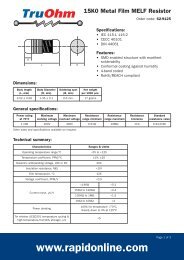
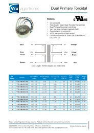
TEST TAB DIMENSIONS<br />
FIG. 1<br />
Rev. C1 Page 10 of 14<br />
FTEC174 rev. 1 July 99<br />
LOC I
108-20090<br />
DYNAMIC IMMERSION TEST SETUP<br />
FIG. 2<br />
Rev. C1 Page 11 of 14<br />
FTEC174 rev. 1 July 99<br />
LOC I
108-20090<br />
VIBRATION TEST SETUP<br />
FIG. 3<br />
Rev. C1 Page 12 of 14<br />
FTEC174 rev. 1 July 99<br />
LOC I
108-20090<br />
IP X6K TEST SETUP<br />
FIG. 4<br />
Rev. C1 Page 13 of 14<br />
FTEC174 rev. 1 July 99<br />
LOC I
108-20090<br />
IP X9K TEST SETUP<br />
FIG. 5<br />
Rev. C1 Page 14 of 14<br />
FTEC174 rev. 1 July 99<br />
LOC I