3ST sales bulletin - F W Murphy
3ST sales bulletin - F W Murphy
3ST sales bulletin - F W Murphy

You also want an ePaper? Increase the reach of your titles
YUMPU automatically turns print PDFs into web optimized ePapers that Google loves.
<strong>3ST</strong><br />
Three point speed relay<br />
ms5885<br />
(supersedes ms5884 / M040301)<br />
revision D, 20th March 2003<br />
catalogue section 20<br />
• Three speed relays<br />
in one compact unit<br />
• Wide operating frequency<br />
• Engine RPM meter output<br />
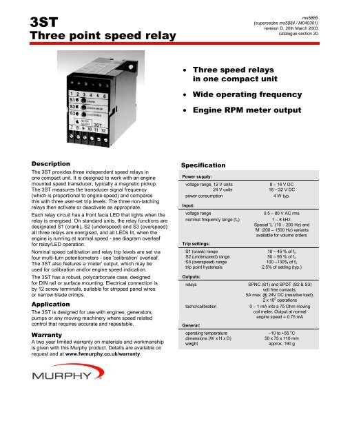
Description<br />
The <strong>3ST</strong> provides three independent speed relays in<br />
one compact unit. It is designed to work with an engine<br />
mounted speed transducer, typically a magnetic pickup.<br />
The <strong>3ST</strong> measures the transducer signal frequency<br />
(which is proportional to engine speed) and compares<br />
this with three user-set trip levels. The three non-latching<br />
relays then activate or deactivate as appropriate.<br />
Each relay circuit has a front facia LED that lights when the<br />
relay is energised. On standard units, the relay functions are<br />
designated S1 (crank), S2 (underspeed) and S3 (overspeed):<br />
all three relays are energised, and all LEDs lit, when the<br />
engine is running at normal speed - see diagram overleaf<br />
for relay/LED operation.<br />
Nominal speed calibration and relay trip levels are set via<br />
four multi-turn potentiometers - see ‘calibration’ overleaf.<br />
The <strong>3ST</strong> also features a ‘meter’ output, which may be<br />
used for calibration and/or engine speed indication.<br />
The <strong>3ST</strong> has a robust, polycarbonate case, designed<br />
for DIN rail or surface mounting. Electrical connection is<br />
by 12 screw terminals, suitable for stripped panel wires<br />
or narrow blade crimps.<br />
Application<br />
The <strong>3ST</strong> is designed for use with engines, generators,<br />
pumps or any moving machinery where speed related<br />
control that requires accurate and repeatable.<br />
Warranty<br />
A two year limited warranty on materials and workmanship<br />
is given with this <strong>Murphy</strong> product. Details are available on<br />
request and at www.fwmurphy.co.uk/warranty.<br />
Specification<br />
Power supply:<br />
voltage range, 12 V units<br />
8 – 16 V DC<br />
24 V units 16 – 32 V DC<br />
power consumption<br />
4 W typ.<br />
Input:<br />
voltage range<br />
nominal frequency range (f o)<br />
Trip settings:<br />
S1 (crank) range<br />
S2 (underspeed) range<br />
S3 (overspeed) range<br />
trip point hysteresis<br />
Outputs:<br />
0.5 – 80 V AC rms<br />
1 – 8 kHz.<br />
Special ‘L’ (10 – 200 Hz) and<br />
’M’ (200 – 1500 Hz) variants<br />
available for volume orders<br />
10 – 45 % of f o<br />
50 – 95 % of f o<br />
100 –130% of f o<br />
2.5% of setting (typ.)<br />
relays SPNC (S1) and SPDT (S2 & S3)<br />
volt free contacts,<br />
5A max. @ 24V DC (resistive load),<br />
2 x 10 5 operations<br />
tacho/calibration<br />
0 – 1 mA into a 75 Ohm moving<br />
coil meter. Output at normal<br />
engine speed = 0.75 mA<br />
General:<br />
operating temperature<br />
dimensions (W x H x D)<br />
weight<br />
–10 to +55 o C<br />
50 x 75 x 110 mm<br />
approx. 190 g
Relay operation/LED indication<br />
Electrical connection<br />
under<br />
speed<br />
crank<br />
+ ve DC<br />
– ve DC<br />
mag. pickup<br />
or transducer<br />
engine<br />
flywheel<br />
Dimensions<br />
How to order<br />
1 2 3 4 5 6<br />
7<br />
8<br />
9<br />
over<br />
speed<br />
<strong>3ST</strong><br />
10<br />
11<br />
12<br />
0 - 1mA, 75 Ohm<br />
moving coil meter<br />
(link out 10 and 11<br />
if meter is not used)<br />
Stock Units<br />
These are supplied with blank calibration labels and set to a<br />
nominal frequency (fo) of 3000Hz (equivalent to 120 flywheel<br />
teeth at 1500 RPM). These units will usually therefore require<br />
customer calibration:-<br />
Stock code Model / description<br />
76.70.0039 <strong>3ST</strong>/1SET4 speed trip, 24V, std. settings<br />
76.70.0068 <strong>3ST</strong>/2SET4 speed trip, 12V, std. settings<br />
Special Calibration<br />
We can also supply the <strong>3ST</strong> calibrated to your requirements.<br />
Please specify:-<br />
a) Model type: <strong>3ST</strong>/1 (24V) or <strong>3ST</strong>/2 (12V)<br />
b) Nominal transducer frequency (fo)<br />
c) Trip levels for S1, S2 and S3, expressed as either:<br />
i) an absolute (transducer) trip frequency (in Hz), or<br />
ii) a percentage of fo<br />
Calibration<br />
For the <strong>3ST</strong> to correctly measure engine speed, it must<br />
be calibrated for each particular engine and transducer type.<br />
Calibration may be carried out during engine commissioning,<br />
or ‘on the bench’ using a signal generator to simulate the<br />
engine speed transducer. This is a two stage process:-<br />
a) Nominal calibration<br />
Use the METER ADJUST potentiometer to calibrate<br />
the <strong>3ST</strong> to the ‘nominal’ transducer frequency (or fo, the<br />
transducer output frequency when the engine is running<br />
at normal speed). Standard units allow adjustment of fo<br />
between 1 and 8 kHz.<br />
When calibrating with a signal generator, fo must be known,<br />
either a) by prior measurement of the pickup when the engine<br />
is running, or b) by calculation - e.g. for a pickup and flywheel:-<br />
fo (Hz) = normal engine speed x number of flywheel teeth<br />
60<br />
To set the nominal calibration:-<br />
• Connect the pickup, transducer or signal generator input:<br />
signal positive to pin 9, signal negative to pin 10<br />
• Connect a 0 – 1mA meter (ideally with a 75 ohm moving<br />
coil action): meter positive to pin 11, meter negative to<br />
pin 10.<br />
• Connect the DC power supply: positive DC to pin 12,<br />
negative DC to pin 10. Switch on the supply.<br />
• Start the engine manually (not under the control of the<br />
<strong>3ST</strong> relays) and run to normal speed, or adjust the<br />
signal generator to simulate the transducer signal.<br />
• Turn the METER ADJUST potentiometer until the meter<br />
reads 0.75mA. Turn the pot. clockwise to increase the<br />
meter reading (i.e. to lower the nominal calibration<br />
frequency). All LEDs should now be lit.<br />
The nominal calibration is now complete. The meter may<br />
be left connected to the <strong>3ST</strong> or replaced with a wire link.<br />
b) S1, S2 and S3 relay settings<br />
Once the nominal calibration (fo) has been set, use<br />
potentiometers S1, S2 and S3 to set the trip frequency<br />
of each relay. The adjustment range of each pot. is fixed<br />
in percentage terms to fo (see specification for ranges);<br />
the absolute frequency range and setting of each relay<br />
will therefore change if fo is changed.<br />
For each of the 3 relay settings:-<br />
• Adjust the engine speed to the required trip level, or<br />
adjust the signal generator to simulate the transducer<br />
frequency at the required engine speed.<br />
• Adjust the potentiometer (S1, S2 or S3) until the relay<br />
just changes over (the LED will light then extinguish).<br />
Turn each pot clockwise to increase the trip frequency.<br />
The <strong>3ST</strong> is now calibrated. For full details of <strong>3ST</strong> calibration,<br />
please see our separate installation instructions<br />
FW <strong>Murphy</strong><br />
PO Box 470248<br />
Tulsa, Oklahoma 74147, USA<br />
tel: +1 918 317 4100<br />
fax: +1 918 317 4266<br />
email: <strong>sales</strong>@fwmurphy.com<br />
web: www.fwmurphy.com<br />
CONTROL SYSTEMS AND SERVICES DIVISION<br />
PO Box 1819, Rosenberg, Texas 77471, USA<br />
tel: +1 281 633 4500<br />
fax: +1 281 633 4588<br />
email: <strong>sales</strong>@fwmurphy.com<br />
MURPHY DE MEXICO S.A. DE C.V.<br />
Blvd. Antonio Rocha Cordero 300, Fracción del Aguaje<br />
San Luis Potosí, S.L.P. México 78384<br />
tel: +52 444 8206264<br />
fax: +52 444 8206336<br />
Villahermosa office tel: +52 993 3162117<br />
email: ventasmex@murphymex.com.mx<br />
web: www.murphymex.com.mx<br />
FRANK W. MURPHY LTD.<br />
Church Rd, Laverstock, Salisbury, SP1 1QZ, UK<br />
tel: +44 1722 410055<br />
fax: +44 1722 410088<br />
email: <strong>sales</strong>@fwmurphy.co.uk<br />
web: www.fwmurphy.co.uk<br />
MURPHY SWITCH OF CALIFORNIA<br />
41343 12th Street West,<br />
Palmdale, CA 93551-1442, USA<br />
tel: +1 661 272 4700<br />
fax: +1 661 947 7570<br />
email: <strong>sales</strong>@murphyswitch.com<br />
web: www.murphyswitch.com<br />
MACQUARRIE CORPORATION<br />
1620 Hume Highway,<br />
Campbellfield, Victoria 3061, Australia<br />
tel: +61 3 9358 5555<br />
fax: +61 3 9358 5558<br />
email: murphy@macquarrie.com.au<br />
In order to consistently bring you the highest quality, full featured products, we reserve the right to change our specifications and designs at any time.