3D Tumor Shape Reconstruction from 2D Bioluminescence Images
3D Tumor Shape Reconstruction from 2D Bioluminescence Images
3D Tumor Shape Reconstruction from 2D Bioluminescence Images

You also want an ePaper? Increase the reach of your titles
YUMPU automatically turns print PDFs into web optimized ePapers that Google loves.
<strong>3D</strong> TUMOR SHAPE RECONSTRUCTION FROM <strong>2D</strong> BIOLUMINESCENCE IMAGES<br />
Junzhou Huang, Xiaolei Huang, Dimitris Metaxas<br />
CBIM, DCIS,<br />
Rutgers University, NJ, USA<br />
Debarata Banerjee<br />
Cancer Institute of New Jersey,<br />
UMDNJ, NJ, USA<br />
ABSTRACT<br />
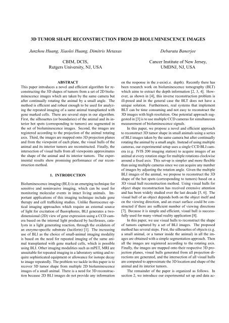
This paper introduces a novel and efficient algorithm for reconstructing<br />
the <strong>3D</strong> shapes of tumors <strong>from</strong> a set of <strong>2D</strong> bioluminescence<br />
images which are taken by the same camera but<br />
after continually rotating the animal by a small angle. The<br />
method is efficient and robust enough to be used for analyzing<br />
the repeated imaging of a same animal transplanted with<br />
gene marked cells. There are several steps in our algorithm.<br />
First, the silhouettes (or boundaries) of the animal and its interior<br />
hot spots (corresponding to tumors) are segmented in<br />
the set of bioluminescence images. Second, the images are<br />
registered according to the projection of the animal rotating<br />
axis. Third, the images are mapped onto <strong>3D</strong> projection planes<br />
and <strong>from</strong> the viewpoint of each plane, the visual hulls of the<br />
animal and its interior tumors are reconstructed. Finally, the<br />
intersection of visual hulls <strong>from</strong> all viewpoints approximates<br />
the shape of the animal and its interior tumors. The experimental<br />
results show promising performance of our reconstruction<br />
method.<br />
1. INTRODUCTION<br />
<strong>Bioluminescence</strong> imaging (BLI) is an emerging technique for<br />
sensitive and noninvasive imaging, which can be used for<br />
monitoring molecular events in intact living animals. Important<br />
applications of this imaging technique include gene<br />
therapy and cell trafficking studies. Unlike fluorescence optical<br />
imaging approaches which require an external source<br />
of light for excitation of fluorophores, BLI generates a twodimensional<br />
(<strong>2D</strong>) view of gene expression using a CCD camera<br />
based on the internal light produced by luciferases, catalysts<br />
in a light generating reaction, through the oxidation of<br />
an enzyme-specific substrate (luciferin) [1]. The increasing<br />
use of BLI as the choice of small-animal imaging modality<br />
is based on the need for repeated imaging of the same animal<br />
transplanted with gene marked cells, which is possible<br />
using BLI. Other imaging modalities such as mPET, MRI are<br />
unsuitable for repeated imaging in a laboratory setting and require<br />
sophisticated equipment or allowance for isotope decay<br />
to image repeatedly. The problem we tackle in this paper is to<br />
recover <strong>3D</strong> tumor shape <strong>from</strong> multiple <strong>2D</strong> bioluminescence<br />
images of a small animal. There is a need for <strong>3D</strong> reconstruction<br />
because <strong>2D</strong> BLI images do not provide any information<br />
on the response in the z-axis(i.e. depth). Recently there has<br />
been research work on bioluminescence tomography (BLT)<br />
which aims to extract the depth information [2, 3, 4]. However,<br />
as shown in [4], this inverse reconstruction problem is<br />
ill-posed and in the general case the BLT does not have a<br />
unique solution. Furthermore, real systems that implement<br />
BLT can be time consuming and not easy to reconstruct the<br />
<strong>3D</strong> images with high resolution. One potential approach suggested<br />
in [3] is to use multiple CCD cameras for simultaneous<br />
measurement of bioluminescence signals.<br />
In this paper, we propose a novel and efficient approach<br />
to reconstruct <strong>3D</strong> tumor shape in small animals using a series<br />
of BLI images taken by the same camera but after continually<br />
rotating the animal by a small angle. Instead of using multiple<br />
cameras, our experimental setup uses a single CCD BLI camera<br />
(e.g. IVIS 200 imaging station) to acquire images of an<br />
animal at every rotation stage for multiple rotations clockwise<br />
around a fixed axis. This set-up is simpler and more flexible<br />
than using multiple cameras since we can acquire any number<br />
of images by adjusting the rotation angle. Given the multiple<br />
BLI images of the animal, we propose to reconstruct the <strong>3D</strong><br />
shape of the hot spots (corresponding to tumors) based on a<br />
<strong>3D</strong> visual hull reconstruction method. Using visual hulls for<br />
object shape reconstruction has received extensive attention<br />
and has been widely studied over the last decade [5, 6]. The<br />
visual hull of an object depends both on the object itself and<br />
on the viewing direction, and an exact surface could be constructed<br />
if there are sufficient number of viewing directions<br />
[7]. Because it is simple and efficient, visual hull is successfully<br />
used for many virtual reality application [8].<br />
In this paper, we use visual hulls to reconstruct the shape<br />
of tumors captured by a set of BLI images. The proposed<br />
method has several steps. First, the silhouettes of objects (e.g.<br />
a small animal, or a tumor inside the animal) in all the images<br />
are obtained with a simple segmentation approach. Then<br />
all the images are registered according to the rotating axis.<br />
Finally, the images are mapped onto their respective <strong>3D</strong> projection<br />
planes, visual hulls generated <strong>from</strong> all projection directions<br />
are generated, and the intersection of all visual hulls<br />
are computed to approximate the <strong>3D</strong> location and shape of the<br />
animal and its interior tumors.<br />
The remainder of the paper is organized as follows. In<br />
section 2, we introduce our experimental set up and data ac-
Fig. 1. Examples of BLI images acquired <strong>from</strong> a small animal<br />
with tumor cells growing in the abdomen.<br />
quisition method. Section 3 presents the procedures for segmenting<br />
animal tumor silhouettes. Section 4 introduces the<br />
method for registering images. The visual hull reconstruction<br />
algorithm and experimental results using both a phantom<br />
study and real small-animal images are presented in section<br />
5. Section 6 concludes this paper with discussions.<br />
(1)<br />
(2)<br />
(3)<br />
2. SETUP AND IMAGE ACQUISITION<br />
The bioluminescence images were acquired following injection<br />
of D-luciferin (given i.p. at 150mg/ml) and image reconstruction<br />
was carried out using manufacturer’s (the IVIS<br />
100 machine, by Xenogen, Alameda, CA) software. <strong>Images</strong><br />
were acquired in a standard mode with 2x2 binning. In order<br />
to get specificity of the response in the z-axis, we design the<br />
following experimental set up.<br />
The animal to be imaged is inserted into a cylindrical 50<br />
ml tube cut at both ends that can be rotated by a small angle<br />
(12 degrees) at a time <strong>from</strong> the vertical axis. <strong>Images</strong> are<br />
acquired at every rotation stage clockwise <strong>from</strong> the vertical<br />
axis. This generates a series of images including the one without<br />
any rotation. Fig.1 shows some example BLI images of<br />
a mouse with tumor in the abdomen area. The mouse is contained<br />
in a 50 ml tube cut at both ends and bottoms. The tumor<br />
regions have higher intensity values in the BLI images. The<br />
dimensions along long axis and short axis of the mouse tumor<br />
is 1.2cm, 1.1cm and 1.1cm, which is obtained by sacrificing<br />
mouse after image capturing.<br />
In the following sections, we also use a set of images<br />
<strong>from</strong> a phantom study (Fig.2(1)). The images were generated<br />
by rotating a 50 ml tube clockwise at an increment of<br />
11.25 degrees. Luciferase-positive cell lysates were embedded<br />
in agarose inside the tube. The dimensions along long<br />
axis and short axis of the cluster of lysates are 1.8cm, 1.2cm<br />
and 1.1cm. It appeared as a hot point in images which were<br />
acquired over 20 minutes following injection of D-luciferin.<br />
3. SEGMENTING IMAGES<br />
A visual hull depends both on the object silhouettes and on<br />
the camera viewing direction. Before the reconstruction, we<br />
should obtain the object silhouettes in the images. In our experiment,<br />
as shown in Fig. 2(1), the objects were rotated gradually<br />
with a small angle and their bioluminescence images<br />
were captured correspondingly. Considering that the images<br />
include not only the interested objects (the tube and the tumor),<br />
but also the un-interested background, the captured BLI<br />
(1)<br />
(2)<br />
Fig. 2. Segmentation Examples. (1) BLI images. (2) Segmented<br />
tubes. (3) Segmented tumors<br />
Fig. 3. Registering examples. (1) BLI images. (2) after alignment.<br />
images should be segmented for later processing. In order to<br />
facilitate correct segmentation, a monochromatic background<br />
was captured to distinguish the tube containing the small animal<br />
<strong>from</strong> the environment in the experiment setup. First,<br />
the contour (or silhouette) of the tube containing the small<br />
animal is easily extracted <strong>from</strong> the input images by simple<br />
thresholding. Fig. 2(2) shows the tube segmentation result<br />
we obtained. Then, according to the characteristic of tumor<br />
in the BLI images (they appear as higher intensities), we can<br />
segment the tumor <strong>from</strong> the tube region by combining tumor<br />
intensity and edge information. Fig. 2(3) shows segmentation<br />
results of the tumor in the images.<br />
4. REGISTERING IMAGES<br />
Due to noise in the imaging system during the rotation of the<br />
small animal, the bioluminescence images may not be perfectly<br />
aligned. To ensure accurate correspondence across images,<br />
we apply an image-based method to register the images<br />
such that projections of the rotating axis on all images overlap<br />
in the image space. For this purpose, we define an im-
age dissimilarity objective function based on mutual information<br />
[9, 10], and recover the translation and rotation parameters<br />
by minimizing the objective function. Suppose a source<br />
image is f, and its adjacent target image is g. In the most<br />
general case, let us consider a sample domain Ω in the image<br />
domain of the source image f, we aim to recover the<br />
parameters Θ = (T x , T y , θ) of a global transformation A<br />
such that the mutual information between f Ω = f(Ω) and<br />
gΩ<br />
A = g( A(Θ; Ω) ) is maximized. Here the parameters T x<br />
and T y are translation parameters in the x and y directions<br />
respectively, and θ denotes the rotation angle. And the definition<br />
for such mutual information is:<br />
MI(X f Ω<br />
, X gA Ω<br />
) = H<br />
[<br />
X f Ω<br />
]<br />
+ H<br />
[<br />
X gA Ω<br />
] [ ]<br />
− H X f Ω,gΩ<br />
A<br />
In the above formula, X denotes the intensity random variable<br />
and H represents the differential entropy. Then we define<br />
the image dissimilarity objective function as:<br />
(1)<br />
E(A(Θ)) = −MI(X fΩ , X gA Ω ) (2)<br />
Hence by minimizing this objective function E, we achieve<br />
maximizing mutual information. The calculus of variations<br />
with a gradient descent method is then used to minimize E<br />
and recover the transformation parameters T x , T y and θ. Fig.<br />
3(2) shows the registered images. Note that small displacements<br />
and rotations between consecutive images are corrected.<br />
5. RECONSTRUCTING <strong>3D</strong> TUMOR SHAPE<br />
As introduced above, instead of setting up an image-capturing<br />
system with multiple cameras, we take bioluminescence pictures<br />
by a single fixed camera while rotating the object (tube<br />
or small animal). This setup is equivalent to having multiple<br />
cameras surrounding a static object, but it is much simpler<br />
and does not require calibrating multiple cameras. Fig. 4<br />
demonstrates the multi-view set up where the planes represent<br />
the projection planes for images taken <strong>from</strong> different views.<br />
Since the depth variation due to the object is small compared<br />
with the distance between the animal and the camera, changes<br />
in the object silhouette along the depth direction are negligible.<br />
Thus, an orthographic projection model is reasonable to<br />
use in order to reconstruct the <strong>3D</strong> object structure and tumor<br />
shape. The reconstruction is based on the concept of visual<br />
hull. Formally, the visual hull of an object S with respect<br />
to the viewing region R, denoted by V H(S, R), is a volume<br />
in space such that for each point P in V H(S, R) and each<br />
viewpoint V in R, the half-line <strong>from</strong> V through P contains<br />
at least one point of S [5]. This definition simply states that<br />
the visual hull consists of all points in space whose images lie<br />
within all silhouettes viewed <strong>from</strong> the viewing region. Stated<br />
another way, the visual hull is the maximal object that has the<br />
same silhouettes as the original object, as viewed <strong>from</strong> the<br />
viewing region. In our implementation, because we use the<br />
orthographic projection model, the segmented object and tumor<br />
silhouettes are projected into the <strong>3D</strong> space by cylindrical<br />
(a)<br />
Fig. 4. Setting up projection plane geometry for images taken<br />
<strong>from</strong> different views. (a) some example views for consecutive<br />
images. (b) all views forming a full circle.<br />
visual hulls, instead of conical visual hulls in the projective<br />
projection model. By computing the intersection of the visual<br />
hulls projected <strong>from</strong> all images (i.e. all viewing directions),<br />
we obtain the estimation for the shape and location of the animal<br />
and its interior tumors.<br />
5.1. Experimental Results<br />
First, we perform several phantom studies. Fig. 5(a) demonstrates<br />
the process of determining the <strong>3D</strong> depth of feature<br />
points by computing the intersection of <strong>3D</strong> rays passing perpendicularly<br />
through corresponding feature points on two consecutive<br />
images, which are mapped onto their respective projection<br />
planes. It shows the reconstructed <strong>3D</strong> location of the<br />
tube center (the intersection of the two rays in blue) and the<br />
<strong>3D</strong> location of the tumor center (the intersection of the two<br />
rays in red). The tumor centers on the bioluminescence images<br />
are computed as the centroids of the high-intensity signal<br />
regions (drawn as asterisks on the image planes), and the intersection<br />
of <strong>3D</strong> rays passing through tumor center locations<br />
on images taken <strong>from</strong> different views gives us the location of<br />
the tumor center in <strong>3D</strong>. Fig. 5(b) shows the intersection of<br />
multiple cylindrical hulls based on the tumor silhouettes. The<br />
intersection of all cylindrical hulls gives the <strong>3D</strong> reconstruction<br />
of the tumor shape. In the phantom study, since the object<br />
surface can be approximated using a cylinder, we determine<br />
the radius of the cylinder using silhouettes of the tube. Fig. 6<br />
shows the reconstructed <strong>3D</strong> tumor viewed in two directions.<br />
Fig. 7 shows the reconstructed shape of the tube and tumor,<br />
which are viewed in two different directions.<br />
We also do the same procedures to reconstruct animal and<br />
tumor shapes <strong>from</strong> small-animal BLI images. Fig. 8(a-b)<br />
shows the reconstructed tumor location and shape <strong>from</strong> a set<br />
of BLI images of the mouse with abdominal tumor.<br />
Based on our approach, we establish the relationship between<br />
the reconstructed animal dimension measurements in<br />
the animal centered reference frame and that in the physical<br />
world. This is achieved by computing the conversion ratio<br />
based on one base measurement, such as the diameter or the<br />
length of the tube or mouse).<br />
(b)
−500<br />
500<br />
0<br />
−500<br />
−600<br />
−400<br />
−200<br />
0<br />
200<br />
400<br />
600<br />
500<br />
400<br />
300<br />
200<br />
100<br />
0<br />
−100<br />
−200<br />
−300<br />
−400<br />
(a)<br />
(b)<br />
Fig. 5. (a) Line intersection. (b) Cylinder hull intersection.<br />
(a)<br />
Fig. 7. Reconstructed <strong>3D</strong> tumor (red) in the tube (gray) in the<br />
phantom study, <strong>from</strong> two views<br />
(b)<br />
(a)<br />
(b)<br />
Fig. 6. Reconstructed <strong>3D</strong> tumor shape <strong>from</strong> two views.<br />
5.2. Evaluation<br />
Evaluation of the reconstruction accuracy is done by comparing<br />
the recovered <strong>3D</strong> shape and location of the tumor with the<br />
ground truth in our experimental set up.<br />
In the phantom study, we measured physically the tumor<br />
center location, and dimensions along the long axis and short<br />
axis of the cluster of luciferase-positive cell lysates that appeared<br />
as hot (or bright) spots in the images. Comparing our<br />
reconstruction result with the ground truth (Detailed in section<br />
2), the distance in <strong>3D</strong> between the measured hot spot<br />
center and the reconstructed center is around 2mm, the difference<br />
between the long axis dimensions is less than 1mm,<br />
and the difference between the short axis dimensions is less<br />
than 1mm. For the mouse example, the reconstructed tumor<br />
dimensions are all less than 2mm different <strong>from</strong> the true dimensions,<br />
and the reconstructed tumor location matches with<br />
the ground truth acquired by sacrificing the mouse.<br />
6. DISCUSSIONS AND CONCLUSIONS<br />
We have presented a novel image-based framework for <strong>3D</strong><br />
tumor shape reconstruction <strong>from</strong> a series of <strong>2D</strong> bioluminescence<br />
images. This is the first image-based BLI reconstruction<br />
method presented, to the best of our knowledge, and the<br />
simplicity and efficiency of our framework gives it great potential<br />
in studying cell trafficking, tumor growth, response to<br />
therapy in vivo as well as imaging and analyzing processes<br />
such as hematological reconstitution following bone marrow<br />
transplantation, among others.<br />
7. REFERENCES<br />
[1] P. Mayer-Kuckuk, L. G. Menon, R. G. Blasberg, J. R. Bertino,<br />
and D. Banerjee. Role of reporter gene imaging in molecular<br />
(a)<br />
Fig. 8. Reconstructed <strong>3D</strong> tumor (red) in the tube (gray) containing<br />
the mouse, <strong>from</strong> two views.<br />
(b)<br />
and cellular biology. Biol. Chem., 385:353–361, 2004.<br />
[2] X. Gu, Q. Zhang, L. Larcom, and H. Jiang. Three-dimensional<br />
bioluminescence tomography with model-based reconstruction.<br />
Optics Express, 12(17):3996–4000, 2004.<br />
[3] G. Wang, E. A. Hoffman, G. McLennan, L.V. Wang, M. Suter,<br />
J. F. Meinel, and et al. Development of the first bioluminescent<br />
ct scanner. Radiology, 229(P):566, 2003.<br />
[4] G. Wang, Y. Li, and M. Jiang. Uniqueness theorems in bioluminescence<br />
tomography. Med. Phys., 31:2289–2299, 2004.<br />
[5] A. Laurentini. The visual hull concept for silhouette-based image<br />
understanding. IEEE Trans. PAMI, 16(2):150–162, February<br />
1994.<br />
[6] M. Brand, K. Kang, and D. Cooper. Algebraic solution for the<br />
visual hull. In CVPR, pages 30–35, 2004.<br />
[7] K. Kutulakos and S. Seitz. A theory of shape by space carving.<br />
IJCV, 1(3):307–314, March 2000.<br />
[8] W. Matusik, C. Buehler, L. McMillan, and S Gortler. Imagebased<br />
visual hulls. In SIGGRAPH2000, pages 187–194, 2000.<br />
[9] F. Maes, A. Collignon, D. Vandermeulen, G. Marchal, and<br />
P. Suetens. Multi-modality image registration by maximization<br />
of mutual information. IEEE Transactions on Medical<br />
Imaging, 16(2):187–198, 1997.<br />
[10] P. Viola and W. Wells. Aligment by Maximization of Mutual<br />
Information. In ICCV, pages 16–23, 1995.
![Twitter[PDF]](https://img.yumpu.com/25710531/1/190x143/twitterpdf.jpg?quality=85)