Review of Contributions Regarding Coanda Effect
Review of Contributions Regarding Coanda Effect
Review of Contributions Regarding Coanda Effect

You also want an ePaper? Increase the reach of your titles
YUMPU automatically turns print PDFs into web optimized ePapers that Google loves.
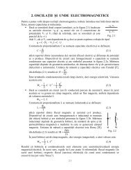
Technical Sciences and Applied Mathematics<br />
REVIEW OF CONTRIBUTIONS REGARDING COANDA EFFECT<br />
Ionică CÎRCIU*, Sorin DINEA**, Mircea BOŞCOIANU*<br />
*“Henri <strong>Coanda</strong>” Air Force Academy, Braşov<br />
**University <strong>of</strong> Bucharest<br />
Abstract: <strong>Coanda</strong> effect is the phenomena in which a jet flow attaches itself to a nearby surface and<br />
remains attached even when the surface curves away from the initial jet direction.In free surroundings, a<br />
jet <strong>of</strong> fluid entrains and mixes with its surroundings as it flows away from a nozzle. When a surface is<br />
brought close to the jet, this restricts the entrainment in that region. As flow accelerates to try balance the<br />
momentum transfer, a pressure difference across the jet results and the jet is deflected closer to the<br />
surface - eventually attaching to it.<br />
Key words: slot, attached jet, static pressure, centrifugation zone, suction zone.<br />
1. INTRODUCTION<br />
The Coandă effect or fluid jet deviations<br />
closed to curl surfaces was observed by Henri<br />
Coandă (1910) during his first flight powered<br />
by jet propulsion (Fig.1).<br />
a) b)<br />
Fig. 1 The geometry <strong>of</strong> <strong>Coanda</strong> jets<br />
In author’s description (<strong>Coanda</strong>, 1969), this<br />
effect is “based on the creation <strong>of</strong> a<br />
depressurized zone in the main air stream<br />
along a wall, which permits flows to get the<br />
wall direction where the pressure difference<br />
was trigged”. In fact this is a transformation <strong>of</strong><br />
a linear jet in a curled jet based on the<br />
attachement at a divergent wall. After lengthy<br />
research, the engineer obtained the French<br />
patent act nr. 792754 <strong>of</strong> October 8, 1934 and<br />
the Romanian one, nr. 24376 <strong>of</strong> October 4,<br />
1935, entitled Procedure and device for the<br />
deviation <strong>of</strong> one fluid into another.<br />
2. THE BASIC ASPECTS OF COANDA<br />
EFFECT<br />
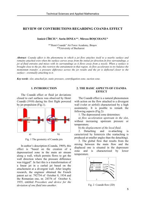
The Coandă effect is a natural phenomenon<br />
with action on the flow attached to a divergent<br />
wall (volet or airfoil) characterized by a high<br />
assimmetry. It is posible to remark the<br />
following aspects (Fig.2):<br />
1. The depressured zone determines:<br />
a) flow acceleration upstream in the slot,<br />
without increasing upstream pressure or<br />
temperature;<br />
b) the displacement <strong>of</strong> the local fluid.<br />
2. Detaching and re-attaching is<br />
caracterized by histerezis (the reattaching is<br />
produced at smaller angles than the detaching).<br />
3. The global flow that results from the<br />
mixing between the main flow and the<br />
displaced one is situated in the depressure<br />
zone and is characterized by lower<br />
temperature. Fig. 2 Coandă flow (2D)<br />
5
6<br />
<strong>Review</strong> <strong>of</strong> <strong>Contributions</strong> <strong>Regarding</strong> <strong>Coanda</strong> <strong>Effect</strong><br />
3. AN ANALYSIS OF THE GEOMETRY<br />
OF COANDA EJECTORS<br />
For a 2D attached jet type flow there<br />
results a first class <strong>of</strong> <strong>Coanda</strong> ejectors with<br />
rectangular section (Fig.3), that could function<br />
also with limitation wall.<br />
Another type <strong>of</strong> ejectors is represented by<br />
the axial symmetric device (external vs.<br />
internal ejectors Fig. 4).<br />
a) b) c)<br />
Fig.3. Rectangular (2D) ejectors: a) 2D <strong>Coanda</strong> flow; b) 2D Ejection device; c) 3D Ejection device<br />
with limiting wall<br />
a) b)<br />
Fig. 4 Ejection device: a) Lenticular external ejection device; b) Lenticular internal ejection device<br />
4. A GLOBAL ANALYSIS OF THE<br />
MIXING PROCESS IN THE EJECTION<br />
DEVICE<br />
Let consider an ejection device that we are<br />
going to analyse from the point <strong>of</strong> view <strong>of</strong> the<br />
mixture between the primary flows, the active<br />
one, through which energy is introduced into<br />
the system, and the secondary flow.<br />
Fig. 5 <strong>Coanda</strong> ejector with non-uniform speed<br />
distribution<br />
Fig. 6 <strong>Coanda</strong> ejector with uniform speed<br />
distribution<br />
In the inlet (Section 0-0), the primary flow<br />
is introduced by compression, acceleration or<br />
through absorbtion directly from the<br />
environment. The absorbtion section (h-h)<br />
through which the resulting inflow moves only<br />
and is characterized by the fact that the total<br />
enthalpy i* <strong>of</strong> the flow is the same with that <strong>of</strong><br />
the environment iH*. The place around A is<br />
supposed to be the spot where the<br />
depressurization flow is maximal. Section B-B
shows the end <strong>of</strong> the <strong>Coanda</strong> pr<strong>of</strong>ile (line<br />
OAB). Section C-C is where the absorption<br />
section ends and the thickness <strong>of</strong> the mixin<br />
region equals that <strong>of</strong> the C-C section. D-D is<br />
the exit section from the ejection disposal and<br />
is characterized through the fact that the static<br />
pressure is equal with that <strong>of</strong> the environment<br />
static pressure pH. The area h-0-C-B-h is<br />
considered to be the absorption area where the<br />
total enthalpy i* <strong>of</strong> the flow is the same as that<br />
<strong>of</strong> the environment iH*. Area 0-ABC-C-0 is<br />
considered to be that <strong>of</strong> the mixture where the<br />
whole quantity <strong>of</strong> generated flow is received<br />
through the permeable surface C0. Area C-D-<br />
D-C is the area <strong>of</strong> acquiring uniformity for<br />
aerothermogazodynamic parameters in section<br />
C-C and it usually has a divergent form, which<br />
contributes to the increase <strong>of</strong> efficiency <strong>of</strong> the<br />
ejection device. Its existence leads to the<br />
increase <strong>of</strong> the generated flow but it does not<br />
necessarily mean an increase <strong>of</strong> the propulsion<br />
force. The research on the force increase will<br />
have to take into consideration the entire<br />
geometry <strong>of</strong> the ejection device. The known<br />
factors are the geometry <strong>of</strong> the ejection device<br />
in its sections (Ah, A0, AB = AC, AD), the<br />
fuel conditions in the slot (p*, P0), and<br />
environmental conditions (p H, ρ H, i H*). Also,<br />
for this global analysis <strong>of</strong> the mixture in the<br />
ejection device the values <strong>of</strong> the energetic<br />
performance ηC, ηD on sections 00-CC, 00-<br />
DD, are considered as known.<br />
In Fig. 7 is presented the distribution <strong>of</strong><br />
speed in a section <strong>of</strong> the <strong>Coanda</strong> ejection<br />
device with two different regions, an<br />
asymmetrical one (d width), and a uniform one<br />
(D-d width) where the length <strong>of</strong> the boundary<br />
layer at the wall being s.<br />
Fig. 7 Distribution <strong>of</strong> speed in a section<br />
Technical Sciences and Applied Mathematics<br />
5. CASE STUDY: COANDA EJECTION<br />
DEVICE WITH UNEVEN SPEED<br />
Let a <strong>Coanda</strong> ejector with non-uniform and<br />
variable speed distribution. In the D exit<br />
section, the static pressure pD equals the<br />
environment pressure pH. The power<br />
transferred to the fluid in D section is:<br />
P0 = ηPD = ∫ H<br />
AD<br />
3<br />
ρHV<br />
MDA<br />
Dχ3D<br />
=<br />
2<br />
ρ VD ( )<br />
* *<br />
y ( i )<br />
i − dAD<br />
D<br />
H<br />
(1)<br />
The gain force is given by the difference<br />
between the two force distributions, with a<br />
maximal value corresponding to A:<br />
Fig. 8 Force distributions on <strong>Coanda</strong> airfoil<br />
Let detail <strong>Coanda</strong> flow by using two zones<br />
with special properties, the centrifugation zone<br />
and the suction zone.<br />
Fig. 9 Detailed analysis <strong>of</strong> Coandă flow<br />
The equations for the centrifugation zone<br />
that is associated to the mixing region 0-ABC-<br />
C-0 with C0 permeable are:<br />
1 ∂(<br />
ρ⋅<br />
u ω )<br />
⋅ = 0<br />
(2)<br />
r ∂ω<br />
u 1 p<br />
r r<br />
7<br />
2<br />
∂<br />
− = −<br />
ρ ∂<br />
ω<br />
(3)
8<br />
∂u 1 ∂p<br />
ω u ω = −<br />
∂ω<br />
ρ ∂ω<br />
i<br />
k−1<br />
<strong>Review</strong> <strong>of</strong> <strong>Contributions</strong> <strong>Regarding</strong> <strong>Coanda</strong> <strong>Effect</strong><br />
(4)<br />
p k<br />
2<br />
* ⎛ ⎞ u<br />
= iH<br />
⎜ +<br />
p ⎟<br />
(5)<br />
⎝ H ⎠ 2<br />
* ω<br />
Fig. 10 Element <strong>of</strong> jet<br />
For a small element <strong>of</strong> jet flow, the radial<br />
movement equation is:<br />
dR dp<br />
= 2<br />
(6)<br />
R ρu<br />
ω<br />
For Bi on the pr<strong>of</strong>ile:<br />
u ω = u ω0f<br />
u ( R)<br />
u ω0<br />
= u0fu0<br />
(7)<br />
and the total enthalpy is conserved:<br />
2<br />
2<br />
* ( )<br />
[ u ω(<br />
R)<br />
] [ u ω(<br />
R)<br />
] *<br />
i R = + dR R + ic<br />
2 ∫<br />
(8)<br />
R<br />
The static pressure is expressed by:<br />
2<br />
k −1<br />
[ u ( R ) ] ⎞<br />
⎛ 1<br />
p ( R)<br />
= p ⎜<br />
ω<br />
H 1<br />
dR ⎟<br />
⎜<br />
+ *<br />
R<br />
i ∫<br />
H R ⎟<br />
(9)<br />
⎝<br />
⎠<br />
and the static density ad static temperature<br />
are:<br />
1<br />
[ ( ) ]<br />
2<br />
⎛ k<br />
1 u R ⎞ −<br />
ω<br />
ρ ( R)<br />
= ρ ⎜ H 1<br />
dR ⎟<br />
⎜<br />
+ *<br />
R<br />
i ∫<br />
H R ⎟<br />
(10)<br />
⎝<br />
⎠<br />
T<br />
( R)<br />
2 k−1<br />
[ u ( R)<br />
] ⎞<br />
⎛ 1<br />
= T ⎜ H⎜<br />
1+<br />
*<br />
i ∫<br />
⎝ H<br />
ω<br />
R<br />
dR ⎟ R ⎟<br />
⎠<br />
(11)<br />
The gain in force at Bi:<br />
k<br />
k<br />
k<br />
φ Bi =<br />
1<br />
b<br />
f<br />
0<br />
f<br />
⎜<br />
⎝ i<br />
( R)dR<br />
[ u ( R)<br />
]<br />
2<br />
⎛ 1<br />
⎞k−1<br />
ω<br />
∫ ⎜1+<br />
dR<br />
* ∫<br />
⎟ R<br />
R1<br />
H R ⎟<br />
⎠ (12)<br />
R2<br />
2 2<br />
u0<br />
u<br />
and the corresponding efficiency is:<br />
η Bi<br />
=<br />
1<br />
b<br />
f<br />
0<br />
f<br />
⎜<br />
⎝ i<br />
( R)dR<br />
[ u ( R)<br />
]<br />
2<br />
⎛ 1<br />
⎞k<br />
−1<br />
ω<br />
∫ ⎜1+<br />
dR<br />
* ∫<br />
⎟ R<br />
R1<br />
H R ⎟<br />
⎠<br />
(13)<br />
R2<br />
3 3<br />
u0<br />
u<br />
We note that the flow attached is situated<br />
in the depressure zone defined by the exit from<br />
slot, 0-0, B-B section and D-D exit with a<br />
maximal value in A.<br />
6. CONCLUSIONS<br />
In the conclusion we can state that for the<br />
same energy available P0, the D f force gain<br />
can be obtained by decreasing the speed<br />
VD < VM, similarly to an increase by ejection<br />
<strong>of</strong> the mass flow evacuated.<br />
In order to obtain the highest force possible<br />
for an available used energy it is preferable to<br />
put into motion the highest amount <strong>of</strong> fluid<br />
possible with the lowest speed possible instead<br />
<strong>of</strong> a small amount <strong>of</strong> fluid put into motion<br />
with a high speed.<br />
REFERENCES<br />
1. Berbente, C., Constantinescu, N.V,<br />
Dinamica gazelor şi Dinamica fluidelor<br />
vâscoase, Aerotermochimie, UPB,<br />
Bucuresti, 1985;<br />
2. Carafolie, E., Constantinescu, N.V.,<br />
Dinamica fluidelor compresibile, Ed.<br />
Academiei RSR, Bucuresti, 1984;<br />
3. Coandă, H., Air - source du progress,<br />
Book - [s.l.], qqq, aprox. 1961;<br />
4. Coandă, H., Fluid propulsion system<br />
Patent US3337121, 1967;<br />
5. Coandă, H., Programme d'etude et de<br />
realisation d'un aerodyne actionne par un<br />
systeme thermosouflant, 1960;<br />
6. Constantinescu, N.V., Galetuse, S.,<br />
Mecanica fluidelor şi elemente de<br />
aerodinamică, Ed. didactică şi pedagogică,<br />
Bucureşti, 1983.<br />
k<br />
k