System Engineering Simulation Applied to Motorsport - Ricardo
System Engineering Simulation Applied to Motorsport - Ricardo
System Engineering Simulation Applied to Motorsport - Ricardo

Create successful ePaper yourself
Turn your PDF publications into a flip-book with our unique Google optimized e-Paper software.
<strong>System</strong> <strong>Engineering</strong> <strong>Simulation</strong><br />
<strong>Applied</strong> <strong>to</strong> Mo<strong>to</strong>rsport<br />
Fred Jacquelin<br />
Fred.Jacquelin@<strong>Ricardo</strong>.com<br />
Richard Broda<br />
Richard.Broda@<strong>Ricardo</strong>.com
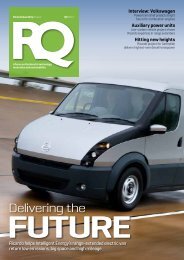
SYSTEM ENGINEERING VISION<br />
The future of vehicle engineering lies in virtual evaluation and development of complete vehicle systems<br />
through high fidelity component and subsystem models operating in a co-simulation environment, enabling<br />
hardware-in<br />
in-loop component evaluation & development linked <strong>to</strong> a highly responsive vehicle simula<strong>to</strong>r that<br />
delivers human-in<br />
in-loop interaction and evaluation<br />
SIMULATION<br />
REAL TIME<br />
HiL<br />
OPTIMIZATION<br />
CONTROL<br />
This allows for the optimization of each component within the operating range of the system it is part of.<br />
The main advantages are:<br />
Allows for a complete trade-off analysis between each components performance<br />
Achieves an overall optimum for the system<br />
Allows for the testing and evaluation of each component before it is built<br />
Reduces the development cycle by using high fidelity simulation codes with fast run time and optimization<br />
Reduces the number of mule vehicles <strong>to</strong> be built and tested<br />
Using a simula<strong>to</strong>r as early as the concept stage will provide a safe evaluation environment
SYSTEM ENGINEERING SIMULATION<br />
<strong>Ricardo</strong> is championing the development of new methods and co-simulation strategies <strong>to</strong> achieve the<br />
optimization of increasingly complex system driven by new requirements [fuel economy, performance, emissions,<br />
etc…]<br />
The transient behavior of an au<strong>to</strong>motive system becomes very important in achieving these targets as simulation:<br />
Allows for a realistic assessment of component performance during real life operation<br />
Allows the development team <strong>to</strong> focus on the challenges early on and re-direct the program as necessary<br />
hence saving time and money<br />
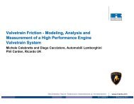
Example: WAVE - MATLAB - EASY5 co-simulation<br />
In the development of a sequential turbo-charged LDD engine,<br />
MATLAB Simulink + WAVE was used <strong>to</strong> size the boosting system and<br />
develop control maps at steady state.<br />
Steady State Modeling<br />
Fueling mg/inj<br />
Transient Modeling<br />
Fueling Map<br />
The Simulink + WAVE model was then linked <strong>to</strong> a vehicle model in<br />
EASY5 for transient performance simulation. Only then can the impact<br />
of the design decision pertaining <strong>to</strong> the location of the 2 turbochargers<br />
be achieved.<br />
Shorter pipe<br />
Rack Position<br />
Wastegate Area<br />
Valve Position<br />
Valve Position<br />
Engine Model<br />
HP VGT Position<br />
LP Turbine Wastegate Area<br />
HP Turbine Bypass Valve Position<br />
HP Compressor Bypass Valve Position<br />
Torque<br />
RPM<br />
Throttle Command<br />
EASY5 Vehicle<br />
Model<br />
Vehicle<br />
Speed<br />
Tire<br />
Slip<br />
Throttle<br />
Command<br />
+ RPM<br />
EASY5 Driver<br />
Model<br />
Speed<br />
Setpoint<br />
Normalized Boost Pressure Trace during Transient Acceleration
MOTORSPORT APPLICATION CONCEPT: LAPTIME<br />
Performance Response<br />
Trajec<strong>to</strong>ry<br />
design parameters<br />
Steering Controller<br />
Optimizer<br />
Braking Controller<br />
Speed targets design<br />
parameters<br />
Throttle Controller<br />
Engine design<br />
parameters<br />
Engine Calibration<br />
This provides for the overall<br />
optimization solution for a specific track<br />
and vehicle set up without the need for<br />
a complex driver model.<br />
Only the physical properties of the<br />
vehicle system matter in finding an<br />
optimum solution.<br />
Drive-Line<br />
design parameters<br />
Chassis/vehicle<br />
design parameters<br />
Powertrain Calibration<br />
Vehicle Calibration<br />
SIMULATION<br />
WAVE -RT<br />
VSIM<br />
The optimizer behaves similarly <strong>to</strong> a<br />
driver or crew chief. It finds the best<br />
trajec<strong>to</strong>ry line, throttle and braking<br />
points. To optimize a large amount of<br />
sub-system, parallel processing is<br />
required.
MOTORSPORT APPLICATION: TOOLS<br />
WAVE-RT BETA provides realistic<br />
transient engine response and allows<br />
for various technologies <strong>to</strong> be tested<br />
on the fly. Real Time capable when<br />
compiled.<br />
WAVE-RT<br />
RT BETA<br />
inputs<br />
CarSim S Function<br />
Chassis model<br />
Vehicle characteristics<br />
Tire models<br />
Race track data<br />
outputs<br />
RT-Engine<br />
WAVE<br />
--- RT Engine Model<br />
--- WAVE<br />
Physical model<br />
Intake/exhaust<br />
dynamics<br />
Real-Time capable<br />
Data Analysis<br />
Graphs<br />
Throttle / Brake<br />
Controller<br />
--- RT Engine Model<br />
--- Steady State Map<br />
VSIM Powertrain Model<br />
Transmission mode<br />
Up/Down Shift Points
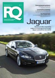
MOTORSPORT APPLICATION: OPTIMIZATION 1<br />
Example 1: Constant Speed – S shape turn<br />
Genetic Algorithm is used <strong>to</strong> optimize the section time on an S-shaped<br />
turn divided in<strong>to</strong> 2 sections. 7 stations with variable longitudinal location<br />
on the track were set. For each station, a variable lateral target from the<br />
road centerline is used <strong>to</strong> generate a target trajec<strong>to</strong>ry input <strong>to</strong> the<br />
steering controller. Speed is maximized over the track.<br />
Section Time Minimization<br />
The optimizer finds an optimum solution with the constraint being that<br />
the conditions at the end of turn 1 are identical <strong>to</strong> turn 2 starting<br />
conditions.<br />
Station n+1<br />
Trajec<strong>to</strong>ry<br />
target<br />
Station n<br />
Design Parameters:<br />
-Vehicle speed<br />
- 7 stations positions<br />
- Trajec<strong>to</strong>ry targets @ 7 stations<br />
Output:<br />
Turn 1 and 2 run time<br />
Feasible Vehicle Speed<br />
Red car: feasible run<br />
Blue Car: Unfeasible<br />
Black Car: Optimized<br />
ANIMATION<br />
Run Time: 1h [with steady state <strong>to</strong>rque curve]
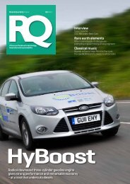
MOTORSPORT APPLICATION: OPTIMIZATION 2<br />
Example 2: Full Optimization – Simple Track<br />
In this example, DoE and optimization are used <strong>to</strong> optimize vehicle<br />
speed and trajec<strong>to</strong>ry as well as powertrain design parameters, in this<br />
case related <strong>to</strong> engine performance using WAVE-RT.<br />
The Data Mining Tool is used <strong>to</strong> choose a baseline vehicle set up with<br />
good overall performance from the DoE runs. The optimization method<br />
is a mix of explora<strong>to</strong>ry and gradient base method in order <strong>to</strong> avoid a<br />
local minimum.<br />
Legend:<br />
Best DoE<br />
[turn2]<br />
OPTIMZED<br />
Best DoE<br />
[turn1]<br />
Lap Time [s]<br />
33.0<br />
32.0<br />
31.0<br />
30.0<br />
29.0<br />
28.0<br />
27.0<br />
26.0<br />
25.0<br />
GRADIENT<br />
BASE<br />
Lap Time Optimization<br />
HOW TO AVOID?<br />
LOCAL OPTIMUM<br />
Data<br />
Mining<br />
EXPLORATORY PHASE<br />
0 100 200 300 400 500 600<br />
Run Counter<br />
Run Time: 15h [with engine model not compiled]<br />
• 30 trajec<strong>to</strong>ry and speed target parameters<br />
• Intake and Exhaust cam timing<br />
Optimized vehicle data is passed <strong>to</strong><br />
CFD for dry sump oil motion during<br />
turn 2 operation
G-G Diagram Based Optimization – new development<br />
Example 3: Full Track<br />
The track is divided in<strong>to</strong> 9 sections and a piece-wise optimization is<br />
performed so as <strong>to</strong> match the end/start conditions of each segment.<br />
This is achieved by overlapping each segment during the optimization.<br />
Waterford Hills Track<br />
Optimized trajec<strong>to</strong>ry<br />
The optimization is performed using the vehicle maximum longitudinal<br />
and lateral acceleration capability. This can be achieved by running<br />
various maneuvers simulation with CarSim. It was approximated in this<br />
example. The vehicle trajec<strong>to</strong>ry is parameterized as in the previous<br />
examples and a MATLAB code computes the critical vehicle velocity at<br />
each apex [max. lateral acceleration] and fills in between based on the<br />
vehicle longitudinal acceleration capabilities for each trajec<strong>to</strong>ry iteration.<br />
The results can be used as the baseline start point for the optimization<br />
using the full co-simulation <strong>to</strong>ol and hence shorten run time. It can also<br />
be used for assessing the track characteristics and make quick decision<br />
on the vehicle set up.<br />
-- 1 st iteration<br />
-- 2 nd iteration<br />
-- 3 rd iteration<br />
Waterford Hills Track<br />
Optimized Velocity Profile
Future Development<br />
The laptime simulation <strong>to</strong>ol was developed by <strong>Ricardo</strong> <strong>to</strong> demonstrate the maturity of the available codes and<br />
the possible connection between them. Analysis led design will become a standard in the industry in order <strong>to</strong><br />
reach future vehicle requirements.<br />
The Virtual Vehicle <strong>System</strong> goals are <strong>to</strong> provide:<br />
Vehicle <strong>Simulation</strong><br />
WAVE-<br />
RT, VSIM<br />
HiL<br />
Compiled Code<br />
Running in Real-Time<br />
Controller<br />
Emulation<br />
Outputs<br />
High-fidelity replication of vehicle performance and feel<br />
Reduced iterations of pro<strong>to</strong>type hardware<br />
Reduced development time when hardware changes are virtual<br />
Reduced dependence on test tracks and environmental trips<br />
Improved test repeatability<br />
Vehicle equipped with an extensive array of virtual instrumentation<br />
(simulation state variables) which can be used in objective rating<br />
systems<br />
Simplified calibration or algorithm comparison<br />
Ability <strong>to</strong> do “what-if” testing and comparison when hardware does<br />
not exist<br />
Driver Control<br />
Inputs<br />
WAVE-RT BETA and CarSim were run successfully real time on a 2<br />
processor OPAL-RT system. For future simula<strong>to</strong>r work, CarSim will<br />
handle the connectivity with the hardware and driver with WAVE-RT<br />
and VSIM replacing the CarSim engine and transmission blocks.<br />
Vehicle Simula<strong>to</strong>rs
Conclusion<br />
The lap time <strong>to</strong>ol provides a platform <strong>to</strong> implement new methods in system engineering:<br />
Integrates specialized codes in<strong>to</strong> one robust environment that best fit the application<br />
Integrate in-house codes without sharing Intellectual Properties [use of ISIS]<br />
Access a large amount of interacting design variables <strong>to</strong> scan the full system design space<br />
Use advanced DoE, optimization and cus<strong>to</strong>mized methods <strong>to</strong> optimize the full system and avoid:<br />
‣ local optimums<br />
‣ lengthy simulation time<br />
Use network resources in order <strong>to</strong> minimize run time [parallel processing, ISIS]<br />
Be accessible from remote locations [ISIS]<br />
Au<strong>to</strong>matically share outputs <strong>to</strong> different engineering departments for secondary studies [CFD, FEA, etc…w/ ISIS]<br />
In its actual set-up each software can be used for Real-Time simulation. This is a key asset as HiL and Man-in-the-Loop development<br />
activities are increasingly a major part of au<strong>to</strong>motive development programs. The methodology used by the laptime simulation <strong>to</strong>ol is<br />
applicable and being implemented in many au<strong>to</strong>motive system development such as:<br />
Conventional vehicle development including after-treatment simulation<br />
Hybrid vehicle systems<br />
Advanced concepts [camless engines integration, 2 stroke/4 stroke switching “HULK” engine, etc…]<br />
Contact information:<br />
Peter Brown, Vice President, Propulsion <strong>System</strong>s Peter.Brown@<strong>Ricardo</strong>.com 734-394-3750<br />
Russell J. Wakeman, Technical Direc<strong>to</strong>r Russ.Wakeman@<strong>Ricardo</strong>.com 734-394-3794<br />
Fred Jacquelin, Group Leader, Engine & Vehicle <strong>Simulation</strong> Fred.Jacquelin@<strong>Ricardo</strong>.com 734-394-3923<br />
The authors would like <strong>to</strong> thank:<br />
Charles Paulson, Ben Ferguson at <strong>Ricardo</strong>, Inc.<br />
Dave Hall, Phil Mather and all the team at Mechanical <strong>Simulation</strong><br />
Charles Yuan, Malik Kayupov, Mike Sheh at Engineous Software<br />
Wensi Jin, OPAL-RT