Q2 2009 - Ricardo
Q2 2009 - Ricardo
Q2 2009 - Ricardo

You also want an ePaper? Increase the reach of your titles
YUMPU automatically turns print PDFs into web optimized ePapers that Google loves.
Software&CAE<br />
The powertrain design software and CAE newsletter of <strong>Ricardo</strong><br />
<strong>Q2</strong> <strong>2009</strong><br />
PISDYN helps Mahle Metal<br />
Leve avoid liner cavitation<br />
Cavitation of heavy duty diesel<br />
cylinder liners is a major and longidentified<br />
problem, yet the underlying<br />
mechanisms causing it remain<br />
little understood. Using PISDYN to<br />
analyse an engine affected by this<br />
issue, Mahle Metal Leve SA of<br />
Brazil has identified both the cause<br />
and a cost-effective solution.<br />
Premature corrosion of the replaceable cast-iron<br />
cylinder liners in heavy duty diesel engines is a<br />
major reliability and durability issue for designers.<br />
This corrosion is typically caused by cavitation<br />
from high frequency pressure changes at the<br />
interface between the metal surface of the liner<br />
and the coolant. In 2008 Dr Estela Bueno of<br />
Mahle Metal Leve S.A. and Luis Raminelli of<br />
MWM International Motores undertook a major<br />
research programme to better understand the<br />
causes of and possible solutions to the problem<br />
using <strong>Ricardo</strong>’s PISDYN software.<br />
The issue became apparent during tests with a<br />
heavy duty diesel engine which began showing<br />
significant cylinder liner cavitation problems.<br />
The engine had a cast iron block with chrome<br />
plated steel liners and aluminium alloy pistons.<br />
Despite having the same cylinder pressures<br />
and similar cylinder block, piston, liner and<br />
gudgeon pin design, the power output of the<br />
new engine was much higher; this led the<br />
researchers to believe that the increased load<br />
might be a factor in causing cavitation.<br />
When coolant is near its boiling point, vapour<br />
bubbles form and then collapse against the<br />
vibrating metal surface on the coolant side<br />
of the liner, eroding its steel surface. Several<br />
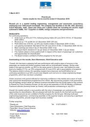
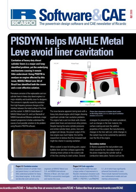
Piston-liner clearances at bottom dead centre<br />
on the firing stroke (above); close-up of cavitation<br />
erosion (below/left).<br />
strategies for preventing this were considered,<br />
such as changes in the liner material, the<br />
surface coating and even the additive<br />
properties of the coolant. But manufacturing<br />
changes to the liner add cost, while changes to<br />
the coolant may not be sustained by operators<br />
over the life of the engine.<br />
Secondary motion<br />
Dr Bueno suspected the real problem was<br />
shock caused by the ‘secondary motion’ of<br />
the piston impacting the cylinder wall as<br />
combustion takes place. Factors such as the<br />
In this Issue<br />
Pages 1-3 Cavitation erosion<br />
Cavitation erosion of cylinder liners<br />
and parent bores is a well known if<br />
little understood problem for heavy<br />
duty diesel engines. In this article<br />
we describe work carried out by<br />
engineers at Mahle Metal Leve<br />
S.A. and MWM International<br />
Motores of Brazil, who have used<br />
PISDYN to successfully investigate<br />
and resolve this issue.<br />
Pages 3-4 Code upgrades<br />
The past twelve months has seen<br />
a large number of improvements to<br />
<strong>Ricardo</strong>’s mechanical simulation suite<br />
with the introduction of VALDYN 4.3,<br />
SABR 2.1, PISDYN 5.1 and RINGPAK<br />
5.1, all of which have significantly<br />
enhanced functionality to users.<br />
These include improved functionality,<br />
new mathematical models and user<br />
interface enhancements.<br />
.ricardo.com/SCAE • Subscribe free at www.ricardo.com/SCAE • Subscribe free at www.ricardo.com/SCAE
PISDYN helps Mahle Metal Leve avoid liner cavitation<br />
gudgeon pin offset and piston profile are known<br />
to have a potentially significant influence on<br />
liner cavitation. It was decided to investigate<br />
three different potential solutions to the<br />
problem. The first was to change the viscosity<br />
of the coolant by the use of additives to inhibit<br />
the formation of the vapour bubbles. The second<br />
was to change the liner material to a harder<br />
steel with a nitrate surface treatment, and the<br />
third was to investigate the effect of vibration<br />
introduced to the liner by the secondary motion<br />
of the piston.<br />
Neither the change in liner material nor the<br />
coolant additives made any difference, and<br />
the issue persisted. As a result, the focus<br />
of investigation was turned to the source<br />
of vibration responsible for the formation of<br />
bubbles in the coolant. This was done by making<br />
a detailed analysis of the piston’s behaviour<br />
in relation to the cylinder liner, using <strong>Ricardo</strong>’s<br />
PISDYN software.<br />
The investigation was divided into three parts.<br />
The first phase was to create a baseline model<br />
capable of representing the piston secondary<br />
motion instability during the thermal shock test<br />
at the engine’s rated power output, something<br />
which proved very effective in revealing<br />
cavitation. The engine was run at rated power<br />
with high temperature and load, then low<br />
temperature coolant was suddenly introduced<br />
into the engine with power maintained. The<br />
cycle was repeated for 100 hours in a test aimed<br />
at exposing the liner to aggressive conditions<br />
likely to accelerate the cavitation process. The<br />
second phase was to optimise the offset of<br />
the piston pin and the third sought to perform<br />
a vertical profile optimisation of the piston in<br />
order to achieve the best piston secondary<br />
motion behaviour.<br />
In creating the baseline model and to ensure the<br />
success of the simulation, several key factors<br />
were considered. These were the cylinder<br />
pressure diagram, the shape of the liner when<br />
the engine was running, and any thermal<br />
deformation of the piston. Cylinder pressures<br />
were measured during the physical engine<br />
testing at rated power for use in the simulation<br />
work. The liner shape was evaluated using finite<br />
element analysis, taking into account thermal<br />
expansion using temperature data harvested<br />
during physical testing. Other factors considered<br />
included the piston profile, thermal expansion<br />
and compliance.<br />
Simulation using PISDYN revealed a significant<br />
rate of change of lateral forces in the piston<br />
as well as substantial, though not unusual,<br />
deformation of the piston skirt. These results<br />
suggested considerable excitation of the<br />
cylinder liner but in order to quantify the extent<br />
of the condition, the analysis was made on the<br />
earlier, less powerful, cavitation-free engine for<br />
comparison. This engine produced 20 per cent<br />
less power and lateral forces in the piston were<br />
30 per cent less – despite cylinder pressures on<br />
a par with the more powerful engine.<br />
Piston impacts cause liner excitation<br />
These results strongly indicated that high<br />
excitation of the liner was being caused by the<br />
piston striking the cylinder surface. At the same<br />
time, it was also important to evaluate both the<br />
magnitude and the rate of change of this lateral<br />
force as well as any tendency to deform the<br />
components involved.<br />
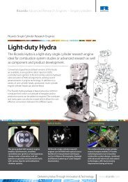
Distorted hot shape of liner at rated power (left).<br />
The next phase was to solve the problem by<br />
optimising the gudgeon pin offset, something<br />
which has a marked effect on piston secondary<br />
motion. In standard form, the pin sat on the<br />
centreline of the piston with no offset at all.<br />
PISDYN was used to analyse the effects of<br />
moving the gudgeon pin towards both the thrust<br />
and non-thrust side of the piston in steps of<br />
0.25mm. The piston lateral stability was found<br />
to be at its worst between 0mm and 0.5mm on<br />
the non-thrust side.<br />
Moving it to the thrust side reduced the<br />
cavitation but created unwanted secondary<br />
effects due to lateral loads and the rocking<br />
angle. At bottom dead centre, for example,<br />
there was a high rate of change of secondary<br />
kinetic energy. This was not expected to<br />
cause cavitation because the energy levels<br />
were lower, but it was likely to increase wear<br />
to unacceptable levels. With the pin moved<br />
towards the non-thrust side, these conditions<br />
were improved but lateral loads increased,<br />
especially at the largest offset of 1.5mm.<br />
Combined with a baseline liner material (steel<br />
with a chromo coating) and using pure water<br />
as the coolant, testing focused on a pin offset<br />
to either the thrust or non-thrust side of 1.0mm<br />
and a 0.75mm offset to the non-thrust side.<br />
After testing, the piston with the 1.0mm thrust<br />
side offset suffered heavy marking to the middle<br />
of the skirt and the second land. Similarly, the<br />
piston with the offset to the non-thrust side<br />
showed heavy marking to the skirt thrust side.<br />
However, the offset of 0.75mm resulted in no<br />
marking and also solved the cavitation problem.<br />
Sensitivity to offset<br />
Through simulation using PISDYN, it soon<br />
became apparent that secondary motion of<br />
the piston is very sensitive to the gudgeon pin<br />
2 <strong>Ricardo</strong> Software & CAE • <strong>Q2</strong> <strong>2009</strong>
Mechanical simulation upgrades marked with four important releases<br />
offset and a simple and economical solution<br />
was found to a serious problem. The process<br />
also highlighted the potential for optimising<br />
the design of the piston profile for improved<br />
dynamic performance and stability in secondary<br />
motion, where both skirt and land profiles play<br />
a major role.<br />
One other important factor is that any dynamic<br />
simulation of piston behaviour must account<br />
for several different variables simultaneously.<br />
Piston secondary motion depends on factors<br />
including the piston mass centre position,<br />
gudgeon pin offset, gas pressure centres, and<br />
the shape of the liner at high temperatures.<br />
The investigation also explains why some<br />
engine designs with the piston mass aligned<br />
with the pin centre (usually considered to be<br />
unfavourable for dynamic reasons) produce<br />
lower cavitation effects than those in which<br />
the centre of piston mass and pin centrelines<br />
are offset.<br />
Though the analysis proved to be a complete<br />
success, it is not possible to establish a<br />
default value applicable to all engines because<br />
cavitation depends on such a large number of<br />
factors, and includes cooling liquid composition<br />
and flow behaviour, liner material and surface<br />
finish. However, the project demonstrated how<br />
powerful PISDYN can be when the results are<br />
quantified and validated using analysis of a<br />
similar engine where no cavitation occurs.<br />
Mechanical simulation upgrades<br />
marked with four important releases<br />
The last 12 months has seen a host of improvements<br />
to <strong>Ricardo</strong>’s mechanical suite with the introduction of<br />
VALDYN 4.3, SABR 2.1, PISDYN 5.1 and RINGPAK 5.1,<br />
all of which have significantly enhanced functionality<br />
to users. VALDYN is <strong>Ricardo</strong>’s multi-body dynamic<br />
and kinematic simulation package which has been<br />
specifically developed for valvetrain and drive system<br />
analysis and cam and spring design. VALDYN 4.3<br />
was released in the summer of 2008 and includes the<br />
major enhancement of run distribution, which makes<br />
this powerful application accessible to many more<br />
customers than before.<br />
With VALDYN, it is now possible to use multiple<br />
CPUs on a network to run a single model with<br />
multiple cases or perform parametric studies with<br />
varying parameters in one session. Put simply,<br />
this involves spreading the analysis over many<br />
CPUs across a network. Previously, however, this<br />
kind of operation was effectively limited only<br />
to large OEMs because of cost and resources.<br />
In version 4.3, instead of being implemented<br />
for an infinite number of CPUs, a customer can<br />
order VALDYN with a run<br />
distribution licence for 16,<br />
8 or 4 runs per job, greatly<br />
reducing cost. Thanks to<br />
the new licenses, the full<br />
potential of VALDYN has<br />
become accessible to smaller<br />
companies during the last<br />
nine months, with distribution<br />
from a local machine making<br />
it easy to manage the whole<br />
process.<br />
In the spring of <strong>2009</strong>,<br />
PISDYN, <strong>Ricardo</strong>’s advanced<br />
simulation package for<br />
predicting the dynamics<br />
of the piston and connecting rod assembly,<br />
has undergone significant enhancement with<br />
the release of version 5.1. PISDYN primarily<br />
considers the secondary motion of the piston<br />
and the interactions between the skirt, liner and<br />
oil film. In this version, the Reynolds equation<br />
solver options have been removed and replaced<br />
with the faster and more robust method of finite<br />
volume discretization. There are now three<br />
options for the applied boundary conditions<br />
for the Reynolds equation: (1) Reynolds &<br />
Jakobsson-Floberg-Olsson boundary conditions<br />
using the Elrod algorithm; (2) Someya boundary<br />
conditions and algorithm, and; (3) the Half-<br />
Sommerfield boundary condition.<br />
The third option allows the simulation to run more<br />
quickly than it would in option 1 with the proviso<br />
that the solution is not mass conserving. Option 3 is<br />
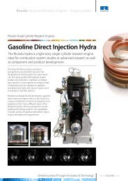
Lubricating oil temperature predictions in PISDYN<br />
(above); VALDYN drive system animation (left).<br />
<strong>Q2</strong> <strong>2009</strong> • <strong>Ricardo</strong> Software & CAE 3
Mechanical simulation upgrades marked with four important releases<br />
equivalent to the v3.3 solver or to selecting the finite<br />
difference method in PISDYN 5.0.<br />
PISDYN’s sister programme, RINGPAK, has<br />
also undergone an upgrade to version 5.1 and<br />
there are some significant improvements. Three<br />
main models are used in RINGPAK for simulating<br />
the lubrication between ring and liner, gas flow<br />
characteristics between the ring, liner and groove<br />
and the dynamics of the ring within the groove.<br />
RINGPAK 5.1 now handles oil flows in the<br />
crown land and groove surfaces. The physical<br />
phenomenon captured by oil transport models is<br />
extremely complex: oil flow is driven by piston<br />
acceleration and surrounding gas flow; oil<br />
thickness on each land and groove is impacted<br />
by the groove/land oil mass balance, and crown<br />
oil transport is a function of ring/liner transport.<br />
RINGPAK 5.1 captures this phenomenon,<br />
and offers further accuracy gains if users can<br />
supply oil film thickness boundary conditions.<br />
In this mode RINGPAK users can run very fast<br />
parametric studies.<br />
In previous versions, the oil entrainment model<br />
was based mainly on blow-back and the<br />
geometry of the top land. Although effective,<br />
there were limitations when it came to<br />
entrained oil sources and droplet distributions.<br />
This model has also been enhanced significantly<br />
so that flow between the crown, rings, and<br />
liner are now considered in detail and the<br />
entrainment oil flows are included in the<br />
oil mass balance. The prediction of oil film<br />
thickness in the crown grooves enables accurate<br />
prediction of the passage of oil droplets into gas<br />
flowing around the piston. By calculating the<br />
system of oil droplet masses over each crown<br />
groove and land, it is possible to accurately<br />
trace the path of oil droplets in the flowing gas<br />
and predict the oil entrainment into both the<br />
cylinder and the crankcase.<br />
The combination of these improvements brings<br />
RINGPAK to a new level of sophistication. In<br />
the past, though good at simulating blow-by<br />
and blow-back, modelling oil consumption was<br />
more difficult. RINGPAK 5.1 not only makes that<br />
SABR, <strong>Ricardo</strong><br />
Software’s shaft,<br />
gear and bearing<br />
concept and design<br />
package<br />
possible but allows accurate simulation of how<br />
oil interacts and passes through the physical<br />
ring pack.<br />
A further major enhancement of RINGPAK, also<br />
catered for in PISDYN 5.1, is the capability to<br />
model ring and skirt scuffing using high fidelity<br />
techniques to capture thermal behaviour.<br />
Scuffing is triggered when total contact<br />
temperature reaches a critical level, with<br />
bulk temperature of the components and the<br />
instantaneous increase in temperature of the<br />
surface, known as flash temperature, also<br />
playing major roles. RINGPAK and PISDYN<br />
can now calculate the heat generated and the<br />
temperature of the ring or skirt respectively,<br />
where it makes contact with the liner. At each<br />
integration step, the heat transfer is solved<br />
for the system that includes ring/skirt, oil and<br />
liner. Predicting flash temperature provides an<br />
indication of when scuffing will occur.<br />
New faster version of SABR<br />
SABR, <strong>Ricardo</strong> Software’s shaft, gear and bearing<br />
concept and design package was also upgraded<br />
to version 2.1 in the last few months. Of major<br />
interest is that solver performance has been<br />
increased by a factor of between 10 and 50,<br />
depending on the job. It also embraces multi-core<br />
solving so when run on any PC with more than<br />
one core (which most modern PCs have) the<br />
speed is increased to between 20 and 100 times.<br />
Previous releases of SABR based bearing life<br />
prediction on the ISO 281 1990 standards;<br />
this has some limitations, particularly<br />
where shaft deflections cause significant<br />
bearing misalignment. SABR 2.1 is based on<br />
ISO/TS 16281, which specifically allows for<br />
misalignment and internal clearance in the<br />
bearings, a feature enabled in the new revision.<br />
SABR 2.1 is also able to show the distribution of<br />
load and stress within a bearing caused by the<br />
gearbox operating loads. This allows the user<br />
to investigate in detail the causes of bearing<br />
damage and the impact of changes in load and<br />
misalignment. The roller bearing model in SABR<br />
has been enhanced to use Hertzian contact<br />
analysis in order to calculate bearing stiffness.<br />
Thanks to enhancements to the Shaft Load<br />
3D view, it is now easier to identify loads and<br />
reactions by clicking on an arrow, highlighting<br />
load values in a table. As part of the analysis<br />
of gear mesh misalignment, SABR also now<br />
displays the line-of-action misalignment as well<br />
as skew and scope. This is more directly related<br />
to counter measures which may be employed,<br />
such as micro-geometry corrections.<br />
Users engaged in reverse engineering of gear<br />
components and working from measured gear<br />
geometry will find that the extra metrology<br />
information for doing this can now be accessed<br />
from the top level of the GUI via the main<br />
geometry tab. 'Specific Slide Ratio' has also<br />
been added to the Gear Geometry Tab making<br />
it easier to design gears while avoiding scuffing<br />
and scoring issues.<br />
For further information about <strong>Ricardo</strong><br />
Software products, support services and<br />
CAE applications please contact:<br />
CAE applications (Europe): Mark.Gregory@ricardo.com<br />
CAE applications (US): Steve.Strepek@ricardo.com<br />
Software Sales:<br />
RS_Sales@ricardo.com<br />
Software Support: RS_Support@ricardo.com<br />
Or visit<br />
www.ricardo.com<br />
Subscribe free at www.ricardo.com/SCAE • Subscribe free at www.ricardo.com/SCAE • Subscribe free at www