CASE STUDY USING PISDYN OF THE EFFECT ON ... - Ricardo
CASE STUDY USING PISDYN OF THE EFFECT ON ... - Ricardo
CASE STUDY USING PISDYN OF THE EFFECT ON ... - Ricardo

You also want an ePaper? Increase the reach of your titles
YUMPU automatically turns print PDFs into web optimized ePapers that Google loves.
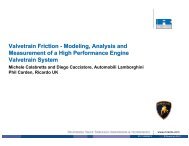
<strong>CASE</strong> <strong>STUDY</strong> <strong>USING</strong> <strong>PISDYN</strong> <strong>OF</strong> <strong>THE</strong> <strong>EFFECT</strong> <strong>ON</strong><br />
PIST<strong>ON</strong> PERFORMANCE <strong>OF</strong> <strong>USING</strong> A L<strong>ON</strong>GER<br />
C<strong>ON</strong>ROD<br />
By: Prabakaran Naganathan and Adrian Martin, ACL Piston Products,<br />
Australia.<br />
ABSTRACT<br />
<strong>PISDYN</strong> simulation software is used by ACL Piston Products to optimise in the design of<br />
pistons, skirt profile, skirt contour, pin-offset and in some cases land diameters. The most<br />
suitable combination of these parameters is required to meet design requirements including<br />
quietness, wear resistance, low friction and durability. <strong>PISDYN</strong> was used to successfully design<br />
a skirt profile and contour for a piston to be used in four-cylinder, petrol engines to be produced<br />
by a major car manufacturer. When the manufacturer wanted a feasibility study of the possibility,<br />
in terms of piston performance, of using a longer connecting rod, this was easily achieved by<br />
merely varying a few parameters in the input deck of the simulations for the original engine. The<br />
study showed that increasing the connecting rod length in this case would not adversely affect<br />
piston performance, apart from causing a small possibility of a “rattle” noise problem.<br />
1 of 13
INTRODUCTI<strong>ON</strong><br />
A key asset of any simulation software is its ability to be easily used for parametric studies and<br />
optimisation. At ACL Piston Products in Australia, <strong>Ricardo</strong>’s <strong>PISDYN</strong> software is used to help<br />
design pistons. The key criteria used to evaluate piston skirt designs performed using <strong>PISDYN</strong><br />
are noise, wear, friction and fatigue strength. It is known that small variations in pin offset, skirt<br />
profile (the small variations in diameter of the skirt with height along the skirt) and skirt contour<br />
(the ovality in the skirt) can have a big influence on how well a piston performs on each of these<br />
criteria. <strong>PISDYN</strong> can be used to determine the most suitable combination of pin offset, skirt<br />
profile, skirt contour and in some cases land diameters for a particular piston application.<br />
Piston noise is caused by the slapping of the piston against the cylinder. This occurs as a result of<br />
the changing interplay of forces on the piston - due to cylinder pressure, inertia and the<br />
supporting force of the connecting rod - as it moves up and down the bore during a cycle. This<br />
noise is greatest when the piston is cold, as this leads to a larger clearance between the skirt and<br />
cylinder, allowing for greater kinetic energy, from lateral and rotational motion to be gathered by<br />
the piston before it impacts the cylinder. Piston noise tends to also be largest during engine start<br />
up when the oil film between the skirt and cylinder may be very thin.<br />
Piston noise problems are typically one (or both) of two types - "croaking" and "rattling".<br />
"Croaking" problems result from excessively strong impacts of the thrust side of the piston<br />
against the cylinder at a crank angle of around 10-40 degrees after TDC (top dead centre) at the<br />
start of the expansion stroke, while the engine is running at low speed and low load. "Rattling"<br />
noise problems result from excessively strong impacts of the top of the anti-thrust side of the<br />
skirt or the top land on the anti-thrust side against the cylinder around TDC at the end of the<br />
compression stroke, while the engine is running at about 2500-3500 RPM, with moderate load.<br />
2 of 13
Skirt-liner friction is greatest and wear problems most likely when the engine is running at high<br />
power output conditions, when the piston is hottest and therefore the skirt-cylinder clearance is<br />
least. The most important wear problem to avoid is skirt scuffing, which is caused by an<br />
excessive instantaneous wear load at a particular point on the skirt. A suitable wear pattern on<br />
the skirt is also necessary. Wear on the very top or side edges (i.e. at the pin cut-out edge) of the<br />
skirt, where the skirt is at its stiffest, can cause wear damage to the cylinder liner.<br />
In simulating the fatigue strength of pistons, ACL uses <strong>PISDYN</strong> to determine the loads on the<br />
piston, that are then input as boundary conditions into a finite element stress analysis<br />
computation performed in IDEAS. The loads on the piston used in the stress analysis are<br />
gathered from the <strong>PISDYN</strong> simulations for particular crank angles, at particular engine operating<br />
conditions, that are expected to be worst-case in terms of the stress levels they generate in the<br />
piston. The loads on the piston needed for the finite element stress analysis are the loading due to<br />
cylinder pressure, the pin force on the piston, the hydrodynamic and asperity contact forces of<br />
the cylinder liner on the piston skirt and the inertial forces of the piston. The cylinder pressure at<br />
the relevant crank angle (an input for <strong>PISDYN</strong> simulations) is obtained from engine test data.<br />
The pin lateral and axial forces and the hydrodynamic and asperity contact forces on the piston at<br />
the relevant crank angle are simply read off the results of the <strong>PISDYN</strong> simulations - from the<br />
RPLOT graphs and the *.lnr files respectively. The inputs needed for the finite element analysis<br />
to account for the inertial loads of the piston are the piston lateral and axial accelerations at its<br />
centre of gravity and its angular acceleration. The piston angular acceleration is simply read off<br />
the results of the <strong>PISDYN</strong> simulations. The lateral and axial accelerations of the piston centre of<br />
gravity involve adding respectively to the lateral and axial piston accelerations at the pin bearing,<br />
given by the results of the <strong>PISDYN</strong> simulations, the components due to angular acceleration of<br />
the piston.<br />
The above techniques were used by ACL to optimise the skirt profile and contour for a piston to<br />
be produced for use in a four cylinder, petrol engine. The results of engine tests were compatible<br />
3 of 13
with the <strong>PISDYN</strong> simulations used in designing the skirt profile and contour. Consequently,<br />
when the major car manufacturer that the piston was to be produced for, asked ACL to determine<br />
the feasibility (in terms of piston performance) of using a 7.9% longer connecting rod in the<br />
engine, while maintaining the same piston design, all that was required for an initial study was to<br />
change the connecting rod geometry and inertial data in the <strong>PISDYN</strong> input deck and to repeat the<br />
simulations.<br />
OPTIMISATI<strong>ON</strong> <strong>OF</strong> PIST<strong>ON</strong> SKIRT TO BE USED IN ORIGINAL<br />
ENGINE<br />
To optimise the skirt profile and contour, <strong>PISDYN</strong> simulations were performed to model three<br />
engine operating conditions:<br />
1) At 1000 RPM and 2.5% of maximum engine power to simulate conditions when<br />
"Croaking" noise would be approximately at its greatest.<br />
2) At 2800 RPM and 13% of maximum engine power to simulate conditions when<br />
"Rattling" noise would be approximately at its greatest.<br />
3) At maximum power operating conditions to simulate conditions when skirt wear and<br />
skirt-liner friction would be expected to be greatest.<br />
Noise minimisation<br />
To simulate worst case conditions in the "Croak" and "Rattle" simulations:<br />
1) The simulations are performed using piston thermal expansion data (from<br />
computations performed by TRIBFE) assuming a cold engine operating in a -20° C<br />
environment.<br />
2) Another simulation parameter was modified to simulate start-up conditions.<br />
4 of 13
3) To get the greatest bore-skirt clearance, the bore diameter was set at the maximum of<br />
its tolerance range and the skirt was set at slightly lower than the minimum of its<br />
tolerance range to allow for reduction in effective piston skirt diameter during use of<br />
a piston.<br />
The quantity output by <strong>PISDYN</strong> used for examining piston slap noise is the Skirt-Bore Oil Film<br />
Instantaneous Power/Unit Area which gives the negative of the impact power per unit area<br />
between the skirt and bore. The maximum of the negative of this quantity identifies the greatest<br />
slap. However, this quantity has some limitations. It does not account for the greater noise<br />
created by impacts of the same maximum impact power per unit area but with greater impact<br />
duration and greater impact area. Also it does not distinguish between power transfer through<br />
direct asperity contact between skirt and bore and that passed through the oil film, where induced<br />
vibrations will be more damped. Hence, it is necessary to examine other quantities output by<br />
<strong>PISDYN</strong> such as the Piston Secondary Kinetic Energy.<br />
The final skirt design was predicted to be very quiet under both "Croak" and "Rattle" conditions<br />
and in both cases land-liner impact was predicted not to occur. This was confirmed by both<br />
dynamometer and in-car engine tests, including on engines chilled to -20° C.<br />
Wear and friction simulation<br />
The wear characteristics of piston skirts are sensitive to the bore distortion due to assembly and<br />
thermal loads. Since, this is dependent on the characteristics of the block, cooling system etc of<br />
each particular engine and is hard to estimate, the bore distortion used in the simulation was<br />
calibrated with engine test results. In simulations of initial piston designs, the bore distortion<br />
used was taken from that, used in simulations of a similar engine previously studied. Following a<br />
hot scuff engine test using an initial piston design, the skirt and bore wear patterns were noted<br />
and the bore distortion in the simulation model was modified such that the simulation predicted<br />
the actual wear pattern. There was then confidence (which was confirmed later by testing) that<br />
5 of 13
the <strong>PISDYN</strong> model would be able to satisfactorily predict the wear patterns on subsequent<br />
design iterations of the piston. Consequently, only two prototype versions of the piston needed to<br />
be actually produced and tested - an initial design and the final design.<br />
Two separate simulations of each design were performed at maximum power operating<br />
conditions. In simulation A, where roughness parameters of the skirt and liner were set in<br />
<strong>PISDYN</strong> to replicate actual values, the purpose was to determine the skirt-liner friction and to<br />
determine the maximum wear loads in order to ascertain whether scuffing could occur. In<br />
simulation B, the roughness parameters were altered such that the simulation would better<br />
predict the wear pattern on the piston. It was necessary to make special adjustments to predict the<br />
wear pattern in order to account for the fact that during actual use the wear pattern will be wider<br />
than predicted. This is because in actual use, the region of the skirt most prone to wear will be<br />
first to experience a reduction in thickness (and therefore an increase in clearance with the liner),<br />
leading to surrounding regions of the skirt beginning to wear against the bore. In both<br />
simulations, worst case conditions were assumed by setting skirt-bore clearance to the minimum<br />
of the tolerance range.<br />
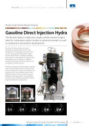
Simulation A of the final design predicted that scuffing would not be a problem. This was<br />
confirmed by a hot scuff engine test at maximum power output conditions. Simulation B of the<br />
final design predicted that the wear pattern on the skirt was suitable. This was again confirmed<br />
by the engine test. Figures 1 and 2 compare the wear patterns from the <strong>PISDYN</strong> simulation and<br />
from the hot scuff engine test respectively. The two patterns are quite similar apart from a wear<br />
region in the lower part of the skirt around the thrust plane, which was not predicted by the<br />
simulation.<br />
6 of 13
SIMULATI<strong>ON</strong> <strong>OF</strong> <strong>EFFECT</strong> <strong>OF</strong> <strong>USING</strong> L<strong>ON</strong>GER C<strong>ON</strong>NECTING ROD<br />
To simulate how using the proposed longer connecting rod would affect the performance of the<br />
designed piston required changing only four parameters in the input deck of the existing<br />
<strong>PISDYN</strong> models: the connecting rod length in the ENGINE section of the input deck and three<br />
geometric and inertial parameters in the ROD section of the input deck.<br />
Quietness evaluation<br />
As seen by figures 3 and 4, the simulations predicted that using the longer connecting rod would<br />
have little effect on noise during operating conditions that could cause “croaking”. The<br />
simulation showed however, that increasing the connecting rod length is likely to increase<br />
“rattle” noise. As illustrated by Figure 5, the maximum impact power per unit area of the skirt<br />
against the liner – the main quantity used to examine noise - was 230% times higher if the longer<br />
connecting rod was used. The kinetic energy transfer from the skirt to the cylinder during the<br />
slap causing “rattle” noise (shown by the drop from the peak in Figure 6) was predicted to be<br />
30% times higher if the longer connecting is used. Note, that the simulation showed that land<br />
impact with the bore would not occur during “rattle” conditions even if the longer connecting rod<br />
is used.<br />
If the maximum skirt-liner contact power per unit area is assumed to be representative of noise<br />
power, then the simulations predict that using the longer connecting rod would approximately<br />
increase “rattle” noise by 5.2 decibels. Such an increase in decibel level will be noticeable by the<br />
human ear (a 10 decibel increase in noise is felt by the human ear as about twice as loud).<br />
However, since the original engine was very quiet this may not be a problem.<br />
7 of 13
Wear and friction simulation<br />
Simulation type A showed that increasing the connecting rod length would reduce skirt friction<br />
loss by 1.0%. The maximum instantaneous wear load and maximum cumulative wear load were<br />
also predicted to be lower if the longer connecting rod is used, so scuffing or excessive wear<br />
should not occur if the longer conrod is used.<br />
The wear pattern predicted by simulation type B if the longer connecting rod is used is shown in<br />
Figure 7. This is clearly suitable and as seen by comparison with Figures 1 and 2, quite<br />
comparable to that produced when the original connecting rod was used.<br />
C<strong>ON</strong>CLUSI<strong>ON</strong>S<br />
The conclusions of the feasibility study using <strong>PISDYN</strong> of the effect on piston performance of<br />
increasing the connecting rod length by 7.9% in the particular four-cylinder petrol engine are:<br />
1. There will not be a danger of piston scuffing and the wear pattern will have little change.<br />
2. There will be little change in skirt frictional power loss.<br />
3. There will be little change in “croak” noise.<br />
4. There will be a significant increase in “rattle” noise amounting to about five decibels.<br />
Given the piston was found to be very quiet under “rattle” conditions when the original<br />
conrod was used, it is possible that the “rattle” noise with the new connecting rod will<br />
still be acceptable.<br />
The broader conclusions of this work are that:<br />
1. The <strong>PISDYN</strong> simulation package can be used to successfully optimise skirt profile, skirt<br />
contour, pin offset and other piston specifications to meet quietness, wear resistance,<br />
friction and durability design requirements.<br />
8 of 13
2. Once a <strong>PISDYN</strong> simulation model has been validated by an engine test, modifications to<br />
piston and engine specifications can easily be accounted for in the model and new<br />
simulations performed.<br />
ACKNOWLEDGEMENTS<br />
The authors would like to thank Nigel Tait for his assistance in writing this paper and Hung<br />
Nguyen for performing the initial simulation work for the piston design.<br />
9 of 13
Figure 1. Predicted wear pattern on thrust side of skirt in original engine. Regions of greatest<br />
wear are in red.<br />
Figure 2. Wear pattern of thrust side of skirt in original engine following hot scuff test.<br />
10 of 13
Comparison of Skirt-Liner Impact Power during "Croak" Condition<br />
Non-dimensional<br />
Power/Area Units<br />
1.2<br />
1<br />
0.8<br />
0.6<br />
0.4<br />
0.2<br />
0<br />
-150 -120 -90 -60 -30 0 30 60 90 120 150 180<br />
Compression<br />
TDC<br />
Expansion<br />
Crank Angle<br />
Existing conrod<br />
Longer conrod<br />
Figure 3. Simulated effect of increasing connecting rod length on power of skirt impacts with liner<br />
during operating conditions conducive to “croak” noise.<br />
Comparison of Piston Secondary Kinetic Energy during<br />
"Croak" Condition<br />
Non-dimensional energy<br />
units<br />
1.2<br />
1<br />
0.8<br />
0.6<br />
0.4<br />
0.2<br />
0<br />
-150 -120 -90 -60 -30 0 30 60 90 120 150 180<br />
Compression<br />
TDC<br />
Expansion<br />
Crank Angle<br />
existing conrod<br />
longer conrod<br />
Figure 4. Simulated effect of increasing connecting rod length on kinetic energy of skirt impacts with<br />
liner during operating conditions conducive to “croak” noise.<br />
11 of 13
C o m p ariso n S kirt-L in er Im p act P o w er d u rin g<br />
"R attle" C o n d itio n<br />
Non-dimensional<br />
Power/Area Units<br />
5<br />
4<br />
3<br />
2<br />
1<br />
0<br />
-150 -120 -90 -60 -30 0<br />
Compression<br />
TDC<br />
Crank Angle<br />
Existing conrod<br />
Longer conrod<br />
Figure 5. Simulated effect of increasing connecting rod length on power of skirt impacts with liner<br />
during operating conditions conducive to “rattle” noise.<br />
Comparison of Piston Secondary Kinetic Energy<br />
during "Rattle Condition"<br />
Non-dimensional energy<br />
units<br />
1.50E+00<br />
1.00E+00<br />
5.00E-01<br />
0.00E+00<br />
-150 -120 -90 -60 -30 0<br />
Compression<br />
TDC<br />
Crank Angle<br />
Existing conrod<br />
Longer conrod<br />
Figure 6. Simulated effect of increasing connecting rod length on kinetic energy of skirt impacts with<br />
liner during operating conditions conducive to “rattle” noise.<br />
12 of 13
Figure 7. Predicted wear pattern on thrust side of skirt if longer connecting rod was used.<br />
Regions of greatest wear are in red.<br />
13 of 13