Through-penetration Firestop Systems UL System No. F-C-1149 F ...
Through-penetration Firestop Systems UL System No. F-C-1149 F ...
Through-penetration Firestop Systems UL System No. F-C-1149 F ...

You also want an ePaper? Increase the reach of your titles
YUMPU automatically turns print PDFs into web optimized ePapers that Google loves.
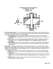
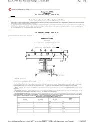
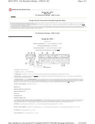
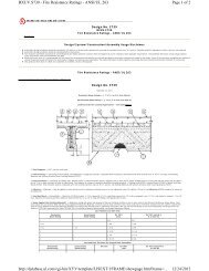
<strong>Through</strong>-<strong>penetration</strong> <strong>Firestop</strong> <strong><strong>System</strong>s</strong><br />
<strong>UL</strong> <strong>System</strong> <strong>No</strong>. F-C-<strong>1149</strong><br />
F Ratings - 1 and 2 Hr (See Item 1)<br />
T Rating - 1/4 Hr<br />
L Rating at Ambient - Less Than 1 CFM/Sq Ft<br />
2<br />
A<br />
3B<br />
1A<br />
2<br />
3B<br />
1B<br />
3A<br />
A<br />
1C<br />
3B<br />
1D<br />
SECTION A-A<br />
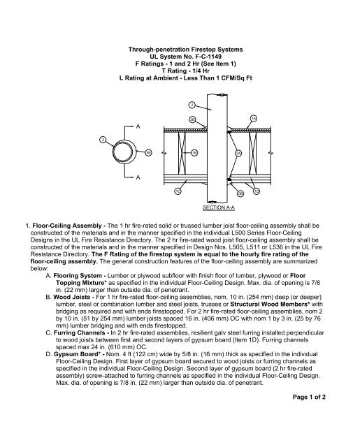
1. Floor-Ceiling Assembly - The 1 hr fire-rated solid or trussed lumber joist floor-ceiling assembly shall be<br />
constructed of the materials and in the manner specified in the individual L500 Series Floor-Ceiling<br />
Designs in the <strong>UL</strong> Fire Resistance Directory. The 2 hr fire-rated wood joist floor-ceiling assembly shall be<br />
constructed of the materials and in the manner specified in Design <strong>No</strong>s. L505, L511 or L536 in the <strong>UL</strong> Fire<br />
Resistance Directory. The F Rating of the firestop system is equal to the hourly fire rating of the<br />
floor-ceiling assembly. The general construction features of the floor-ceiling assembly are summarized<br />
below:<br />
A. Flooring <strong>System</strong> - Lumber or plywood subfloor with finish floor of lumber, plywood or Floor<br />
Topping Mixture* as specified in the individual Floor-Ceiling Design. Max. dia. of opening is 7/8<br />
in. (22 mm) larger than outside dia. of penetrant.<br />
B. Wood Joists - For 1 hr fire-rated floor-ceiling assemblies, nom. 10 in. (254 mm) deep (or deeper)<br />
lumber, steel or combination lumber and steel joists, trusses or Structural Wood Members* with<br />
bridging as required and with ends firestopped. For 2 hr fire-rated floor-ceiling assemblies, nom 2<br />
by 10 in. (51 by 254 mm) lumber joists spaced 16 in. (406 mm) OC with nom 1 by 3 in. (25 by 76<br />
mm) lumber bridging and with ends firestopped.<br />
C. Furring Channels - In 2 hr fire-rated assemblies, resilient galv steel furring installed perpendicular<br />
to wood joists between first and second layers of gypsum board (Item 1D). Furring channels<br />
spaced max 24 in. (610 mm) OC.<br />
D. Gypsum Board* - <strong>No</strong>m. 4 ft (122 cm) wide by 5/8 in. (16 mm) thick as specified in the individual<br />
Floor-Ceiling Design. First layer of gypsum board secured to wood joists or furring channels as<br />
specified in the individual Floor-Ceiling Design. Second layer of gypsum board (2 hr fire-rated<br />
assembly) screw-attached to furring channels as specified in the individual Floor-Ceiling Design.<br />
Max. dia. of opening is 7/8 in. (22 mm) larger than outside dia. of penetrant.<br />
Page 1 of 2
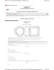
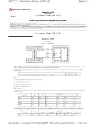
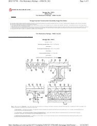
<strong>UL</strong> <strong>System</strong> F-C-<strong>1149</strong> continued…<br />
1.1 Chase Wall - (Optional, not shown) - The through penetrants (Item <strong>No</strong>. 2) may be routed through a firerated<br />
single, double or staggered wood stud/gypsum wallboard chase wall having a fire rating consistent<br />
with that of the floor-ceiling assembly. The chase wall shall be constructed of the materials and in the<br />
manner specified in the individual U300 Series Wall and Partition Designs in the <strong>UL</strong> Fire Resistance<br />
Directory and shall include the following construction features:<br />
A. Studs - <strong>No</strong>m. 2 by 6 in. (51 by 152 mm) or double nom 2 by 4 in. (51 by 102 mm) lumber studs.<br />
B. Sole Plate - <strong>No</strong>m. 2 by 6 in. (51 by 152 mm) or parallel 2 by 4 in. (51 by 102 mm) lumber plates,<br />
tightly butted. Max. dia. of opening is 3 in. (76 mm).<br />
C. Top Plate - The double top plate shall consist of two nom 2 by 6 in. (51 by 152 mm) or two sets of<br />
parallel 2 by 4 in. (51 by 102 mm) lumber plates, tightly butted. Max. dia. of opening is 3 in. (76<br />
mm).<br />
D. Gypsum Board* - Thickness, type, number of layers and fasteners shall be as specified in<br />
individual Wall and Partition Design.<br />
2. <strong>Through</strong> Penetrants - One metallic pipe, conduit or tubing to be installed either concentrically or<br />
eccentrically within the firestop system. The space between pipes, conduits or tubing and periphery of<br />
opening shall be min. 0 in. (point contact) to max. 7/8 in. (22 mm). Pipe, conduit or tubing to be rigidly<br />
supported on both sides of floor or wall assembly. The following types and sizes of metallic pipes, conduits<br />
or tubing may be used:<br />
A. Steel Pipe - <strong>No</strong>m 8 in. (203 mm) dia. (or smaller) Schedule 40 (or heavier) steel pipe.<br />
B. Iron Pipe - <strong>No</strong>m. 8 in. (203 mm) dia. (or smaller) cast or ductile iron pipe.<br />
C. Conduit - <strong>No</strong>m. 4 in. (102 mm) dia. (or smaller) steel electrical metallic tubing or nom 6 in. dia. (or<br />
smaller) steel conduit.<br />
D. Copper Tubing - <strong>No</strong>m. 4 in. (102 mm) dia. (or smaller) Type L (or heavier) copper tubing.<br />
E. Copper Pipe - <strong>No</strong>m. 4 in. (102 mm) dia. (or smaller) Regular (or heavier) copper pipe.<br />
3. <strong>Firestop</strong> <strong>System</strong> - The firestop system shall consist of the following:<br />
A. Packing Material - (Optional) - Foam backer rod firmly packed into opening as a permanent form.<br />
Packing material to be recessed from top surface of floor or sole plate and bottom surface of<br />
ceiling or lower top plate as required to accommodate the required thickness of fill material.<br />
B. Fill, Void or Cavity Material* - Caulk - Min. 5/8 in. (16 mm) thickness of fill material applied within<br />
the annulus, flush with top surface of the floor or sole plate and bottom surface of the ceiling or<br />
lower top plate. Additional fill material to be installed such that a min. 1/2 in. (13 mm) crown is<br />
formed around the penetrating item and lapping 1-1/4 in. (32 mm) beyond the periphery of the<br />
opening.<br />
A/D FIRE PROTECTION SYSTEMS INC - A/D FIREBARRIER Intumescent Sealant<br />
*Bearing the <strong>UL</strong> Classification Mark