Airport Master Plan - City of Riverside
Airport Master Plan - City of Riverside
Airport Master Plan - City of Riverside

You also want an ePaper? Increase the reach of your titles
YUMPU automatically turns print PDFs into web optimized ePapers that Google loves.
side Air<br />
Ri<br />
<strong>Riverside</strong> <strong>Airport</strong><br />
t<br />
AIRPORT MASTER PLAN
AIRPORT MASTER PLAN<br />
for<br />
RIVERSIDE AIRPORT<br />
<strong>Riverside</strong>, California<br />
Prepared for the<br />
CITY OF RIVERSIDE<br />
by<br />
C<strong>of</strong>fman Associates, Inc.<br />
Approved by the <strong>City</strong> <strong>of</strong> <strong>Riverside</strong> <strong>City</strong> Council<br />
August 25, 2009<br />
Printed Final January 2010<br />
“The preparation <strong>of</strong> this docum ent m ay have been supported, in part, through the A irport<br />
Improvem ent Program financial assistance from the Federal Aviation A dm inistration (Project<br />
Number3-06-0200-23) as provided under Title 49,United States Code,Section 47104. The<br />
contents do notnecessarily reflectthe <strong>of</strong>ficialview s orpolicy <strong>of</strong>the FA A . A cceptance <strong>of</strong>this<br />
reportby the FA A does notin any way constitute a commitmenton the part<strong>of</strong>the United States<br />
to participate in any developm ent depicted therein nor does it indicate that the proposed<br />
developm entis environm entally acceptable in accordance with appropriate public law s.”
TABLE OF CONTENTS
RIVERSIDE AIRPORT<br />
<strong>Riverside</strong>, California<br />
<strong>Airport</strong> <strong>Master</strong> <strong>Plan</strong><br />
INTRODUCTION<br />
MASTER PLAN GOALS AND OBJECTIVES ................................................... ii<br />
MASTER PLAN ELEMENT AND PROCESS .................................................. iii<br />
COORDINATION .............................................................................................. iv<br />
Baseline Assumptions ............................................................................. iv<br />
CONCLUSION .................................................................................................... v<br />
Chapter One<br />
INVENTORY<br />
AIRPORT SETTING AND ADMINISTRATION ............................................ 1-2<br />
Ground Transportation ......................................................................... 1-2<br />
<strong>Airport</strong> Administration ......................................................................... 1-3<br />
Regional Climate ................................................................................... 1-3<br />
AREA LAND USE ............................................................................................ 1-4<br />
<strong>Riverside</strong> County <strong>Airport</strong> Land Use<br />
Compatibility <strong>Plan</strong> .............................................................................. 1-4<br />
AIRPORT SYSTEM PLANNING ROLE ......................................................... 1-5<br />
Southern California Association <strong>of</strong> Governments (SCAG)<br />
General Aviation System <strong>Plan</strong> ........................................................... 1-6<br />
California Aviation System <strong>Plan</strong> (CASP) ............................................. 1-7<br />
Previous <strong>Airport</strong> <strong>Master</strong> <strong>Plan</strong> ............................................................... 1-7<br />
AIRSIDE FACILITIES .................................................................................... 1-9<br />
Runways .............................................................................................. 1-10
Chapter One (Continued)<br />
Taxiways .............................................................................................. 1-10<br />
Pavement Markings ............................................................................ 1-10<br />
Airfield Lighting .................................................................................. 1-11<br />
Weather And Communication Aids .................................................... 1-12<br />
Navigational Aids ................................................................................ 1-13<br />
Area Airspace ...................................................................................... 1-14<br />
Instrument Approach Procedures ...................................................... 1-16<br />
<strong>Airport</strong> Traffic Control Tower ............................................................. 1-19<br />
Helipad ................................................................................................ 1-19<br />
LANDSIDE FACILITIES .............................................................................. 1-19<br />
<strong>Airport</strong> Businesses .............................................................................. 1-19<br />
Aircraft Parking Apron ....................................................................... 1-20<br />
Aircraft Hangar Facilities ................................................................... 1-20<br />
Automobile Parking ............................................................................ 1-21<br />
Aircraft Wash Facility ......................................................................... 1-21<br />
Aircraft Rescue and Firefighting (ARFF) ........................................... 1-21<br />
<strong>Airport</strong> Maintenance ........................................................................... 1-22<br />
Utilities ................................................................................................ 1-22<br />
Fuel Facilities ...................................................................................... 1-22<br />
Fencing ................................................................................................ 1-22<br />
Additional <strong>Airport</strong> Documentation ..................................................... 1-23<br />
REGIONAL AIRPORTS ................................................................................ 1-23<br />
AIRPORT CAPITAL IMPROVEMENT HISTORY ...................................... 1-25<br />
HISTORICAL AIRPORT ACTIVITY ............................................................ 1-26<br />
Annual Operations .............................................................................. 1-26<br />
Based Aircraft...................................................................................... 1-28<br />
Air Service ........................................................................................... 1-28<br />
ENVIRONMENTAL INVENTORY ............................................................... 1-29<br />
Wetlands .............................................................................................. 1-29<br />
Floodplains .......................................................................................... 1-29<br />
Water Supply and Quality .................................................................. 1-30<br />
Biotic Resources .................................................................................. 1-30<br />
Air Quality ........................................................................................... 1-32<br />
Environmental Justice ........................................................................ 1-33<br />
Department <strong>of</strong> Transportation Act: Section 4(f) ............................... 1-33<br />
Historical and Cultural Resources ..................................................... 1-33<br />
SUMMARY ..................................................................................................... 1-34<br />
DOCUMENT SOURCES ............................................................................... 1-34
Chapter Two<br />
FORECASTS<br />
AVIATION TRENDS AND PROJECTIONS .................................................. 2-2<br />
National Trends .................................................................................... 2-2<br />
General Aviation ................................................................................... 2-3<br />
Regional and Local Trends and Projections ......................................... 2-8<br />
SERVICE AREA ............................................................................................ 2-10<br />
SOCIOECONOMIC CHARACTERISTICS ................................................... 2-11<br />
Population ............................................................................................ 2-11<br />
Employment ........................................................................................ 2-12<br />
Income .................................................................................................. 2-13<br />
FORECASTING APPROACH ....................................................................... 2-14<br />
GENERAL AVIATION FORECASTS ........................................................... 2-15<br />
Registered Aircraft Forecast ............................................................... 2-15<br />
Based Aircraft Forecasts ..................................................................... 2-18<br />
Based Aircraft Fleet Mix ..................................................................... 2-20<br />
ANNUAL OPERATIONS .............................................................................. 2-21<br />
Itinerant Operations ........................................................................... 2-22<br />
Local Operations ................................................................................. 2-24<br />
Air Taxi Operations ............................................................................. 2-24<br />
Military ................................................................................................ 2-26<br />
Operations Adjustment and Summary .............................................. 2-26<br />
PEAKING CHARACTERISTICS .................................................................. 2-26<br />
ANNUAL INSTRUMENT APPROACHES ................................................... 2-27<br />
SUMMARY ..................................................................................................... 2-28<br />
Chapter Three<br />
AIRPORT FACILITY REQUIREMENTS<br />
PLANNING HORIZONS ................................................................................. 3-1<br />
AIRFIELD CAPACITY .................................................................................... 3-3<br />
Factors Affecting Annual Service Volume ........................................... 3-3<br />
Calculation <strong>of</strong> Annual Service Volume ................................................. 3-6<br />
CRITICAL AIRCRAFT .................................................................................... 3-8<br />
Current Critical Aircraft ....................................................................... 3-9<br />
Future Critical Aircraft ....................................................................... 3-11<br />
AIRFIELD REQUIREMENTS ...................................................................... 3-12<br />
Design Standards ................................................................................ 3-12<br />
Runways .............................................................................................. 3-16<br />
Taxiways .............................................................................................. 3-24<br />
Instrument Navigation Aids ............................................................... 3-25<br />
Visual Navigation Aids ....................................................................... 3-26<br />
Weather Reporting Aids ...................................................................... 3-26
Chapter Three (Continued)<br />
Airfield Lighting and Marking ........................................................... 3-26<br />
<strong>Airport</strong> Traffic Control Tower ............................................................. 3-27<br />
LANDSIDE REQUIREMENTS ..................................................................... 3-27<br />
Hangars ............................................................................................... 3-28<br />
Aircraft Parking Apron ....................................................................... 3-29<br />
General Aviation Terminal Facilities ................................................. 3-30<br />
SUPPORT REQUIREMENTS ....................................................................... 3-31<br />
Automobile Parking ............................................................................ 3-31<br />
Fuel Storage ........................................................................................ 3-32<br />
Aircraft Rescue and Firefighting (ARFF) ........................................... 3-33<br />
<strong>Airport</strong> Maintenance Building ............................................................ 3-33<br />
Utilities ................................................................................................ 3-34<br />
Vehicle Access ...................................................................................... 3-34<br />
Security ................................................................................................ 3-34<br />
Fractional Jet Operator Security Requirements ............................... 3-39<br />
SUMMARY ..................................................................................................... 3-40<br />
Chapter Four<br />
ALTERNATIVES<br />
AIRPORT DEVELOPMENT OBJECTIVES ................................................... 4-2<br />
AIRSIDE PLANNING ISSUES ....................................................................... 4-3<br />
AIRSIDE DEVELOPMENT ALTERNATIVES .............................................. 4-3<br />
Instrument Approach Impact ............................................................... 4-4<br />
Runway/Taxiway Separation Analysis ................................................. 4-5<br />
Runway Safety Area (RSA) Considerations ......................................... 4-6<br />
ARC B-II Safety Area .......................................................................... 4-16<br />
Runway Length and Runway Protection Zones ................................. 4-17<br />
LANDSIDE PLANNING ISSUES ................................................................. 4-19<br />
Vehicular Access and Parking ............................................................ 4-21<br />
Terminal Area Development Alternatives ......................................... 4-21<br />
North Side Development Alternatives ............................................... 4-23<br />
Landside Summary ............................................................................. 4-24<br />
ALTERNATIVES SUMMARY ...................................................................... 4-25<br />
Chapter Five<br />
RECOMMENDED MASTER PLAN CONCEPT<br />
RECOMMENDED MASTER PLAN CONCEPT ............................................ 5-2<br />
Airside Concept ..................................................................................... 5-2
Chapter Five (Continued)<br />
Landside Concept .................................................................................. 5-9<br />
SUMMARY ..................................................................................................... 5-12<br />
Chapter Six<br />
CAPITAL IMPROVEMENT PROGRAM<br />
AIRPORT DEVELOPMENT SCHEDULES<br />
AND COST SUMMARIES ............................................................................. 6-1<br />
Short Term Improvements .................................................................... 6-3<br />
Intermediate Term Improvements ....................................................... 6-5<br />
Long Term Improvements .................................................................... 6-6<br />
Capital Improvement Summary ........................................................... 6-7<br />
CAPITAL IMPROVEMENT FUNDING SOURCES ...................................... 6-8<br />
Federal Grants ...................................................................................... 6-8<br />
State Aid To <strong>Airport</strong>s ............................................................................ 6-9<br />
Local Funding ...................................................................................... 6-10<br />
SUMMARY ..................................................................................................... 6-12<br />
EXHIBITS<br />
IA<br />
MASTER PLAN PROCESS ................................................... after page iv<br />
1A LOCATION MAP ................................................................ after page 1-2<br />
1B EXISTING LAND USE ....................................................... after page 1-4<br />
1C RIVERSIDE LAND USE POLICY MAP ............................ after page 1-4<br />
1D AIRPORT LAND USE COMPATIBILITY PLAN .............. after page 1-6<br />
1E 1998 MASTER PLAN CONCEPT ...................................... after page 1-8<br />
1F EXISTING FACILITIES ................................................... after page 1-10<br />
1G AIRSPACE CLASSIFICATION ........................................ after page 1-14<br />
1H VICINITY AIRSPACE MAP ............................................. after page 1-16<br />
1J NOISE ABATEMENT PROCEDURES<br />
AND TRAFFIC PATTERNS ........................................... after page 1-20<br />
2A U.S. ACTIVE GENERAL AVIATION<br />
AIRCRAFT FORECASTS ................................................. after page 2-8<br />
2B SCAG AIRPORT “RIPPLE EFFECT” .............................. after page 2-10<br />
2C PRIMARY AIRPORT SERVICE AREA............................ after page 2-12<br />
2D WESTERN RIVERSIDE COUNTY<br />
REGISTERED AIRCRAFT FORECAST ........................ after page 2-18<br />
2E BASED AIRCRAFT FORECAST SUMMARY ................. after page 2-20
EXHIBITS (Continued)<br />
2F GENERAL AVIATION OPERATIONS FORECAST ....... after page 2-24<br />
2G FORECAST SUMMARY ................................................... after page 2-28<br />
3A AIRFIELD CAPACITY FACTORS ..................................... after page 3-4<br />
3B AIRFIELD CAPACITY ....................................................... after page 3-8<br />
3C AIRPORT REFERENCE CODES ..................................... after page 3-10<br />
3D RUNWAY SAFETY AREAS ............................................. after page 3-12<br />
3E WINDROSE ....................................................................... after page 3-16<br />
3F AIRFIELD FACILITY REQUIREMENTS ....................... after page 3-40<br />
3G LANDSIDE FACILITY REQUIREMENTS ..................... after page 3-40<br />
4A PLANNING ISSUES ........................................................... after page 4-4<br />
4B RSA ALTERNATIVE A PROVIDE FULL RSA ............... after page 4-10<br />
4C RSA ALTERNATIVE B RUNWAY SHIFT ...................... after page 4-10<br />
4D RSA ALTERNATIVE E DECLARED DISTANCES ........ after page 4-12<br />
4E RSA ALTERNATIVE F ..................................................... after page 4-14<br />
4F RUNWAY EXTENSION/SHIFT CONSIDERATIONS .... after page 4-20<br />
4G TERMINAL AREA ALTERNATIVES .............................. after page 4-22<br />
4H NORTH SIDE DEVELOPMENT ALTERNATIVES ....... after page 4-24<br />
5A RECOMMENDED MASTER PLAN CONCEPT................ after page 5-2<br />
6A CAPITAL IMPROVEMENT PROGRAM ........................... after page 6-4<br />
6B AIRPORT DEVELOPMENT STAGING ............................ after page 6-4<br />
Appendix A<br />
GLOSSARY OF TERMS<br />
Appendix B<br />
AIRPORT PLANS<br />
Appendix C<br />
ENVIRONMENTAL EVALUATION<br />
Appendix D<br />
ECONOMIC BENEFIT STUDY<br />
Appendix E<br />
FAA FORECAST APPROVAL LETTER
INTRODUCTION
RIVERSIDE AIRPORT<br />
MASTER PLAN<br />
Introduction<br />
This update <strong>of</strong> the <strong>Riverside</strong> <strong>Airport</strong><br />
(RAL) <strong>Master</strong> <strong>Plan</strong> has been undertaken<br />
to evaluate the airport’s capabilities and<br />
role, to review forecasts <strong>of</strong> future<br />
aviation demand, and to plan for the<br />
timely development <strong>of</strong> new or expanded<br />
facilities that may be required to meet<br />
that demand. The ultimate goal <strong>of</strong> the<br />
master plan is to provide systematic<br />
guidelines for the airport’s overall<br />
development, maintenance, and operation.<br />
The master plan is intended to be a proactive<br />
document which identifies and then plans<br />
for future facility needs well in advance<br />
<strong>of</strong> the actual need for the facilities. This is<br />
done to ensure that the <strong>City</strong> <strong>of</strong> <strong>Riverside</strong>,<br />
as the airport sponsor, can coordinate project<br />
approvals, design, financing, and construction<br />
to avoid experiencing detrimental effects<br />
due to inadequate facilities.<br />
An important result <strong>of</strong> the master plan is<br />
reserving sufficient areas for future<br />
facility needs. This protects development<br />
areas and ensures they will be readily<br />
available when required to meet demand.<br />
The intended result is a development<br />
concept which outlines the proposed<br />
uses for all areas <strong>of</strong> airport property.<br />
The <strong>City</strong> <strong>of</strong> <strong>Riverside</strong> recognizes the<br />
importance <strong>of</strong> air transportation to the<br />
community, as well as the unique<br />
challenges that operating an airport<br />
presents. The investment in an airport<br />
yields many benefits to the community<br />
and the region. With a sound and realistic<br />
master plan, the <strong>Riverside</strong> <strong>Airport</strong> can<br />
maintain its important link to the national<br />
air transportation system for the community<br />
and maintain the existing public and<br />
private investments in its facilities.<br />
i
MASTER PLAN GOALS<br />
AND OBJECTIVES<br />
The primary objective <strong>of</strong> the master<br />
plan is to provide the community and<br />
its leadership with guidance for operating<br />
the airport in a safe and efficient<br />
manner while planning for future demand<br />
levels. Accomplishing this objective<br />
requires a comprehensive evaluation<br />
<strong>of</strong> the existing airport and a determination<br />
<strong>of</strong> what actions should be<br />
taken to maintain a safe and reliable<br />
airport facility while meeting the aviation<br />
needs <strong>of</strong> the region. This master<br />
plan will provide a vision for the airport<br />
covering the next 20 years and, in<br />
some cases, beyond. With this vision,<br />
the <strong>City</strong> <strong>of</strong> <strong>Riverside</strong> will have advance<br />
notice <strong>of</strong> potential future airport<br />
funding needs so that appropriate<br />
steps can be taken to ensure that adequate<br />
funds are budgeted and<br />
planned.<br />
Specific objectives <strong>of</strong> the <strong>Riverside</strong><br />
<strong>Airport</strong> <strong>Master</strong> <strong>Plan</strong> Update are:<br />
To preserve and protect public and<br />
private investments in existing<br />
airport facilities;<br />
To enhance the safety <strong>of</strong> aircraft<br />
operations;<br />
To be reflective <strong>of</strong> community and<br />
regional goals, needs, and plans;<br />
To ensure that future development<br />
is environmentally compatible;<br />
To establish a schedule <strong>of</strong> development<br />
priorities designed to meet<br />
forecast aviation demand;<br />
To develop a plan that is responsive<br />
to air transportation demands;<br />
To develop an orderly plan for use<br />
<strong>of</strong> the airport;<br />
To meet Federal Aviation Administration<br />
(FAA) airport design standards;<br />
To coordinate this master plan<br />
with local, regional, state, and federal<br />
agencies, and;<br />
To develop active and productive<br />
public involvement throughout the<br />
planning process.<br />
The master plan will accomplish these<br />
objectives by carrying out the following:<br />
Determining projected needs <strong>of</strong><br />
airport users through the year<br />
2027;<br />
Analyzing socioeconomic factors<br />
likely to affect air transportation<br />
demand for the airport;<br />
Identifying potential existing and<br />
future land acquisition needs;<br />
Evaluating future airport facility<br />
development alternatives which<br />
will optimize airport capacity and<br />
aircraft safety;<br />
ii
Developing a realistic, commonsense<br />
plan for the use and/or expansion<br />
<strong>of</strong> the airport;<br />
Present environmental consideration<br />
associated with the recommended<br />
development alternatives;<br />
Produce current and accurate airport<br />
base maps and <strong>Airport</strong> Layout<br />
<strong>Plan</strong>s.<br />
MASTER PLAN<br />
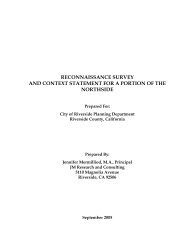
ELEMENTS AND PROCESS<br />
The <strong>Riverside</strong> <strong>Airport</strong> <strong>Master</strong> <strong>Plan</strong><br />
Update is being prepared in a systematic<br />
fashion following FAA and California<br />
Department <strong>of</strong> Transportation<br />
Division <strong>of</strong> Aeronautics (Caltrans)<br />
guidelines and industry-accepted principles<br />
and practices, as shown on Exhibit<br />
IA. The master plan has six<br />
chapters that are intended to assist in<br />
the discovery <strong>of</strong> future facility needs<br />
and provide the supporting rationale<br />
for their implementation.<br />
Chapter One - Inventory summarizes<br />
the inventory efforts. The inventory<br />
efforts are focused on collecting<br />
and assembling relevant data pertaining<br />
to the airport and the area it<br />
serves. Information is collected on existing<br />
airport facilities and operations.<br />
Local economic and demographic data<br />
is collected to define the local growth<br />
trends. <strong>Plan</strong>ning studies which may<br />
have relevance to the master plan are<br />
also collected.<br />
Chapter Two - Forecasts examines<br />
the potential aviation demand at the<br />
airport. The analysis utilizes local socioeconomic<br />
information, as well as<br />
national air transportation trends, to<br />
quantify the levels <strong>of</strong> aviation activity<br />
which can reasonably be expected to<br />
occur at <strong>Riverside</strong> <strong>Airport</strong> through the<br />
year 2027. The results <strong>of</strong> this effort<br />
are used to determine the types and<br />
sizes <strong>of</strong> facilities which will be required<br />
to meet the projected aviation<br />
demand at the airport through the<br />
planning period.<br />
Chapter Three - Facility Requirements<br />
comprises the demand capacity<br />
and facility requirements analyses.<br />
The intent <strong>of</strong> this analysis is to compare<br />
the existing facility capacities to<br />
forecast aviation demand and determine<br />
where deficiencies in capacities<br />
(as well as excess capacities) may exist.<br />
Where deficiencies are identified,<br />
the size and type <strong>of</strong> new facilities to<br />
accommodate the demand are identified.<br />
The airfield analysis focuses on<br />
improvements needed to safely serve<br />
the type <strong>of</strong> aircraft expected to operate<br />
at the airport in the future, as well as<br />
navigational aids to increase the safety<br />
and efficiency <strong>of</strong> operations. This<br />
element also examines the general<br />
aviation terminal, hangar, apron, and<br />
support needs.<br />
Chapter Four - Alternatives considers<br />
a variety <strong>of</strong> solutions to accommodate<br />
the projected facility needs.<br />
This element proposes various facility<br />
and site plan configurations which can<br />
meet the projected facility needs. An<br />
analysis is completed to identify the<br />
strengths and weaknesses <strong>of</strong> each<br />
proposed development alternative,<br />
with the intention <strong>of</strong> determining a<br />
single direction for development.<br />
iii
Chapter Five - <strong>Airport</strong> <strong>Plan</strong>s provides<br />
both a graphic and narrative description<br />
<strong>of</strong> the recommended plan for<br />
the use, development, and operation <strong>of</strong><br />
the airport. An environmental overview<br />
is also provided. The master<br />
plan also includes the <strong>Airport</strong> Layout<br />
<strong>Plan</strong> (ALP) and detailed technical<br />
drawings depicting related airspace,<br />
land use, and property data. These<br />
drawings are used by the FAA and<br />
Caltrans in determining grant eligibility<br />
and funding.<br />
Chapter Six - Financial <strong>Plan</strong> focuses<br />
on the capital needs program which<br />
defines the schedules, costs, and funding<br />
sources for the recommended development<br />
projects.<br />
COORDINATION<br />
The <strong>Riverside</strong> <strong>Airport</strong> <strong>Master</strong> <strong>Plan</strong><br />
Update is <strong>of</strong> interest to many within<br />
the local community. This includes local<br />
citizens, community organizations,<br />
airport users, airport tenants, areawide<br />
planning agencies, and aviation<br />
organizations.<br />
As an important component <strong>of</strong> the regional,<br />
state, and national aviation<br />
systems, the <strong>Riverside</strong> <strong>Airport</strong> is <strong>of</strong><br />
importance to both state and federal<br />
agencies responsible for overseeing air<br />
transportation.<br />
To assist in the development <strong>of</strong> the<br />
master plan, the airport administration<br />
has identified a group <strong>of</strong> community<br />
members and aviation interest<br />
groups to act in an advisory role in the<br />
development <strong>of</strong> the master plan.<br />
Members <strong>of</strong> the <strong>Plan</strong>ning Advisory<br />
Committee (PAC) will review phase<br />
reports and provide comments<br />
throughout the study to help ensure<br />
that a realistic, viable plan is developed.<br />
To assist in the review process, draft<br />
chapters will be prepared at the various<br />
milestones in the planning<br />
process. The production <strong>of</strong> draft chapters<br />
allows for timely input and review<br />
during each step within the master<br />
plan to ensure that all master plan issues<br />
are fully addressed as the recommended<br />
program develops.<br />
BASELINE ASSUMPTIONS<br />
A study such as this typically requires<br />
some baseline assumptions that will<br />
be used throughout the analysis. The<br />
baseline assumptions for the <strong>Riverside</strong><br />
<strong>Airport</strong> <strong>Master</strong> <strong>Plan</strong> are listed below:<br />
<strong>Riverside</strong> <strong>Airport</strong> currently operates<br />
as a reliever airport in the<br />
greater Los Angeles metropolitan<br />
area, and in particular, to the Ontario<br />
International <strong>Airport</strong>.<br />
<strong>Riverside</strong> <strong>Airport</strong> will continue in<br />
its role as a reliever airport.<br />
Rialto Municipal <strong>Airport</strong> may close<br />
in the near term.<br />
The other publicly owned general<br />
aviation airports in the region will<br />
remain open for the foreseeable future.<br />
The airport will operate under the<br />
direction <strong>of</strong> the <strong>City</strong> <strong>of</strong> <strong>Riverside</strong><br />
throughout the planning period.<br />
iv
05MP11-IA-9/05/07<br />
• <strong>Airport</strong> Facilities<br />
• Airspace and Air Traffic Activity<br />
• Area Socioeconomic Data<br />
INVENTORY<br />
• Local <strong>Plan</strong>ning and Land Use<br />
• <strong>Airport</strong> Access and Parking,<br />
Utilities, and Aerial Photography<br />
FORECASTS<br />
• Based Aircraft and Fleet Mix<br />
• Annual Operations<br />
PLANNING<br />
ADVISORY<br />
COMMITTEE<br />
MEETING<br />
FACILITY REQUIREMENTS<br />
• Design Categories<br />
• Runway Length and Strength<br />
• Support Facilities<br />
• Taxiways<br />
• Hangar Facilities<br />
• Terminal Building<br />
• Aprons<br />
• Navigational Aids<br />
PHASE ONE<br />
REPORT<br />
PLANNING<br />
ADVISORY<br />
COMMITTEE<br />
MEETING<br />
AIRPORT ALTERNATIVES<br />
• Detailed <strong>Master</strong> <strong>Plan</strong> Facility<br />
and Land Use <strong>Plan</strong>s<br />
• Evaluate Development Scenarios<br />
- Airside - Landside<br />
RECOMMENDED DEVELOPMENT PLAN<br />
ENVIRONMENTAL OVERVIEW<br />
FINANCIAL PLAN<br />
• <strong>Airport</strong> Development Schedule<br />
• Cost Estimates<br />
• Funding Sources<br />
• Review/Evaluation <strong>of</strong> NEPA<br />
Environmental Categories<br />
• Noise Exposure<br />
PHASE TWO<br />
REPORT<br />
PLANNING<br />
ADVISORY<br />
COMMITTEE<br />
MEETING<br />
ECONOMIC BENEFIT ANALYSIS<br />
• Total Economic Benefits<br />
• Based Aircraft Benefits<br />
AIRPORT LAYOUT PLANS<br />
• <strong>Airport</strong> Layout <strong>Plan</strong><br />
• Landside Drawing<br />
• Airspace/Approach Drawings<br />
• Tax Benefits<br />
• Future Benefits<br />
• On-<strong>Airport</strong> Land Use <strong>Plan</strong><br />
• Property Map<br />
draft<br />
DRAFT FINAL<br />
REPORT<br />
FINAL<br />
MASTER PLAN<br />
REPORT<br />
EXECUTIVE<br />
SUMMARY<br />
BROCHURE<br />
Exhibit IA<br />
MASTER PLAN PROCESS
<strong>Riverside</strong> <strong>Airport</strong> intends to seek<br />
general aviation and corporate<br />
business aviation based tenants<br />
and transient operations.<br />
The aviation industry on the national<br />
level will grow as forecast by<br />
the FAA in its annual Aerospace<br />
Forecasts.<br />
Population and employment in the<br />
<strong>Riverside</strong> <strong>Airport</strong> service area will<br />
continue to grow as forecast by the<br />
Southern California Association <strong>of</strong><br />
Governments (SCAG), the Western<br />
<strong>Riverside</strong> County Council <strong>of</strong> Governments<br />
(WRCOG), and the <strong>City</strong><br />
<strong>of</strong> <strong>Riverside</strong>.<br />
CONCLUSION<br />
The master plan is evidence that the<br />
<strong>City</strong> <strong>of</strong> <strong>Riverside</strong> is committed to<br />
maintaining a first-class aviation facility<br />
providing general aviation services.<br />
The <strong>City</strong> recognizes the importance <strong>of</strong><br />
<strong>Riverside</strong> <strong>Airport</strong> to the community<br />
and the region, as well as the associated<br />
challenges inherent in providing<br />
for aviation needs in a growing regional<br />
environment. Maintaining a<br />
sound, flexible master plan will facilitate<br />
continued growth <strong>of</strong> the airport as<br />
a major economic asset for the community.<br />
v
Chapter One<br />
INVENTORY
RIVERSIDE AIRPORT<br />
MASTER PLAN<br />
Chapter One<br />
Inventory<br />
The initial step in the preparation <strong>of</strong> the<br />
airport master plan update for <strong>Riverside</strong><br />
<strong>Airport</strong> is the collection <strong>of</strong> information<br />
that will provide a basis for the analysis<br />
to be completed in subsequent chapters.<br />
For the master plan, information is<br />
gathered regarding not only the airport,<br />
but also the region it serves. This chapter<br />
will begin with an overview <strong>of</strong> the<br />
airport location, competing airports, and<br />
typical weather conditions. This will be<br />
followed by a discussion <strong>of</strong> demographic<br />
and socioeconomic factors relevant to the<br />
region. A comprehensive overview <strong>of</strong><br />
the national aviation system for general<br />
aviation airports and the role <strong>of</strong><br />
<strong>Riverside</strong> <strong>Airport</strong> in the national system<br />
are also presented. Finally, an inventory<br />
<strong>of</strong> the existing facilities at the airport will<br />
be discussed.<br />
The information outlined in this chapter<br />
was obtained through on-site inspections<br />
<strong>of</strong> the airport, including interviews with<br />
airport management, airport tenants, and<br />
representatives <strong>of</strong> various government<br />
agencies. Information was also obtained<br />
from existing studies. Additional<br />
information and documents were<br />
provided by the Federal Aviation<br />
Administration (FAA), <strong>Riverside</strong> County<br />
<strong>Airport</strong> Land Use Commission, the <strong>City</strong><br />
<strong>of</strong> <strong>Riverside</strong> - <strong>Plan</strong>ning and Development<br />
Departments, and the California<br />
Department <strong>of</strong> Transportation - Aeronautics<br />
Division (Caltrans). A complete list <strong>of</strong><br />
document sources is provided at the end<br />
<strong>of</strong> this chapter.<br />
1-1
AIRPORT SETTING<br />
AND ADMINISTRATION<br />
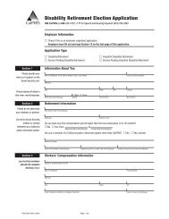
As depicted on Exhibit 1A, <strong>Riverside</strong><br />
<strong>Airport</strong> is located on approximately<br />
441 acres <strong>of</strong> property in the northwest<br />
portion <strong>of</strong> the <strong>City</strong> <strong>of</strong> <strong>Riverside</strong>, California.<br />
The airport is approximately<br />
six miles to the west/southwest <strong>of</strong> the<br />
<strong>City</strong> <strong>of</strong> <strong>Riverside</strong>’s government district.<br />
The <strong>City</strong> <strong>of</strong> <strong>Riverside</strong> is located<br />
in <strong>Riverside</strong> County in the greater Los<br />
Angeles basin and is approximately 50<br />
miles from downtown Los Angeles.<br />
The <strong>City</strong> <strong>of</strong> <strong>Riverside</strong> is located in a<br />
well-developed area and is adjacent to<br />
the cities <strong>of</strong> San Bernardino, Rancho<br />
Cucamonga, and Ontario to the north.<br />
To the west is the Cities <strong>of</strong> Moreno<br />
Valley and Chino and to the south is<br />
Corona.<br />
The airport is bordered on the north<br />
by Central Avenue, to the south by the<br />
Arlington Avenue, and to the west by<br />
Van Buren Boulevard. Each <strong>of</strong> these<br />
is an arterial road traversing the <strong>City</strong><br />
<strong>of</strong> <strong>Riverside</strong>. On the west, the airport<br />
is bordered by Hillside Avenue, a connector<br />
street.<br />
<strong>Airport</strong> Drive, extending from Arlington<br />
Avenue, is the main entrance to<br />
the airport. Flight Road provides terminal<br />
building access and access to<br />
airport facilities located southwest <strong>of</strong><br />
the primary runway. Gemende Drive<br />
provides access to general aviation<br />
services and the hangar storage building<br />
on the southeast side <strong>of</strong> the primary<br />
runway. An unnamed road leading<br />
to the new general aviation hangars is<br />
being constructed west <strong>of</strong> Runway 16-<br />
34 will extend east from Arlington<br />
1-2<br />
Avenue. Access from Central Avenue<br />
to the north leads to the hangar facility<br />
located to the east <strong>of</strong> Runway 16.<br />
GROUND TRANSPORTATION<br />
The <strong>Riverside</strong> Transit Agency (RTA)<br />
serves the <strong>City</strong> <strong>of</strong> <strong>Riverside</strong> and the<br />
western third <strong>of</strong> <strong>Riverside</strong> County, as<br />
far east as the <strong>City</strong> <strong>of</strong> Banning, approximately<br />
30 miles to the east <strong>of</strong> the<br />
<strong>City</strong> <strong>of</strong> <strong>Riverside</strong>. As <strong>of</strong> 2006, the RTA<br />
operates more than 230 vehicles, the<br />
majority <strong>of</strong> which are traditional<br />
busses on 39 fixed routes. Five commuter<br />
routes are provided and a Dial-<br />
A-Ride Service is available.<br />
The <strong>City</strong> <strong>of</strong> <strong>Riverside</strong> is served by<br />
Greyhound and Amtrak, both <strong>of</strong> which<br />
provide terminal facilities in downtown<br />
<strong>Riverside</strong>. Metrolink trains provide<br />
commuter rail service from western<br />
<strong>Riverside</strong> County to Los Angeles<br />
and Orange counties. The Pedley Metrolink<br />
station is approximately three<br />
miles to the northwest and the La<br />
Sierra station is approximately five<br />
miles southwest <strong>of</strong> the airport. The<br />
<strong>Riverside</strong> downtown station serves<br />
both Amtrak and Metrolink. Local<br />
transportation service providers include<br />
several taxi companies and charter<br />
van and bus lines.<br />
Union Pacific rail lines extend through<br />
the <strong>City</strong> <strong>of</strong> <strong>Riverside</strong>. One rail spur<br />
crosses Central Avenue, extending<br />
south to within approximately 475 feet<br />
<strong>of</strong> the Runway 9 end. This rail spur<br />
terminates near the intersection <strong>of</strong><br />
Van Buren Boulevard and Arlington<br />
Avenue. This spur primarily serves a<br />
lumber yard accessible from Arlington<br />
Avenue.
MAIN ST<br />
05MP11-1A-8/14/07<br />
MISSION BLVD<br />
215<br />
MARKET ST<br />
VAN BUREN<br />
60<br />
BLVD<br />
LIMONITE AVE<br />
Santa<br />
Anna<br />
RIVERSIDE<br />
AIRPORT<br />
River<br />
Regional<br />
Park<br />
UNIVERSITY AVE<br />
215<br />
Box Springs Mountain Park<br />
CENTRAL AVE<br />
ARLINGTON AVE<br />
LA SIERRA AVE<br />
MAGNOLIA<br />
91<br />
VICTORIA AVE<br />
Citrus<br />
Heritage<br />
Park<br />
ALESSANDRO<br />
RIVERSIDE<br />
Sycamore<br />
Canyon<br />
Park<br />
TRAUTWEIN<br />
BLVD<br />
RD<br />
MARCH<br />
AIR FORCE<br />
BASE<br />
60<br />
215<br />
VAN<br />
BUREN<br />
BLVD<br />
<strong>Riverside</strong><br />
Nat'l<br />
Cemetary<br />
Piru<br />
Simi Valley<br />
5<br />
Thousand Oaks<br />
Santa Monica<br />
405<br />
San Fernando<br />
101<br />
Beverly Hills<br />
Inglewood<br />
Redondo Beach<br />
Rancho Palos Verdes<br />
210<br />
Glendale<br />
110<br />
Acton<br />
<strong>City</strong> <strong>of</strong><br />
Los Angeles<br />
710<br />
Palmdale<br />
Altadena<br />
10<br />
Compton<br />
Norwalk<br />
Littlerock<br />
605<br />
Long Beach<br />
Huntington Beach<br />
Walnut<br />
La Mirada<br />
Newport Beach<br />
Wrightwood<br />
La Verne<br />
Anaheim<br />
Garden Grove<br />
Santa Ana<br />
405<br />
San Juan Capistrano<br />
210<br />
Ontario<br />
Chino<br />
15<br />
215<br />
Corona<br />
Rialto<br />
Colton<br />
15<br />
Lakeland<br />
Village<br />
Mission Viejo<br />
Victorville<br />
Hesperia<br />
Big Bear <strong>City</strong><br />
Big Bear Lake<br />
Running Springs<br />
San Bernardino<br />
<strong>Riverside</strong><br />
Beaumont<br />
Lakeview<br />
Perris<br />
Hemet<br />
Winchester<br />
Sedco Hills<br />
Murrieta<br />
Redlands<br />
Yucaipa<br />
10<br />
Banning<br />
Murrieta Hot Springs<br />
Temecula<br />
Palm<br />
Springs<br />
CALIFORNIA<br />
Twentynine<br />
Yucca Valley<br />
Palms<br />
Desert Hot<br />
Springs<br />
Cathedral <strong>City</strong><br />
Palm<br />
Indio<br />
Desert<br />
Coachella<br />
Avalon<br />
San Clemente<br />
5<br />
Fallbrook<br />
Exhibit 1A<br />
LOCATION MAP
Traditional airport location signs with<br />
a white airplane outline and a green<br />
background are located along the major<br />
arterial streets in the vicinity <strong>of</strong><br />
the airport.<br />
AIRPORT ADMINISTRATION<br />
<strong>Riverside</strong> <strong>Airport</strong> is owned and operated<br />
by the <strong>City</strong> <strong>of</strong> <strong>Riverside</strong> as an enterprise<br />
fund. The airport functions as<br />
an independent department within the<br />
<strong>City</strong>, reporting to the Deputy <strong>City</strong><br />
Manager. The day-to-day administration<br />
and management <strong>of</strong> the airport is<br />
the responsibility <strong>of</strong> the <strong>Airport</strong> Director.<br />
<strong>Airport</strong> staff includes three maintenance/operations<br />
personnel and two<br />
administrative assistants.<br />
Administrative and financial oversight<br />
<strong>of</strong> the airport is the responsibility <strong>of</strong><br />
the <strong>Riverside</strong> <strong>City</strong> Council, with guidance<br />
provided by a nine-member <strong>Airport</strong><br />
Commission, appointed by the<br />
<strong>City</strong> Council. The <strong>Airport</strong> Commission<br />
serves in an advisory capacity, reviewing<br />
policy and providing recommendations<br />
to the <strong>City</strong> Council. <strong>Airport</strong><br />
Commission members can serve two<br />
consecutive four-year terms.<br />
REGIONAL CLIMATE<br />
Weather conditions must be considered<br />
in the planning and development<br />
<strong>of</strong> an airport, as daily operations<br />
are affected by local weather. Temperature<br />
is a significant factor in determining<br />
runway length needs, while<br />
local wind patterns (both direction and<br />
speed) dictate the optimal orientation<br />
<strong>of</strong> the runway.<br />
The regional climate is typical <strong>of</strong> the<br />
desert southwest, warm and dry. The<br />
average daily low temperature ranges<br />
from 42 degrees Fahrenheit in December<br />
to 63 degrees in July. The average<br />
daily high temperature ranges from 68<br />
degrees in January to 93 degrees in<br />
August. The region averages approximately<br />
10 inches <strong>of</strong> precipitation annually.<br />
The <strong>City</strong> <strong>of</strong> <strong>Riverside</strong> experiences<br />
sunshine approximately 70<br />
percent <strong>of</strong> the time. The monthly average<br />
wind speed is 6.25 mph, and the<br />
predominant wind direction is from<br />
west to east. A summary <strong>of</strong> climactic<br />
data is presented in Table 1A.<br />
TABLE 1A<br />
Climate Summary<br />
<strong>Riverside</strong>, California<br />
Jan. Feb. Mar. Apr. May Jun. Jul. Aug. Sep. Oct. Nov. Dec.<br />
High Temp. Avg. 68 70 71 76 80 88 93 93 91 83 74 69<br />
Low Temp. Avg. 43 44 46 49 54 59 63 64 61 54 46 42<br />
Precip. Avg.(in.) 2.32 2.31 2.11 0.58 0.20 0.10 0.03 0.17 0.24 0.31 0.74 1.11<br />
Wind Speed (mph) 5.5 6.0 6.5 7.4 7.1 7.0 6.8 6.7 6.3 5.5 5.2 5.0<br />
Sunshine (%) 71 71 70 68 60 62 67 71 70 69 74 72<br />
Source: The Weather Channel; www.city-data.com<br />
1-3
AREA LAND USE<br />
Land uses in the vicinity <strong>of</strong> the airport<br />
can have a significant impact on airport<br />
operations and growth. The following<br />
section identifies baseline information<br />
relating to both existing and<br />
future land uses in the vicinity <strong>of</strong> <strong>Riverside</strong><br />
<strong>Airport</strong>. By understanding the<br />
land use issues surrounding the airport,<br />
more appropriate recommendations<br />
can be made for the future <strong>of</strong> the<br />
airport.<br />
Land use in the vicinity <strong>of</strong> the airport<br />
is a mixture <strong>of</strong> residential, commercial,<br />
industrial, and open space. To<br />
the north <strong>of</strong> the airport is a mixture <strong>of</strong><br />
industrial and open space land uses<br />
extending to the Santa Ana River valley.<br />
Land uses to the south, west, and<br />
east are primarily residential. A<br />
number <strong>of</strong> schools, churches, healthcare,<br />
and commercial facilities are distributed<br />
through these residential<br />
areas. Exhibit 1B presents existing<br />
land uses in the vicinity <strong>of</strong> the airport.<br />
Exhibit 1C presents the current land<br />
use policy for properties in the vicinity<br />
<strong>of</strong> the airport. This land use policy is<br />
included in the <strong>City</strong> <strong>of</strong> <strong>Riverside</strong> General<br />
<strong>Plan</strong> as adopted in 2006.<br />
Height restrictions are necessary to<br />
ensure that objects will not impair<br />
flight safety or decrease the operational<br />
capability <strong>of</strong> the airport. Title<br />
14 <strong>of</strong> the Code <strong>of</strong> Federal Regulations<br />
(CFR) Part 77, Objects Affecting Navigable<br />
Airspace, defines a series <strong>of</strong><br />
imaginary surfaces surrounding airports.<br />
The imaginary surfaces consist<br />
<strong>of</strong> the approach zone, conical zones,<br />
transitional zones, and horizontal<br />
zones. Objects such as trees, towers,<br />
buildings, or roads, which penetrate<br />
any <strong>of</strong> these surfaces, are considered<br />
by the FAA to be an obstruction to air<br />
navigation. Current <strong>City</strong> <strong>of</strong> <strong>Riverside</strong><br />
ordinances adhere to and support the<br />
height restriction guidelines as set<br />
forth in 14 CFR Part 77. Height restrictions<br />
can be accomplished through<br />
height and hazard zoning, avigation<br />
easements, or fee simple acquisition.<br />
RIVERSIDE COUNTY<br />
AIRPORT LAND USE<br />
COMPATIBILITY PLAN<br />
<strong>Airport</strong> land use commissions<br />
(ALUCs) were first established under<br />
the California State Aeronautics Act in<br />
1967. Although the law has been<br />
amended numerous times since then,<br />
the fundamental purpose <strong>of</strong> ALUCs to<br />
promote land use compatibility around<br />
airports has remained unchanged.<br />
The statute gives ALUCs two principal<br />
powers by which to accomplish this<br />
objective. First, ALUCs must prepare<br />
and adopt an airport land use compatibility<br />
plan. Secondly, they must review<br />
the plans, regulations, and other<br />
actions <strong>of</strong> local agencies and airport<br />
operators for consistency with that<br />
plan.<br />
The ALUCs are somewhat limited in<br />
their enforcement power. The statute<br />
specifically says that ALUCs have no<br />
authority over either existing land<br />
uses or the operation <strong>of</strong> airports. Local<br />
general plans are the primary mechanism<br />
for implementing the compatibility<br />
policies set forth in the ALUCs<br />
plan.<br />
1-4
LEGEND<br />
<strong>Airport</strong> Property Line<br />
Residential<br />
Commercial<br />
Office/Industrial<br />
Public Facilities/Institutional<br />
0 1200 2400<br />
SCALE IN FEET<br />
Photo Composite:<br />
<strong>Airport</strong> Property 2007, Surrounding Area 1998.<br />
NORTH<br />
Exhibit 1B<br />
EXISTING LAND USE<br />
05MP11-1B-3/19/08
Exhibit 1C<br />
RIVERSIDE LAND USE POLICY MAP<br />
MADISON STREET<br />
ARLINGTON AVENUE<br />
91 91 FREEWAY<br />
FREEWAY<br />
MAGNOLIA AVENUE<br />
JURUPA AVENUE<br />
TYLER STREET<br />
RIVERSIDE COUNTY<br />
05MP11-1C-7/25/08
In 2005, the <strong>Riverside</strong> County <strong>Airport</strong><br />
Land Use Commission adopted its<br />
<strong>of</strong>ficial <strong>Riverside</strong> County <strong>Airport</strong> Land<br />
Use Compatibility <strong>Plan</strong>. Exhibit 1D<br />
presents the compatibility map associated<br />
with <strong>Riverside</strong> <strong>Airport</strong>. This<br />
map and the recommendations for<br />
land use compatibility have subsequently<br />
been included in the <strong>City</strong> <strong>of</strong><br />
<strong>Riverside</strong> Zoning Code (Article VI,<br />
Chapter 19.170, <strong>Airport</strong> Protection<br />
Overlay Zone [AP]) as <strong>of</strong> March 2006.<br />
The compatibility map defines several<br />
zones and provides recommended land<br />
uses. A summary <strong>of</strong> the recommended<br />
land uses by zones are as follows:<br />
Zone A – Runway Protection Zone<br />
and within Building Restriction<br />
Line: This zone should have no<br />
structures except those set by<br />
aeronautical function such as airfield<br />
lighting and navigational<br />
aids.<br />
Zone B1 – Inner Approach/Departure<br />
Zone: Parcels<br />
should average at least 20 acres in<br />
size with at least 30 percent open<br />
space. No schools, day care centers,<br />
libraries, hospitals, or other<br />
noise-sensitive uses. A density <strong>of</strong><br />
no more than 50 persons per acre.<br />
Zone B2 – Adjacent to Runway:<br />
Parcels should average more than<br />
10 acres in size. No more than 200<br />
persons per acre. No noisesensitive<br />
land uses like Zone B1.<br />
Zone C – Extended Approach/ Departure<br />
Zone: Parcels should average<br />
more than five acres in size<br />
with at least 20 percent open<br />
1-5<br />
space. A density <strong>of</strong> no more than<br />
150 persons per acre.<br />
Zone D – Primary Traffic Patterns<br />
and Runway Buffer Area: Parcels<br />
should average more than five<br />
acres in size with ten percent open<br />
space provided. No noise-sensitive<br />
land uses. No more than 300 persons<br />
per acre.<br />
Zone E – No limits on land uses except<br />
to prevent hazards to flight.<br />
Large assembly halls are discouraged<br />
under the traffic pattern.<br />
This airport master plan is subject to<br />
review by the <strong>Riverside</strong> <strong>Airport</strong> Land<br />
Use Commission. A member <strong>of</strong> the<br />
commission sits on the <strong>Plan</strong>ning Advisory<br />
Committee. If any changes to<br />
airport operations are planned, an application<br />
to amend the <strong>Riverside</strong><br />
County <strong>Airport</strong> Land Use Compatibility<br />
<strong>Plan</strong> will need to be made.<br />
AIRPORT SYSTEM<br />
PLANNING ROLE<br />
<strong>Airport</strong> planning exists on four primary<br />
levels: local, regional, state, and national.<br />
Each level has a different emphasis<br />
and purpose. An airport master<br />
plan is the primary local airport<br />
planning document. This master plan<br />
will provide a vision <strong>of</strong> both the airfield<br />
and landside facilities over the<br />
course <strong>of</strong> the next 20 years.<br />
At the regional level, <strong>Riverside</strong> <strong>Airport</strong><br />
is included in the Southern California<br />
Association <strong>of</strong> Government (SCAG)<br />
General Aviation System <strong>Plan</strong> (GASP).<br />
The GASP evaluates the region’s capacity<br />
and ability to meet aviation
demand. <strong>Riverside</strong> <strong>Airport</strong> is one <strong>of</strong><br />
44 general aviation airports included<br />
in the GASP, which SCAG considers<br />
important to meeting the region’s demand<br />
for aviation services.<br />
At the state level, the airport is included<br />
in the California Aviation System<br />
<strong>Plan</strong> (CASP). The purpose <strong>of</strong> the<br />
CASP is to ensure that the state has<br />
an adequate and efficient system <strong>of</strong><br />
airports to serve its aviation needs.<br />
The CASP defines the specific role <strong>of</strong><br />
each airport in the state’s aviation<br />
system and establishes funding needs.<br />
The CASP is updated every five years<br />
with the most recent revision being<br />
completed in 2003. <strong>Riverside</strong> <strong>Airport</strong><br />
is one <strong>of</strong> 244 general aviation and reliever<br />
airports within the state’s aviation<br />
system plan.<br />
At the national level, the airport is included<br />
in the National <strong>Plan</strong> <strong>of</strong> Integrated<br />
<strong>Airport</strong> Systems (NPIAS). The<br />
NPIAS includes a total <strong>of</strong> 3,431 airports<br />
which are significant to national<br />
air transportation. Of this total, 2,847<br />
are general aviation or reliever airports.<br />
The NPIAS plan is used by the<br />
FAA in administering the <strong>Airport</strong> Improvement<br />
Program (AIP). The<br />
NPIAS supports the FAA’s strategic<br />
goals for safety, system efficiency, and<br />
environmental compatibility by identifying<br />
specific airport improvements.<br />
An airport must be included in the<br />
NPIAS to be eligible for federal funding<br />
assistance through the AIP program.<br />
<strong>Riverside</strong> <strong>Airport</strong> is one <strong>of</strong> 191 general<br />
aviation airports in California included<br />
in the NPIAS. The NPIAS includes<br />
estimates on the total development<br />
needs <strong>of</strong> the nation’s airports<br />
which are eligible for federal funding<br />
assistance. <strong>Riverside</strong> <strong>Airport</strong> has been<br />
designated by the NPIAS as a reliever<br />
airport for the region’s commercial<br />
service airports. Reliever airports are<br />
high-capacity general aviation airports<br />
in major metropolitan areas. These<br />
specialized airports serve as attractive<br />
alternatives to using congested commercial<br />
service airports for general<br />
aviation aircraft.<br />
<strong>Riverside</strong> <strong>Airport</strong> is one <strong>of</strong> seven designated<br />
reliever airports in the southern<br />
California area. According to the<br />
NPIAS, the 274 reliever airports<br />
across the country have an average <strong>of</strong><br />
232 based aircraft and account for 29<br />
percent <strong>of</strong> the nation’s general aviation<br />
fleet.<br />
The following sub-sections present a<br />
description <strong>of</strong> the primary existing<br />
planning documents that incorporate<br />
<strong>Riverside</strong> <strong>Airport</strong>.<br />
SOUTHERN CALIFORNIA<br />
ASSOCIATION OF<br />
GOVERNMENTS (SCAG)<br />
GENERAL AVIATION<br />
SYSTEM PLAN<br />
In 2003, SCAG completed the General<br />
Aviation System <strong>Plan</strong> (GASP). As the<br />
Metropolitan <strong>Plan</strong>ning Organization<br />
(MPO) for the region, the SCAG is<br />
charged with coordinating transportation<br />
planning among the constituent<br />
governments. As the regional aviation<br />
plan for commercial service airports is<br />
implemented, there will be a “ripple<br />
effect” through the aviation system,<br />
where rising costs and less available<br />
capacity will impact smaller general<br />
aviation airports.<br />
1-6
05MP11-1D-8/14/07<br />
Exhibit 1D<br />
AIRPORT LAND USE<br />
COMPATIBILITY PLAN
The GASP is intended to provide aviation<br />
forecasts for each general aviation<br />
airport in the system. The study also<br />
provides a better understanding <strong>of</strong><br />
corporate aviation in the region and<br />
identifies potential growth trends.<br />
The potential impacts <strong>of</strong> the Regional<br />
Aviation <strong>Plan</strong> implementation on corporate<br />
and smaller general aviation<br />
activity are also discussed.<br />
The GASP recognizes that many general<br />
aviation airports are supporting<br />
an increasing level <strong>of</strong> corporate aviation<br />
activity, particularly cabin-class<br />
business jets. The emergence <strong>of</strong> “fractional<br />
ownership” aircraft, essentially<br />
a time-share agreement for a portion<br />
<strong>of</strong> an aircraft, has greatly impacted<br />
general aviation airports.<br />
With increased security requirements<br />
and airline delay becoming more prevalent<br />
in the post-9/11 aviation environment,<br />
many corporate executives<br />
are looking to charters or fractional<br />
programs to reduce their travel times<br />
and, therefore, save money.<br />
The SCAG-GASP will be considered<br />
throughout this master planning<br />
process. Review <strong>of</strong> the baseline aviation<br />
demand forecasts in comparison<br />
with more recent forecasts will be presented<br />
in the chapters to follow.<br />
CALIFORNIA AVIATION<br />
SYSTEM PLAN (CASP)<br />
1-7<br />
The California Department <strong>of</strong> Transportation<br />
Division <strong>of</strong> Aeronautics (Caltrans)<br />
actively participated in aviation<br />
planning and capital improvement<br />
projects in the state. The CASP is<br />
composed <strong>of</strong> ten Elements and Working<br />
Papers and is updated every five<br />
years. The CASP is developed in consultation<br />
with regional transportation<br />
planning agencies and is adopted by<br />
the California Transportation Commission.<br />
The CASP was updated in 2003 and<br />
includes minimum standards depending<br />
on the airport classification. The<br />
minimum standards are presented in<br />
Table 1B. <strong>Riverside</strong> <strong>Airport</strong> is classified<br />
as a regional general aviation airport<br />
and it meets the minimum standards<br />
for this classification. <strong>Riverside</strong><br />
<strong>Airport</strong> also meets the minimum standards<br />
for a metropolitan general aviation<br />
airport. The minimum standards<br />
may need to be exceeded depending on<br />
local airport activity. Further analysis<br />
<strong>of</strong> the needs for <strong>Riverside</strong> <strong>Airport</strong> will<br />
be provided in subsequent chapters <strong>of</strong><br />
this master plan.<br />
PREVIOUS AIRPORT<br />
MASTER PLAN<br />
The <strong>City</strong> <strong>of</strong> <strong>Riverside</strong> adopted the previous<br />
<strong>Airport</strong> <strong>Master</strong> <strong>Plan</strong> for <strong>Riverside</strong><br />
<strong>Airport</strong> in November 1999. The<br />
adopted master plan concept recommended<br />
extending Runway 27, 753<br />
feet to the east. This planned extension<br />
was intended to accommodate<br />
forecast growth in activity by larger<br />
business jets. Currently, on warmer<br />
days in the summer, some aircraft<br />
may be weight-restricted necessitating<br />
an intermediate stop to take on more<br />
fuel.<br />
A north side parallel taxiway was<br />
planned to provide access to future<br />
aviation-related parcel development.<br />
Reserving the north side for development<br />
will lead to additional revenue<br />
generation for the airport, aiding in<br />
airport self-sufficiency.
TABLE 1B<br />
Caltrans <strong>Airport</strong> Classification Minimum Standards<br />
Non-Primary Commercial Service <strong>Airport</strong>s<br />
<strong>Airport</strong><br />
Element Metropolitan GA Regional GA Community GA<br />
Limited<br />
Use GA<br />
Runway Length 5,000' below 3,000'<br />
MSL; 6,000' above<br />
3,000' MSL; or as provided<br />
in AMP.<br />
Sufficient to<br />
accommodate<br />
100% <strong>of</strong> fleet at<br />
60% useful<br />
load.*<br />
Sufficient to accommodate<br />
100% <strong>of</strong><br />
small fleet with 10<br />
or fewer seats.*<br />
Sufficient to<br />
accommodate<br />
75% <strong>of</strong><br />
small fleet<br />
with 10 or<br />
fewer<br />
seats.*<br />
Runway Width 100' 75' 75' 60'<br />
Runway Strength 25,000 SWL 12,500 SWL 12,500 SWL 12,500 SWL<br />
Minimum<br />
Runway Approach MALS to runway with None None None<br />
Lights<br />
precision approach.<br />
Weather Aids 24-Hour ASOS/AWOS 24-Hour<br />
ASOS/AWOS<br />
24-Hour<br />
ASOS/AWOS if IFR<br />
approach or Part<br />
135 air ambulance<br />
operator on field.<br />
None<br />
Landing Aids<br />
VASI/PAPI to lighted<br />
runway if no approach<br />
lights; REIL<br />
for IFR runway w/o<br />
approach lights.<br />
VASI/PAPI to<br />
lighted runway<br />
if no approach<br />
lights; REIL for<br />
IFR runway<br />
w/o approach<br />
lights.<br />
VASI/PAPI to<br />
lighted runway if no<br />
approach lights;<br />
REIL for IFR runway<br />
w/o approach<br />
lights.<br />
Fuel Jet A and AvGas AvGas; Jet A AvGas<br />
unless runway<br />
less than 3,000'<br />
MSL: Mean Sea Level.<br />
AMP: <strong>Airport</strong> <strong>Master</strong> <strong>Plan</strong><br />
SWL: Single Wheel Loading (Landing gear with a single wheel on each strut)<br />
MALS: Medium intensity approach lighting system<br />
IFR: Instrument Flight Rules<br />
VASI: Visual approach slope indicator.<br />
PAPI: Precision approach slope indicator.<br />
ASOS: Automated surface observation system<br />
AWOS: Automated weather observation system.<br />
* As defined in FAA AC 150/5325-4A<br />
Source: California Aviation System <strong>Plan</strong><br />
None<br />
None<br />
The southern 1,400 feet <strong>of</strong> Runway 34<br />
is obstructed from view by the airport<br />
traffic control tower (ATCT). The previous<br />
master plan recommended a replacement<br />
tower be constructed in its<br />
present location to alleviate this situation.<br />
Exhibit 1E presents the master<br />
plan concept from the 1999 <strong>Riverside</strong><br />
<strong>Airport</strong> <strong>Master</strong> <strong>Plan</strong>.<br />
1-8
770<br />
150'<br />
RUNWAY 16-34 16-34<br />
740<br />
740<br />
AIRPORT DRIVE<br />
DRIVE<br />
ARLINGTON AVENUE<br />
GEMENDE DRIVE<br />
DRIVE<br />
CENTRAL AVENUE<br />
AVENUE<br />
FLIGHT ROAD<br />
0 600 1200<br />
SCALE IN FEET<br />
NORTH<br />
LEGEND Partially Complete 1 Construct Runway 16-34 Taxiways/Relocate VOR<br />
Completed Construct Noise Berm/Wall<br />
<strong>Airport</strong> Property Line<br />
Ultimate Pavement<br />
Proposed Building<br />
Aviation-Related Parcel<br />
800<br />
780<br />
790<br />
810<br />
800<br />
810<br />
780<br />
800<br />
2.78 Ac. 2.78 Ac.<br />
3.43 Ac.<br />
820<br />
3.0 Ac.<br />
790<br />
780<br />
800<br />
810<br />
830<br />
820<br />
2.12 Ac. 1.6 Ac.<br />
790<br />
820<br />
RUNWAY 9-27<br />
770<br />
850<br />
780<br />
840<br />
840<br />
400'<br />
830<br />
800<br />
830<br />
820<br />
800<br />
810<br />
820<br />
820<br />
830<br />
780<br />
790<br />
820<br />
770<br />
780<br />
810<br />
780<br />
810<br />
760<br />
810<br />
800<br />
Gas Line<br />
830<br />
800<br />
810<br />
800<br />
800<br />
770<br />
800<br />
790<br />
780<br />
800<br />
790<br />
790<br />
810<br />
780<br />
790<br />
Exhibit 1E<br />
1998 MASTER PLAN CONCEPT<br />
780<br />
770<br />
760<br />
760<br />
770<br />
750<br />
770<br />
750<br />
760<br />
760<br />
760<br />
760<br />
750<br />
760<br />
760<br />
760<br />
760<br />
EXISTING RIVERSIDE<br />
VOR LOCATION<br />
EXISTING<br />
HELIPORT<br />
RELOCATED GAS LINE<br />
Aqueduct Pipeline<br />
PROPOSED<br />
FUEL STORAGE<br />
790<br />
1<br />
9<br />
1<br />
9<br />
7<br />
8<br />
STATUS<br />
PROJECT<br />
Design in Process<br />
Design Complete<br />
Completed<br />
2<br />
3<br />
4<br />
5<br />
6<br />
7<br />
8<br />
9<br />
Construct Parallel Taxiway and Exit Taxiways North <strong>of</strong> Runway 9-27<br />
Relocate Gas Line<br />
Extend Runway 9-27 and Taxiways 753' East<br />
Construct ARFF Station<br />
Install PAPI Runway 16<br />
Install PAPI Runway 9<br />
Install REIL's Runways 16 and 34<br />
10 Reconstruct ATCT<br />
2.3 Ac.<br />
3.0 Ac.<br />
PROPOSED<br />
T-HANGAR<br />
3<br />
10<br />
6<br />
4<br />
753' EXTENSION<br />
HILLSIDE AVENUE<br />
2<br />
H<br />
750<br />
750<br />
750<br />
750<br />
750<br />
740<br />
740<br />
750<br />
TRACK<br />
VAN BUREN BOULEVARD<br />
05MP11-1E-9/27/07<br />
UNION PACIFIC RAIL TRACK<br />
RAIL TRACK<br />
750<br />
740<br />
750<br />
750<br />
750<br />
740<br />
740<br />
740<br />
740<br />
740<br />
740<br />
740<br />
740<br />
740<br />
740<br />
740<br />
740<br />
740<br />
740 740<br />
740<br />
740<br />
740<br />
740<br />
740<br />
740<br />
730<br />
740<br />
740<br />
740<br />
740<br />
740<br />
740<br />
740<br />
740<br />
740<br />
740<br />
740<br />
740<br />
740<br />
740<br />
740
AIRSIDE FACILITIES<br />
<strong>Airport</strong> facilities can be functionally<br />
classified into two broad categories:<br />
airside and landside. The airside category<br />
includes those facilities which<br />
are needed for the safe and efficient<br />
movement <strong>of</strong> aircraft, such as runways,<br />
taxiways, lighting, and navigational<br />
aids. The landside category includes<br />
those facilities necessary to<br />
provide a safe transition from surfaceto-air<br />
transportation and support aircraft<br />
servicing, storage, maintenance,<br />
and operational safety on the ground.<br />
Existing airside facilities are identified<br />
on Exhibit 1F. Table 1C summarizes<br />
airside facility data for <strong>Riverside</strong><br />
<strong>Airport</strong>.<br />
TABLE 1C<br />
Airside Facility Data<br />
<strong>Riverside</strong> <strong>Airport</strong><br />
RUNWAY 9-27 RUNWAY 16-34<br />
Runway Length (feet) 5,401 2,851<br />
Runway Width (feet) 100 48<br />
Runway Surface Material (Condition) Asphalt (Excellent) Asphalt (Excellent)<br />
Runway Markings (Condition)<br />
Nonprecision (27) (Good)<br />
Basic (Good)<br />
Precision (9) (Good)<br />
Runway Lighting Medium Intensity (MIRL) Medium Intensity (MIRL)<br />
Runway Load Bearing Strength (pounds)<br />
Single Wheel Loading (SWL) 48,000 40,000<br />
Dual Wheel Loading (DWL) 70,000 50,000<br />
Dual Tandem Wheel Loading (DTWL) 110,000 80,000<br />
Taxiway Lighting<br />
Medium Intensity (MIRL)<br />
Taxiway, Taxilanes & Apron Lighting<br />
Centerline marking, Tie-down area marking<br />
Traffic Pattern Left (9-27) Right (16); Left (34)<br />
Approach Aids 1,400' MALSR (9)<br />
PAPI-4L (9-27) (Inoperable)<br />
REIL (27) (Inoperable)<br />
PAPI-2L (34)<br />
Instrument Approach Aids ILS (CAT I) (9)<br />
RNAV (GPS) (27)<br />
VOR or GPS (9)<br />
VOR or GPS-A (Circling)<br />
VOR or GPS-B (Circling)<br />
Helipad ‘H1’ with lights measuring 60' x 60'<br />
Weather and Navigational Aids<br />
VOR or GPS-A (Circling)<br />
VOR or GPS-B (Circling)<br />
Automated Surface Observation System (ASOS)<br />
Lighted Wind Cone<br />
<strong>Airport</strong> Beacon<br />
<strong>Airport</strong> Traffic Control Tower (ATCT)<br />
Automated Terminal Information System (ATIS)<br />
VOR (Inoperable)<br />
Remote Communications Outlet (RCO)<br />
PAPI - Precision Approach Path Indicator<br />
GPS - Global Positioning System<br />
VOR - Very high frequency Omni-directional Range<br />
REIL - Runway End Identification Lights<br />
MALSR - Medium Intensity Approach Lighting System with Runway Alignment Indicator Lights<br />
Source: <strong>Airport</strong>/Facility Directory - Southwest U.S. (July 5, 2007); <strong>Airport</strong> records.<br />
1-9
RUNWAYS<br />
<strong>Riverside</strong> <strong>Airport</strong> is served by a tworunway<br />
system, both <strong>of</strong> which are constructed<br />
<strong>of</strong> asphalt. The primary<br />
runway is 5,401 feet long by 100 feet<br />
wide. The runway was recently reconstructed<br />
and is in excellent condition.<br />
The pavement has been strength-rated<br />
at 48,000 pounds single wheel loading<br />
(SWL), 70,000 pounds dual wheel<br />
loading (DWL), and 110,000 pounds<br />
dual tandem wheel loading (DTWL).<br />
These strength ratings refer to the<br />
configuration <strong>of</strong> the aircraft landing<br />
gear. For example, SWL indicates an<br />
aircraft with a single wheel on each<br />
landing gear.<br />
Crosswind Runway 16-34 is 2,851 feet<br />
long and 48 feet wide. Runway 16-34<br />
provides an alternate landing direction<br />
for small aircraft (12,500 pounds<br />
and less) when wind direction is not<br />
closely aligned with Runway 9-27.<br />
This runway was recently resurfaced<br />
and is in excellent condition.<br />
TAXIWAYS<br />
Taxiway A is the full-length parallel<br />
taxiway on the south side <strong>of</strong> Runway<br />
9-27. The western 1,100 feet <strong>of</strong> Taxiway<br />
A has been relocated to a separation<br />
distance <strong>of</strong> 275 feet and has been<br />
widened to 50 feet. The eastern 4,300<br />
feet <strong>of</strong> this taxiway is separated from<br />
the primary runway by 270 feet as<br />
measured centerline to centerline.<br />
This portion <strong>of</strong> Taxiway A, from the<br />
intersection with the crosswind runway<br />
to the Runway 27 threshold, is<br />
planned to be relocated to 275 feet and<br />
widened to 50 feet in 2008.<br />
Taxiway J from the intersection with<br />
Taxiway A, extending south to the<br />
Runway 34 threshold, was constructed<br />
in 2006. This taxiway is 25 feet wide<br />
and located 150 feet from the runway<br />
centerline. This taxiway provides<br />
access to the new west side landside<br />
hangar development area. The portion<br />
<strong>of</strong> Taxiway J between the primary<br />
runway and Taxiway A is 100 feet<br />
wide and is not in line with the rest <strong>of</strong><br />
Taxiway J. This portion <strong>of</strong> the taxiway<br />
has previously been planned for<br />
replacement with a section that will<br />
connect the north and south ends <strong>of</strong><br />
Taxiway J.<br />
Taxiway B extending to the Runway<br />
34 threshold is also new since the previous<br />
master plan. This taxiway provides<br />
direct terminal area access to<br />
the Runway 34 threshold.<br />
The entrance/exit taxiways serving<br />
Runway 9-27 are labeled from east to<br />
west as Taxiways C, D, E, F, G, and H.<br />
Taxiway L connects the aircraft apron<br />
area to the southern portion <strong>of</strong> Runway<br />
34. All <strong>of</strong> these taxiways are between<br />
40 and 75 feet in width. The<br />
apron taxiway has been designated as<br />
a non-movement area.<br />
PAVEMENT MARKINGS<br />
Pavement markings aid in the movement<br />
<strong>of</strong> aircraft along airport surfaces<br />
and identify closed or hazardous areas<br />
on the airport. The precision markings<br />
to Runway 9 identify the runway<br />
centerline, designation, touchdown<br />
point, threshold, aircraft hold positions,<br />
and pavement edges. The nonprecision<br />
markings to Runway 27<br />
1-10
RUNWAY 16-34 2,851' X 45'<br />
GEMENDE GEMENDE DRIVE<br />
DRIVE<br />
AIRPORT DRIVE<br />
ARLINGTON AVENUE AVENUE<br />
REIL REIL<br />
AIRPORT PROPERTY LINE<br />
AIRPORT PROPERTY LINE<br />
Southern California Gas Company<br />
30" Gas Line<br />
MWD Aqueduct 10' 6" Pipeline<br />
RUNWAY 9-27 5,400' X 100'<br />
J<br />
J<br />
18<br />
B<br />
6<br />
H<br />
H G<br />
G<br />
11<br />
F<br />
E<br />
A D<br />
13<br />
15<br />
14<br />
C<br />
HILLSIDE AVENUE<br />
SPUR<br />
MALSR<br />
RAIL<br />
1<br />
2<br />
3<br />
4<br />
5<br />
6<br />
7<br />
8<br />
9<br />
10<br />
11<br />
12<br />
13<br />
14<br />
15<br />
16<br />
17<br />
18<br />
19<br />
20<br />
21<br />
22<br />
23<br />
LEGEND<br />
Terminal/<strong>Airport</strong> Administration Building<br />
<strong>Airport</strong> Maintenance<br />
Flight Standards District Office<br />
Flight Service Station (closed)<br />
Aircraft Wash Pad<br />
Helipad<br />
<strong>Riverside</strong> TVOR (inoperable)<br />
Commerative Air Force<br />
Office/Hangar<br />
Hangar<br />
Zenith Flight Support (FBO)<br />
Hangars<br />
Hangars<br />
<strong>Airport</strong> Traffic Control Tower (ATCT)<br />
Segmented Circle/Lighted Wind Cone<br />
Rotating Beacon<br />
FAA Communication Towers<br />
<strong>Riverside</strong> Police<br />
Hangars<br />
Port-A-Port Hangars<br />
<strong>Riverside</strong> Executive Hangars<br />
<strong>City</strong> T-Hangars<br />
Hangars<br />
A<br />
Exhibit 1F<br />
EXISTING FACILITIES<br />
CENTRAL AVENUE<br />
FLIGHT ROAD<br />
VAN BUREN BOULEVARD<br />
GOLF COURSE<br />
GOLF COURSE<br />
PAPI<br />
21<br />
7<br />
PAPI<br />
WINDCONE<br />
TEMPORARY<br />
PROPERTY LEASE<br />
4<br />
19<br />
5<br />
3<br />
1 2 10<br />
8 12<br />
9<br />
23<br />
WINDCONE<br />
PAPI<br />
22<br />
20<br />
17<br />
0 600 1200<br />
SCALE IN FEET<br />
Photo Composite:<br />
<strong>Airport</strong> Property 2007, Surrounding Area 1998.<br />
NORTH<br />
16<br />
LOCALIZER<br />
05MP11-1F-3/19/08<br />
UNION PACIFIC
identify the runway centerline, threshold,<br />
designation, and hold positions.<br />
Runway 16-34 is equipped with basic<br />
markings which identify the runway<br />
centerline, designation, and aircraft<br />
hold positions. Taxiway and apron<br />
centerline markings assist pilots when<br />
moving on these surfaces. In addition,<br />
all aircraft tie-down areas are outlined<br />
with white striping.<br />
The helipad is also marked with traditional<br />
white striping and an “H” designation.<br />
AIRFIELD LIGHTING<br />
Airfield lighting systems extend an<br />
airport’s usefulness into periods <strong>of</strong><br />
darkness and/or poor visibility. A variety<br />
<strong>of</strong> lighting systems are installed<br />
at the airport for this purpose. These<br />
lighting systems, categorized by function,<br />
are summarized as follows:<br />
Identification Lighting: The location<br />
<strong>of</strong> the airport at night is universally<br />
identified by a rotating beacon.<br />
The rotating beacon projects two<br />
beams <strong>of</strong> light, one white and one<br />
green, 180 degrees apart. The rotating<br />
beacon at <strong>Riverside</strong> <strong>Airport</strong> is situated<br />
on the top <strong>of</strong> a 50-foot tall steel<br />
scaffold tower located in the northeast<br />
corner <strong>of</strong> airport property.<br />
Runway and Taxiway Lighting:<br />
Runway and taxiway lighting utilizes<br />
light fixtures placed near the edge <strong>of</strong><br />
the pavement to define the lateral limits<br />
<strong>of</strong> the pavement. This lighting is<br />
essential for safe operations during<br />
night and/or times <strong>of</strong> low visibility in<br />
order to maintain safe and efficient<br />
access to and from the runway and<br />
aircraft parking areas.<br />
Both runways are equipped with medium<br />
intensity runway lighting<br />
(MIRL). These are lights set atop a<br />
pole that is approximately one foot<br />
above the ground. The light poles are<br />
frangible, meaning if one is struck by<br />
an object, such as an aircraft wheel,<br />
they can easily break away, thus limiting<br />
the potential damage to an aircraft.<br />
Runway threshold lighting<br />
identifies each runway end. The helipad<br />
is also equipped with perimeter<br />
lighting.<br />
Medium intensity taxiway lighting<br />
(MITL) is associated with the taxiways.<br />
These lights are mounted on<br />
the same type <strong>of</strong> structure as the runway<br />
lights.<br />
Visual Approach Lighting: Since<br />
the last master plan was completed in<br />
1999, the visual approach slope indicator<br />
(VASI) lights for Runway 27<br />
have been replaced with precision approach<br />
path indicator (PAPI) lights.<br />
PAPIs have also been installed to<br />
serve approaches to the Runway 9 and<br />
Runway 34 ends. The VASI and PAPI<br />
are identical in their purpose <strong>of</strong> providing<br />
visual approach slope guidance,<br />
but vary in their configuration. Each<br />
lighting aid, however, consists <strong>of</strong> a<br />
system <strong>of</strong> lights located at various distances<br />
from the runway threshold,<br />
which when interpreted by the pilot,<br />
give him or her an indication <strong>of</strong> being<br />
above, below, or on the correct descent<br />
path to the runway. The PAPIs serving<br />
approaches to Runway 9-27 are<br />
currently inoperable.<br />
1-11
Precision Approach Lighting: A<br />
medium intensity approach lighting<br />
system with runway alignment indicator<br />
lights (MALSR) is installed leading<br />
to the Runway 9 threshold. A MALSR<br />
consists <strong>of</strong> a configuration <strong>of</strong> light signals<br />
extending into the approach area<br />
from the runway threshold to aid pilots<br />
transitioning from instrument<br />
flight to visual flight and landing. The<br />
MALSR, in conjunction with the localizer<br />
and glideslope antennas, comprise<br />
the Instrument Landing System<br />
(ILS), which provides for approaches<br />
when visibility conditions are as low<br />
as one-half mile and cloud ceiling<br />
heights as low as 200 feet.<br />
Runway End Identification Lighting:<br />
Set to either side <strong>of</strong> the Runway<br />
27 threshold is runway end identification<br />
lighting (REIL). REILs provide a<br />
visual identification <strong>of</strong> the runway end<br />
for landing aircraft. The system consists<br />
<strong>of</strong> two flashing light assemblies<br />
located approximately 40 feet to either<br />
side <strong>of</strong> the runway landing threshold.<br />
These flashing lights can be seen day<br />
or night for up to 20 miles depending<br />
on visibility conditions. The REILs<br />
are currently inoperable.<br />
Airfield Signs: Airfield identification<br />
signs assist pilots in identifying their<br />
location on the airfield and direct<br />
them to their desired location. The<br />
airfield signs, including the runways,<br />
taxiways, and distance-to-go markings,<br />
are lighted at <strong>Riverside</strong> <strong>Airport</strong>.<br />
Pilot-Controlled Lighting: When<br />
the air traffic control tower (ATCT) is<br />
closed, the airfield lights are turned<br />
<strong>of</strong>f. With the pilot-controlled lighting<br />
system (PCL), pilots can turn on the<br />
airfield lights from their aircraft,<br />
through a series <strong>of</strong> clicks <strong>of</strong> their radio<br />
transmitter. Runway, taxiway,<br />
MALSR, and the helipad lights are<br />
controllable through the system. Typically,<br />
the airfield lights will remain<br />
on for approximately 15 minutes.<br />
WEATHER AND<br />
COMMUNICATION AIDS<br />
<strong>Riverside</strong> <strong>Airport</strong> has three lighted<br />
wind cones, one inside the segmented<br />
circle, one northeast <strong>of</strong> the runway intersection,<br />
and one immediately south<br />
<strong>of</strong> Taxiway L. A supplemental wind<br />
sock is located near the Runway 27<br />
end. The lighted wind cones provide<br />
information to pilots regarding wind<br />
conditions, such as direction and<br />
speed. The segmented circle provides<br />
traffic pattern information to pilots.<br />
Having four wind indicators spread<br />
out equally along the runway system<br />
is advantageous because wind conditions<br />
can be determined from anywhere<br />
along the flightline.<br />
<strong>Riverside</strong> <strong>Airport</strong> is equipped with an<br />
Automated Surface Observing System<br />
(ASOS). An ASOS will automatically<br />
record weather conditions such as<br />
wind speed, wind gust, wind direction,<br />
temperature, dew point, altimeter setting,<br />
visibility, fog/haze condition, precipitation,<br />
and cloud height. This information<br />
is then transmitted at regular<br />
intervals (usually once per hour).<br />
Aircraft in the vicinity can receive this<br />
information if they have their radio<br />
tuned to the correct frequency (128.8<br />
MHz). In addition, pilots and individuals<br />
can call a published telephone<br />
number and receive the information<br />
1-12
via an automated voice recording. Regional<br />
weather conditions can be obtained<br />
via ASOS broadcasts from airports<br />
in Ontario, Chino, San Bernardino,<br />
and Corona. The ASOS was taken<br />
out <strong>of</strong> service in 2007 to accommodate<br />
west side hangar development<br />
and is planned to be relocated.<br />
<strong>Riverside</strong> <strong>Airport</strong> is also equipped<br />
with an automated terminal information<br />
service (ATIS), which is a recorded<br />
message updated hourly and broadcast<br />
on 128.8 MHz. ATIS broadcasts<br />
are used by airports to notify arriving<br />
and departing pilots <strong>of</strong> the current<br />
surface weather conditions, runway<br />
and taxiway conditions, communication<br />
frequencies, and other information<br />
<strong>of</strong> importance to arriving and departing<br />
aircraft. The ATIS broadcast<br />
includes the ASOS information and<br />
can be accessed on the same frequency.<br />
<strong>Riverside</strong> <strong>Airport</strong> also utilizes a common<br />
traffic advisory frequency<br />
(CTAF). This radio frequency (121.0<br />
MHz) is used by pilots in the vicinity<br />
<strong>of</strong> the airport to communicate with<br />
each other about approaches or take<strong>of</strong>fs<br />
from the airport when the ATCT<br />
is closed. The same frequency will<br />
reach the ATCT if the tower is open.<br />
Ground control can be reached via<br />
121.7 MHz during tower hours. In<br />
addition, a UNICOM frequency is also<br />
available (122.95 MHz) where a pilot<br />
can obtain fixed base operator (FBO)<br />
information. Southern California Approach<br />
and Departure clearance is<br />
available via frequency 135.4 MHz.<br />
The airport is also equipped with a<br />
Remote Communications Outlet<br />
(RCO). The RCO provides the airport<br />
1-13<br />
a direct link with Southern California<br />
Approach and Departure control. The<br />
RCO is an automated transceiver facility<br />
that is remotely controlled by air<br />
traffic personnel. The RCO was established<br />
to provide ground-to-ground<br />
communications between air traffic<br />
control specialists and pilots at satellite<br />
airports for delivering enroute<br />
clearances, departure clearances, and<br />
acknowledging instrument flight rule<br />
cancellation or departure/landing<br />
times. The RCO is available when the<br />
tower is closed.<br />
NAVIGATIONAL AIDS<br />
Navigational aids are electronic devices<br />
that transmit radio frequencies,<br />
which pilots <strong>of</strong> properly equipped aircraft<br />
can translate into point-to-point<br />
guidance and position information.<br />
The types <strong>of</strong> electronic navigational<br />
aids available for aircraft flying in the<br />
vicinity <strong>of</strong> <strong>Riverside</strong> <strong>Airport</strong> include<br />
non-directional beacons (NDBs), a<br />
very high frequency omni-directional<br />
range (VOR) facility, and the global<br />
positioning system (GPS).<br />
The NDB transmits nondirectional radio<br />
signals whereby the pilot <strong>of</strong> an aircraft<br />
equipped with direction-finding<br />
equipment can determine their bearing<br />
to or from the NDB facility in order<br />
to track to the beacon station. The<br />
PETIS NDB is approximately 7.4<br />
nautical miles (nm) to the northeast <strong>of</strong><br />
the airport. This facility can be used<br />
by pilots to track to the region, then<br />
other aids would need to be utilized to<br />
track to the airport.<br />
The very high omnidirectional range<br />
(VOR), in general, provides azimuth
eadings to pilots <strong>of</strong> properly equipped<br />
aircraft transmitting a radio signal at<br />
every degree to provide 360 individual<br />
navigational courses. Frequently, distance<br />
measuring equipment (DME) is<br />
combined with a VOR facility<br />
(VOR/DME) to provide distance as<br />
well as direction information to the<br />
pilot. Military tactical air navigation<br />
aids (TACANs) and civil VORs are<br />
commonly combined to form a<br />
VORTAC. The VORTAC provides distance<br />
and direction information to<br />
both civil and military pilots.<br />
The <strong>Riverside</strong> VOR is located on the<br />
airfield but is currently inoperable. It<br />
has been relocated from southwest <strong>of</strong><br />
the runway intersection to northwest<br />
<strong>of</strong> the runway intersection. The Paradise<br />
VORTAC is located 4.7 nautical<br />
miles (nm) to the southwest. The Homeland<br />
VOR is located 16.7 nm to the<br />
southeast. The Pomona VORTAC is<br />
located 18.6 nm to the northwest.<br />
GPS is an additional navigational aid<br />
for pilots. GPS was initially developed<br />
by the United States Department <strong>of</strong><br />
Defense for military navigation<br />
around the world. GPS differs from<br />
an NDB or VOR in that pilots are not<br />
required to navigate using a specific<br />
ground-based facility. GPS uses satellites<br />
placed in orbit around the earth<br />
that transmit electronic radio signals,<br />
which pilots <strong>of</strong> properly equipped aircraft<br />
use to determine altitude, speed,<br />
and other navigational information.<br />
With GPS, pilots can navigate directly<br />
to any airport in the country and are<br />
not required to navigate using a<br />
ground-based navigational facility.<br />
Loran-C is another point-to-point navigation<br />
system available to pilots.<br />
1-14<br />
Where GPS utilizes satellite-based<br />
transmitters, Loran-C uses a system<br />
<strong>of</strong> ground-based transmitters.<br />
AREA AIRSPACE<br />
The Federal Aviation Administration<br />
(FAA) Act <strong>of</strong> 1958 established the FAA<br />
as the responsible agency for the control<br />
and use <strong>of</strong> navigable airspace<br />
within the United States. The FAA<br />
has established the National Airspace<br />
System (NAS) to protect persons and<br />
property on the ground and to establish<br />
a safe environment for civil, commercial,<br />
and military aviation. The<br />
NAS is defined as the common network<br />
<strong>of</strong> U.S. airspace, including air<br />
navigational facilities; airports and<br />
landing areas; aeronautical charts; associated<br />
rules, regulations, and procedures;<br />
technical information; and personnel<br />
and material. System components<br />
shared jointly with the military<br />
are also included as part <strong>of</strong> this system.<br />
To ensure a safe and efficient airspace<br />
environment for all aspects <strong>of</strong> aviation,<br />
the FAA has established an airspace<br />
structure that regulates and establishes<br />
procedures for aircraft using<br />
the National Airspace System. The<br />
U.S. airspace structure provides for<br />
categories <strong>of</strong> airspace, controlled and<br />
uncontrolled, and identifies them as<br />
Classes A, B, C, D, E, and G as described<br />
below. Exhibit 1G generally<br />
illustrates each airspace type in threedimensional<br />
form.<br />
• Class A airspace is controlled<br />
airspace and includes all airspace<br />
from 18,000 feet mean sea
05SP09-1G-8/14/07<br />
AGL<br />
FL<br />
MSL<br />
LEGEND<br />
- Above Ground Level<br />
- Flight Level in Hundreds <strong>of</strong> Feet<br />
- Mean Sea Level<br />
NOT TO SCALE<br />
CLASSIFICATION<br />
CLASS A<br />
CLASS B<br />
CLASS C<br />
CLASS D<br />
CLASS E<br />
CLASS G<br />
DEFINITION<br />
Generally airspace above 18,000 feet MSL up to and including FL 600.<br />
Generally multi-layered airspace from the surface up to 10,000 feet MSL surrounding the<br />
nation's busiest airports.<br />
Generally airspace from the surface to 4,000 feet AGL surrounding towered airports with<br />
service by radar approach control.<br />
Generally airspace from the surface to 2,500 feet AGL surrounding towered airports.<br />
Generally controlled airspace that is not Class A, Class B, Class C, or Class D.<br />
Generally uncontrolled airspace that is not Class A, Class B, Class C, Class D, or Class E.<br />
Source: "Airspace Reclassification and Charting Changes for VFR Products," National Oceanic and Atmospheric Administration,<br />
National Ocean Service. Chart adapted by C<strong>of</strong>fman Associates from AOPA Pilot, January 1993.<br />
Exhibit 1G<br />
AIRSPACE CLASSIFICATION
level (MSL) to Flight Level 600<br />
(approximately 60,000 feet<br />
MSL).<br />
• Class B airspace is controlled<br />
airspace surrounding highactivity<br />
commercial service airports<br />
(i.e., Los Angeles International<br />
<strong>Airport</strong>).<br />
<br />
Class C airspace is controlled<br />
airspace surrounding loweractivity<br />
commercial service (i.e.,<br />
Ontario, Orange County) and<br />
some military airports (March<br />
AFB).<br />
• Class D airspace is controlled<br />
airspace surrounding lowactivity<br />
commercial service and<br />
general aviation airports with<br />
an ATCT, such as <strong>Riverside</strong><br />
<strong>Airport</strong>.<br />
All aircraft operating within Classes<br />
A, B, C, and D airspace must be in<br />
constant contact with the air traffic<br />
control facility responsible for that<br />
particular airspace sector.<br />
• Class E airspace is controlled<br />
airspace surrounding an airport<br />
that encompasses all instrument<br />
approach procedures and<br />
low-altitude federal airways.<br />
Only aircraft conducting instrument<br />
flights are required to<br />
be in contact with air traffic<br />
control when operating in Class<br />
E airspace. While aircraft conducting<br />
visual flights in Class E<br />
airspace are not required to be<br />
in radio contact with air traffic<br />
control facilities, visual flight<br />
can only be conducted if mini<br />
mum visibility and cloud ceilings<br />
exist.<br />
• Class G airspace is uncontrolled<br />
airspace that does not require<br />
communication with an air traffic<br />
control facility.<br />
Airspace within the vicinity <strong>of</strong> <strong>Riverside</strong><br />
<strong>Airport</strong> is depicted on Exhibit<br />
1H. When the ATCT is open, the airport<br />
is located under Class D airspace.<br />
Class D airspace extends to a 3.5<br />
nautical mile radius from the ATCT<br />
and to an elevation <strong>of</strong> 2,500 feet above<br />
ground level (AGL) or where Class C<br />
airspace begins. The <strong>Riverside</strong> <strong>Airport</strong><br />
Class D airspace does not include<br />
Flabob <strong>Airport</strong> which is in Class E airspace.<br />
When the tower is closed, the airport<br />
operates in Class E airspace with a<br />
floor <strong>of</strong> 700 feet AGL and extending to<br />
18,000 feet MSL, or where Class C<br />
airspace begins. The Class E airspace<br />
surrounding the airport includes most<br />
<strong>of</strong> the southern California Area.<br />
Victor Airways<br />
Victor Airways are designated navigational<br />
routes extending between VOR<br />
facilities. Victor Airways have a floor<br />
<strong>of</strong> 1,200 feet above ground level and<br />
extend upward to an altitude <strong>of</strong> 18,000<br />
feet MSL. Victor Airways are eight<br />
nautical miles wide. As previously<br />
discussed, there are a number <strong>of</strong> VOR<br />
facilities within the airport region. In<br />
the complicated Southern California<br />
airspace there are more than 30 designated<br />
Victor Airways, as seen on<br />
Exhibit 1H.<br />
1-15
Military Operations<br />
Areas (MOAs)<br />
A Military Operations Area (MOA) is<br />
an area <strong>of</strong> airspace designated for military<br />
training use. This is not restricted<br />
airspace as civil pilots can use<br />
the airspace. However, they should be<br />
on alert for the possibility <strong>of</strong> military<br />
traffic. A pilot may need to be aware<br />
that military aircraft can be found in<br />
high concentrations, conducting aerobatic<br />
maneuvers, and possibly operating<br />
at high speeds at lower elevations.<br />
The activity status <strong>of</strong> a MOA is advertised<br />
by a Notice to Airmen (NOTAM)<br />
and noted on Sectional Charts.<br />
The closest MOA to <strong>Riverside</strong> <strong>Airport</strong><br />
is the Buckhorn MOA located approximately<br />
60 nautical miles to the north.<br />
To the northwest, the Bagdad 1 MOA<br />
typically has activity from 7,000 feet<br />
AGL to 18,000 feet above MSL. The<br />
Outlaw MOA to the southeast typically<br />
will have activity from 8,000 feet<br />
AGL to 18,000 feet MSL. It is published<br />
in use Monday-Friday 6:00 a.m.<br />
to 7:00 p.m. and is normally extended<br />
to 11:30 p.m. by NOTAM.<br />
Military Training Routes<br />
A Military Training Route, or MTR, is<br />
a specified training route for military<br />
pilot pr<strong>of</strong>iciency. Aircraft operate on<br />
the MTR at speeds in excess <strong>of</strong> 250<br />
knots and up to 10,000 feet MSL.<br />
Several MTRs are to the north and<br />
west <strong>of</strong> <strong>Riverside</strong> <strong>Airport</strong>. General<br />
aviation pilots should be aware <strong>of</strong> the<br />
locations <strong>of</strong> the MTRs and exercise<br />
special caution if they need to cross<br />
them.<br />
Restricted Areas<br />
According to the FAA, “Restricted<br />
areas denote the existence <strong>of</strong> unusual,<br />
<strong>of</strong>ten invisible, hazards to aircraft<br />
such as artillery firing, aerial<br />
gunnery, or guided missiles.<br />
Penetration <strong>of</strong> restricted areas<br />
without authorization from the using<br />
or controlling agency may be<br />
extremely hazardous to the aircraft<br />
and its occupants.” There are three<br />
designated restricted areas located<br />
approximately 40 nautical miles to the<br />
south. These restricted areas are<br />
primarily associated with the Marine<br />
base at Camp Pendleton.<br />
INSTRUMENT APPROACH<br />
PROCEDURES<br />
Instrument approach procedures are a<br />
series <strong>of</strong> predetermined maneuvers<br />
established by the FAA using electronic<br />
navigational aids to assist pilots in<br />
locating and landing at an airport during<br />
low visibility and cloud ceiling<br />
conditions. The capability <strong>of</strong> an instrument<br />
approach is defined by the<br />
visibility and cloud ceiling minimums<br />
associated with the approach. Visibility<br />
minimums define the horizontal<br />
distance that the pilot must be able to<br />
see to complete the approach. Cloud<br />
ceilings define the lowest level a cloud<br />
layer (defined in feet above the<br />
ground) can be situated for a pilot to<br />
complete the approach. If the observed<br />
visibility or cloud ceiling is below<br />
the minimums prescribed for the<br />
approach, the pilot cannot complete<br />
the instrument approach.<br />
1-16
V 25<br />
3<br />
05MP11-1H-8/14/07<br />
Palmdale<br />
V 386<br />
Southern California<br />
Logistics<br />
Apple Valley<br />
V 201<br />
V 197<br />
VR1257 1265<br />
V 137<br />
V 210<br />
Hesperia<br />
V 442<br />
VR1265<br />
VR1257<br />
VR1217<br />
VR1216<br />
VR1217<br />
V 386<br />
VR1257<br />
V 8-21<br />
Big Bear <strong>City</strong><br />
Pomona<br />
VORTAC<br />
San Bernardino Intl<br />
V 137<br />
V450<br />
450<br />
450<br />
V<br />
210<br />
Daugherty<br />
V 16<br />
Fullerton<br />
Las Alamitos AAF<br />
Seal Beach<br />
VORTAC<br />
V264<br />
V 187<br />
V 8-2<br />
V 363<br />
63<br />
Bracket<br />
V19<br />
197<br />
John Wayne<br />
Orange eC<br />
Co<br />
Ontario<br />
Chino<br />
Paradise VORTAC<br />
Corona<br />
V 283-372<br />
RIVERSIDE<br />
AIRPORT<br />
Flabob<br />
Petis NDB<br />
March AFB<br />
Perris<br />
Redlands<br />
Homeland<br />
V 64<br />
San Gorgoonio<br />
Wilderness Area<br />
Banning<br />
V 372<br />
Hemit-Ryan<br />
V 16-370<br />
San Jacinto<br />
Wilderness<br />
Area<br />
V 21<br />
V 186 186<br />
French<br />
Valley<br />
V 23 23<br />
R-2503B & C<br />
Agua Tibia<br />
Wilderness<br />
NORTH<br />
V 27<br />
R-2503<br />
A & D<br />
Oceanside<br />
VORTAC<br />
R-2503B<br />
Fallbrook<br />
Camp Pendleton MCAS<br />
NOT TO SCALE<br />
L E G E N D<br />
<strong>Airport</strong> with hard-surfaced runways<br />
1,500' to 8,069' in length<br />
<strong>Airport</strong>s with hard-surfaced runways<br />
greater than 8,069' or some multiple<br />
runways less than 8,069'<br />
Non-Directional Radiobeacon (NDB)<br />
VORTAC<br />
VHF Omni Range (VOR)<br />
Compass Rose<br />
Wilderness Area<br />
Class B Airspace<br />
Source: Los Angeles Sectional Chart,<br />
US Department <strong>of</strong> Commerce,<br />
Class C Airspace<br />
National Oceanic and<br />
Atmospheric Administration<br />
Class D Airspace<br />
February 15, 2007<br />
Class E Airspace<br />
Class E Airspace with floor<br />
700 ft. above surface<br />
Mode C<br />
Victor Airways<br />
Military Training Routes<br />
Prohibited, Restricted, Warning, and Alert Areas<br />
Exhibit 1H<br />
VICINITY AIRSPACE MAP
Five instrument approaches has been<br />
approved for <strong>Riverside</strong> <strong>Airport</strong>. The<br />
detail for the instrument approaches<br />
is presented in Table 1D.<br />
TABLE 1D<br />
Instrument Approach Data<br />
<strong>Riverside</strong> <strong>Airport</strong><br />
WEATHER MINIMUMS BY AIRCRAFT TYPE<br />
Categories A & B Category C Category D<br />
CH VIS CH VIS CH VIS<br />
ILS RWY 9<br />
ILS Straight 200 0.50 200 0.50 200 0.75<br />
LOC Straight 506 0.50 506 1.00 506 1.00<br />
Circling 482-542 1.00 802 2.25 802 2.50<br />
RNAV (GPS) RWY 27<br />
LPV 418 1.50 418 1.50 418 1.50<br />
LNAV/VNAV 550 2.00 550 2.00 550 2.00<br />
LNAV 1,282 1.25-1.50 1,282 3.00 1,282 3.00<br />
Circling 1,282 2.00 1,282 3.00 1,282 3.00<br />
VOR or GPS RWY 9<br />
Straight 469 0.50 469 0.75 469 1.00<br />
Circling 442-542 1.00 802 2.25 802 2.50<br />
VOR or GPS-A<br />
Circling 1,184 1.25-1.50 1,184 3.00 1,184 3.00<br />
VOR or GPS-B<br />
Circling 1,524 1.25-1.50 NA NA NA NA<br />
Aircraft Categories are based on 1.3 times the stall speed in landing configuration as follows:<br />
Category A: 0-90 knots (Cessna 172)<br />
Category B: 91-120 knots (Beechcraft KingAir)<br />
Category C: 121-140 knots (Canadair Challenger)<br />
Category D: 141-166 (Gulfstream IV)<br />
Abbreviations:<br />
CH – Cloud Height (in feet above ground level)<br />
VIS – Visibility Minimums (in miles)<br />
LPV – Localizer performance with vertical guidance<br />
LNAV – Lateral Navigation<br />
VNAV – Vertical Navigation<br />
Source: U.S. Terminal Procedures, Southwest (July 5, 2007)<br />
The ILS approach to Runway 9 is a<br />
precision approach <strong>of</strong>fering the lowest<br />
visibility minimums at the airport.<br />
Properly equipped aircraft are able to<br />
utilize this approach when visibility is<br />
no lower than one-half mile and cloud<br />
height ceilings are at least 200 feet<br />
above ground level. Large cabin-class<br />
business jets in approach category D,<br />
such as the Gulfstream IV and V models,<br />
have a slightly higher visibility<br />
minimum <strong>of</strong> three-quarters <strong>of</strong> a mile.<br />
There is a localizer only and circling<br />
approach associated with this ILS approach.<br />
Runway 9 also provides a GPS only<br />
approach with visibility minimums<br />
not lower than one-half mile for smaller<br />
aircraft, three-quarters <strong>of</strong> a mile for<br />
1-17
medium sized business jets, and one<br />
mile for large business jets. This approach<br />
also has a VOR approach,<br />
which utilizes the <strong>Riverside</strong> VOR. Because<br />
this VOR facility is currently<br />
inoperable, the VOR only approach is<br />
not available.<br />
The RNAV (GPS) approach to Runway<br />
27 <strong>of</strong>fers visibility minimums not lower<br />
than one and one-half miles. The<br />
LPV approach to Runway 27 provides<br />
both horizontal and vertical guidance.<br />
Several alternate GPS approaches, including<br />
lateral navigation/vertical navigation<br />
(LNAV/ VNAV), an LNAV only,<br />
and a circling approach, are also<br />
available with this approach.<br />
The last two approaches are GPS-A<br />
and GPS-B. The GPS-A approach is a<br />
circling approach to Runway 9-27<br />
while the GPS-B approach is a circling<br />
approach to Runway 16-34. The VOR<br />
approach associated with this procedure<br />
is also unavailable currently.<br />
Arrival Procedures<br />
Because <strong>of</strong> the possibility <strong>of</strong> congested<br />
airspace over the greater Southern<br />
California area, the FAA has established<br />
a series <strong>of</strong> Standard Terminal<br />
Arrival (STAR) and Departure Procedures.<br />
The STAR is a preplanned air<br />
traffic control arrival procedure designed<br />
to provide for the transition<br />
from the enroute phase <strong>of</strong> the flight to<br />
an outer fix or an instrument approach<br />
fix in the terminal area. The<br />
two published STARs are: SETER<br />
TWO and ZIGGY FOUR.<br />
Local Conditions<br />
and Operating Procedures<br />
<strong>Riverside</strong> <strong>Airport</strong> is situated at 818<br />
feet MSL. The traffic pattern altitude<br />
for all light aircraft is 1,000 feet AGL.<br />
The traffic pattern for highperformance<br />
aircraft, including jetpowered<br />
aircraft, is at 1,500 feet AGL.<br />
The helicopter traffic pattern is designated<br />
at 500 feet AGL. The airport<br />
utilizes a non-standard right-hand<br />
traffic pattern for Runway 16 and<br />
standard left-hand traffic pattern for<br />
all other runways. This traffic pattern<br />
for Runway 16 is intended to avoid the<br />
high volume <strong>of</strong> approaches to Runway<br />
27.<br />
Runway use is dictated by prevailing<br />
wind conditions. Ideally it is desirable<br />
for aircraft to land directly into the<br />
wind. The prevailing wind condition<br />
during the day is from the west leading<br />
to greater usage <strong>of</strong> Runway 27.<br />
Easterly winds predominate at night,<br />
dictating the use <strong>of</strong> Runway 9. Wind<br />
flows from the north occur approximately<br />
two percent <strong>of</strong> the time, which<br />
requires use <strong>of</strong> Runway 34. Runway<br />
16 is generally not used, and Runway<br />
9 is the designated calm wind runway.<br />
Tower personnel estimate that Runway<br />
27 is utilized nearly 90 percent <strong>of</strong><br />
the time and Runway 16-34 will see<br />
some activity in the spring and fall.<br />
The FAA <strong>Airport</strong>/Facility Directory<br />
identifies several conditions for pilots<br />
to be aware <strong>of</strong> in the vicinity <strong>of</strong> the<br />
airport. There is a 60-foot tall utility<br />
pole approximately 1,920 feet north <strong>of</strong><br />
Runway 16 and 150 feet right <strong>of</strong> the<br />
1-18
extended runway centerline. A 28:1<br />
slope is necessary to clear the pole.<br />
There is a 20-foot tall tree approximately<br />
900 feet from the Runway 34<br />
threshold. A 34:1 slope is necessary to<br />
clear the tree. There is a power plant<br />
3,000 feet north <strong>of</strong> Runway 16 producing<br />
a thermal plume. There are numerous<br />
power lines at or below 80 feet<br />
AGL located between 1,780 feet and<br />
2,887 feet from the Runway 16 threshold.<br />
The <strong>City</strong> <strong>of</strong> <strong>Riverside</strong> has established<br />
a number <strong>of</strong> voluntary noise abatement<br />
operational procedures in an effort<br />
to reduce aircraft noise for helicopters<br />
and fixed-wing aircraft. Exhibit<br />
1J depicts noise abatement and<br />
traffic patterns for aircraft operating<br />
in the vicinity <strong>of</strong> the airport.<br />
AIRPORT TRAFFIC<br />
CONTROL TOWER<br />
The ATCT is located approximately<br />
1,500 feet from the Runway 27 threshold<br />
and approximately 600 feet<br />
south <strong>of</strong> the runway centerline. The<br />
tower is owned by the FAA and its operation<br />
is contracted to Serco Corporation<br />
under the FAA Contract Tower<br />
Program. The tower operates from<br />
7:00 a.m. to 8:00 p.m., 365 days a year.<br />
The ATCT located at the airport controls<br />
air traffic within the Class D airspace<br />
that surrounds <strong>Riverside</strong> <strong>Airport</strong>.<br />
The tower cab floor is 50 feet<br />
high. The southern 1,400 feet <strong>of</strong> Runway<br />
34 is obstructed from view from<br />
the tower by buildings and trees. The<br />
tower is equipped with D-Brite airport<br />
surveillance radar.<br />
HELIPAD<br />
A helipad is located on the northwest<br />
edge <strong>of</strong> the tie-down apron. Helicopter<br />
operations are directed to the helipad<br />
when arriving or departing the airport.<br />
Three helicopter hardstands, or<br />
tie-down positions, are located approximately<br />
200 feet to the south <strong>of</strong> the helipad.<br />
The helipad is outfitted with<br />
edge lighting.<br />
LANDSIDE FACILITIES<br />
Landside facilities are the groundbased<br />
facilities that support the aircraft<br />
and pilot/passenger handling<br />
functions. These facilities typically<br />
include the FBOs, aircraft storage<br />
hangars, aircraft maintenance hangars,<br />
aircraft parking aprons, and<br />
support facilities such as fuel storage,<br />
automobile parking, roadway access,<br />
and aircraft rescue and firefighting.<br />
Landside facilities are identified on<br />
Exhibit 1F.<br />
AIRPORT BUSINESSES<br />
Terminal Building<br />
A two-story terminal building is located<br />
along Flight Road approximately<br />
at the midpoint <strong>of</strong> Runway 9-27. This<br />
18,000 square-foot terminal building<br />
was constructed in 1967 to serve as an<br />
air carrier passenger terminal building.<br />
Presently, the first floor <strong>of</strong> the<br />
terminal includes <strong>of</strong>fice space, restrooms,<br />
a pilot’s lounge, and restaurant.<br />
<strong>Airport</strong> Administration <strong>of</strong>fices,<br />
restrooms, and additional <strong>of</strong>fice space<br />
1-19
are located on the second floor. The<br />
following businesses have <strong>of</strong>fices in<br />
the terminal building:<br />
<strong>City</strong> <strong>of</strong> <strong>Riverside</strong> - <strong>Airport</strong> Administration<br />
Embry Riddle Aeronautical University<br />
– Higher education<br />
D&D <strong>Airport</strong> Café - Restaurant<br />
Dr. Malcolm Gilbert – Flight Surgeon<br />
AvTech – FAA/FCC Testing Center<br />
Frank Harringan – Attorney<br />
Eternal Flight – Flight Training<br />
General Aviation Services<br />
A full range <strong>of</strong> aviation services are<br />
available at <strong>Riverside</strong> <strong>Airport</strong>. This<br />
includes aircraft rental, flight training,<br />
aircraft maintenance, aircraft<br />
charter, aircraft fueling, and many<br />
other services. The following provides<br />
a brief discussion <strong>of</strong> general aviation<br />
businesses at the airport:<br />
Zenith Aviation (FBO) - Aircraft<br />
Rental, Flight Instruction, Fueling,<br />
Maintenance<br />
Flying Kolors Aeropaint - Aircraft<br />
Painting<br />
Airline Transport Pr<strong>of</strong>essionals<br />
(ATP) – Advanced flight training<br />
California Aviation Services, Inc.<br />
– Helicopter and fixed-wing flight<br />
school<br />
Heli-Flite – Helicopter crane service<br />
Prestige Upholstery – Aircraft interior<br />
remodeling<br />
Maintenance One – Airframe and<br />
powerplant maintenance<br />
<strong>Riverside</strong> Executive Aviation –<br />
Hangar sales and leasing<br />
Other <strong>Airport</strong> Businesses<br />
The following organizations are also<br />
located at <strong>Riverside</strong> <strong>Airport</strong>:<br />
Aero Tech Surveys – Aerial mapping<br />
and photogrammetry<br />
<strong>Riverside</strong> Aerial Labs – Aerial photography<br />
<strong>Riverside</strong> Police – Based helicopters<br />
on the north side <strong>of</strong> the airport<br />
FAA Flight Standards District Office<br />
– Located adjacent to the terminal<br />
building<br />
Enterprise and Hertz – Car rental<br />
agencies<br />
Commemorative Air Force – Notfor-pr<strong>of</strong>it<br />
historical aircraft society<br />
Sky Links <strong>Airport</strong> Golf Course –<br />
Public golf course<br />
AIRCRAFT PARKING APRON<br />
The apron area at <strong>Riverside</strong> <strong>Airport</strong> is<br />
constructed <strong>of</strong> asphalt and encompasses<br />
approximately 53 acres providing<br />
space for aircraft tie-downs, apron<br />
taxilanes, and hangars. Approximately<br />
300 aircraft tie-down positions are<br />
available on the apron. Approximately<br />
40 <strong>of</strong> these are designated as transient<br />
tie-down positions. The remaining<br />
tie-down positions are reserved for<br />
based aircraft.<br />
AIRCRAFT HANGAR FACILITIES<br />
A wide variety <strong>of</strong> hangars are available<br />
at <strong>Riverside</strong> <strong>Airport</strong> for use in aircraft<br />
storage and repair. This includes<br />
individual enclosed T-hangars, individual<br />
Port-A-Port hangars, small<br />
1-20
NO TURN PRIOR<br />
TO AIRPORT<br />
BOUNDARY<br />
AVOID SCHOOL<br />
NO TURN PRIOR<br />
TO AIRPORT<br />
BOUNDARY<br />
0 1200 2400<br />
SCALE IN FEET<br />
Photo Composite:<br />
<strong>Airport</strong> Property 2007, Surrounding Area 1998.<br />
NORTH<br />
LEGEND<br />
<strong>Airport</strong> Property Line<br />
Fixed Wing Aircraft<br />
Helicopters<br />
Exhibit 1J<br />
NOISE ABATEMENT PROCEDURES<br />
AND TRAFFIC PATTERNS<br />
1000 1800 MSL<br />
JET 2300 MSL<br />
1000 1800 MSL<br />
JET 2300 MSL<br />
05MP11-1J-3/19/08
clear-span hangars, and larger clearspan<br />
(conventional hangars).<br />
There are a total <strong>of</strong> 79 <strong>City</strong>-owned T-<br />
hangars units at <strong>Riverside</strong> <strong>Airport</strong> totaling<br />
approximately 130,000 square<br />
feet <strong>of</strong> storage space. There are approximately<br />
58 individual Port-A-Port<br />
hangars located east <strong>of</strong> the control<br />
tower totaling approximately 46,400<br />
square feet. A total <strong>of</strong> 13 smaller<br />
clear-span hangars are located on the<br />
airport for individual aircraft storage,<br />
totaling approximately 36,800 square<br />
feet. These hangars range in size from<br />
approximately 1,800 square feet to<br />
nearly 4,000 feet. A total <strong>of</strong> approximately<br />
43,100 square feet <strong>of</strong> large<br />
conventional hangar space is available<br />
for aircraft storage and repair. A<br />
12,200 square-foot shade hangar (a<br />
specific hangar design with no doors<br />
on each end) is also available for aircraft<br />
storage.<br />
A new hangar development area is<br />
under construction as <strong>of</strong> September<br />
2007. <strong>Riverside</strong> Executive Aviation is<br />
constructing these hangars on a parcel<br />
located west <strong>of</strong> Runway 16-34 and<br />
south <strong>of</strong> Runway 9-27. These hangars<br />
are available for purchase or lease.<br />
The development will be a mix <strong>of</strong> T-<br />
hangars and clear-span box hangars.<br />
There are 26 planned T-hangar units<br />
encompassing 30,000 square feet. A<br />
total <strong>of</strong> 91 box hangars are planned<br />
encompassing 259,000 square feet <strong>of</strong><br />
storage space. In addition, two FBO<br />
hangars encompassing approximately<br />
5,000 square feet are planned.<br />
AUTOMOBILE PARKING<br />
A total <strong>of</strong> approximately 600 parking<br />
spaces are available in various locations<br />
on the airport. The parking lot<br />
located south <strong>of</strong> the terminal building<br />
includes approximately 328 parking<br />
spaces for airport tenants, operators,<br />
and users. Approximately 18 spaces<br />
are available at the airport control<br />
tower. Approximately, 175 spaces are<br />
located along the north side <strong>of</strong> Gemende<br />
Drive. The remaining parking<br />
spaces are located adjacent to aircraft<br />
hangars, airport businesses, and the<br />
FAA buildings.<br />
AIRCRAFT WASH FACILITY<br />
There are two <strong>City</strong>-owned aircraft<br />
wash pads at the airport. One is located<br />
on the apron west <strong>of</strong> the terminal<br />
building. The second is located in<br />
the southwest corner <strong>of</strong> the Port-A-<br />
Port apron. The wash pads are designed<br />
to properly dispose <strong>of</strong> cleaning<br />
fluids used on aircraft and equipment.<br />
AIRCRAFT RESCUE<br />
AND FIREFIGHTING (ARFF)<br />
The <strong>City</strong> <strong>of</strong> <strong>Riverside</strong> Fire Department<br />
responds to all airport emergencies.<br />
Fire Station 5 is nearest and is located<br />
on Arlington Avenue approximately<br />
three minutes to the east <strong>of</strong> the airport.<br />
The airport has a 3/4 ton truck<br />
equipped with dry chemical and other<br />
firefighting equipment available for<br />
1-21
initial response. A second truck, a<br />
2005 Ford Renegade Model TM-5150-<br />
0012 ARFF vehicle, is on order that<br />
will have capacities for 150 gallons <strong>of</strong><br />
pre-mix water/foam, and 500 pounds<br />
<strong>of</strong> dry chemical. The trucks are operated<br />
by airport maintenance personnel.<br />
AIRPORT MAINTENANCE<br />
The airport maintenance facility is located<br />
east <strong>of</strong> the terminal building<br />
along Flight Road. The maintenance<br />
building totals approximately 3,000<br />
square feet and is used for equipment<br />
storage and maintenance and repair<br />
activities.<br />
UTILITIES<br />
The utility system at <strong>Riverside</strong> <strong>Airport</strong><br />
includes existing water, electric, sanitary<br />
sewer, telephone, and natural gas<br />
systems. Electricity, water, and sanitary<br />
sewer services are provided by<br />
the <strong>City</strong> <strong>of</strong> <strong>Riverside</strong>. Natural gas and<br />
telephone is provided by Southern<br />
California Gas Company and Pacific<br />
Bell, respectively.<br />
Of special consideration are the two<br />
utility easements through <strong>Riverside</strong><br />
<strong>Airport</strong>. A 10'6" underground pipeline<br />
operated by the Metropolitan Water<br />
District crosses the runway from the<br />
north to south. A 30-inch underground<br />
pipeline for the Southern California<br />
Gas Company crosses <strong>Riverside</strong> <strong>Airport</strong><br />
from the north to the east. The<br />
approximate location <strong>of</strong> each pipeline<br />
is illustrated on Exhibit 1F.<br />
FUEL FACILITIES<br />
Zenith Flight Support owns and operates<br />
the fuel farm which is located underground<br />
beneath the main apron<br />
fronting the FBO hangars. There are<br />
two Jet A tanks with capacities <strong>of</strong><br />
10,000 gallons and 5,000 gallons.<br />
There is one AvGas tank with a capacity<br />
<strong>of</strong> 12,000 gallons. In addition, Zenith<br />
Flight Support owns and maintains<br />
a 15,000-gallon aboveground<br />
AvGas fuel tank, which provides for<br />
self-service fueling. This FBO maintains<br />
two refueling trucks. The Jet A<br />
truck has a 3,000-gallon capacity, and<br />
the AvGas truck has a capacity <strong>of</strong><br />
1,000 gallons.<br />
The west side hangar development<br />
area is planned to include additional<br />
FBO facilities. This facility is planned<br />
to provide fuel in addition to other<br />
general aviation services. It is anticipated<br />
that at least 10,000 gallons <strong>of</strong><br />
Jet A and 5,000 gallons <strong>of</strong> AvGas fuel<br />
storage will be available.<br />
FENCING<br />
The perimeter fence is six feet high<br />
chain-link topped with three strand<br />
barbed wire. There are a total <strong>of</strong> 40<br />
gates, some <strong>of</strong> which are pedestrian<br />
gates and others are vehicle gates.<br />
The pedestrian gates can be locked<br />
and the vehicle gates require a key<br />
pass.<br />
1-22
ADDITIONAL AIRPORT<br />
DOCUMENTATION<br />
The airport maintains several procedural<br />
documents which provide guidance<br />
for airport management on airport<br />
issues. The following is a brief<br />
description <strong>of</strong> the major documents.<br />
Spill Prevention<br />
<strong>Riverside</strong> has procedures in place to<br />
direct airport staff in case <strong>of</strong> a chemical<br />
or fuel spill.<br />
14 CFR Part 150<br />
Noise Compatibility Study<br />
In 1995 the airport completed a 14<br />
CFR Part 150 Noise Compatibility<br />
Study. The results <strong>of</strong> the study provide<br />
the airport administration with<br />
guidance on how to mitigate the impacts<br />
<strong>of</strong> aircraft noise on airport<br />
neighbors. The procedures developed<br />
in this study have been advertised to<br />
the pilot community and air traffic<br />
control personnel. Exhibit 1J depicts<br />
the recommended traffic patterns to<br />
minimize noise impacts on neighboring<br />
noise-sensitive land uses.<br />
Rules and Regulations<br />
The airport maintains Minimum Operating<br />
Standards which provide rules<br />
and guidelines for commercial activity<br />
conducted on the airport by tenants.<br />
The Rules and Regulations for <strong>Riverside</strong><br />
<strong>Airport</strong> apply to all airport tenants<br />
whether they are engaged in<br />
commercial activity or not.<br />
REGIONAL AIRPORTS<br />
There are a number <strong>of</strong> airports <strong>of</strong> various<br />
sizes, capacities, and functions<br />
within the vicinity <strong>of</strong> <strong>Riverside</strong> <strong>Airport</strong>,<br />
as indicated on Exhibit 1H. In<br />
an urban/suburban setting, airports<br />
within 20 nautical miles <strong>of</strong> each other<br />
will generally have some influence on<br />
the activity <strong>of</strong> the other airport. The<br />
airports described below are those<br />
within approximately 20 nautical<br />
miles <strong>of</strong> <strong>Riverside</strong> <strong>Airport</strong> or are important<br />
to the airspace and control environment<br />
<strong>of</strong> the area. Information<br />
pertaining to each airport was obtained<br />
from the Southern California<br />
Association <strong>of</strong> Governments Regional<br />
Aviation System <strong>Plan</strong> and the FAA’s<br />
5010-<strong>Airport</strong> <strong>Master</strong> Record forms.<br />
Flabob <strong>Airport</strong> (RIR) is a privately<br />
owned public-use airport located approximately<br />
three nautical miles<br />
northeast <strong>of</strong> <strong>Riverside</strong> <strong>Airport</strong>. A single<br />
runway (3,200 feet long) is available<br />
for use. There are approximately<br />
200 based aircraft. A full range <strong>of</strong><br />
general aviation services are available<br />
at Flabob <strong>Airport</strong>. Flabob airport is<br />
uncontrolled (no airport control tower)<br />
and has no published instrument approach<br />
procedures.<br />
March Air Reserve Base (RIV) is a<br />
military installation with a 13,300-foot<br />
long concrete runway. The airport is<br />
primarily utilized by reserve units <strong>of</strong><br />
the U.S. Air Force. There are 11 instrument<br />
approach procedures including<br />
ILS approaches to Runway 32.<br />
This facility is not open to the public<br />
without prior permission, but it does<br />
have a role in civil aviation. The air<br />
cargo company DHL/ABX Air utilizes<br />
1-23
the airport as its Southern California<br />
hub.<br />
Corona Municipal <strong>Airport</strong> (AJO) is<br />
located approximately nine nautical<br />
miles west-southwest <strong>of</strong> <strong>Riverside</strong><br />
<strong>Airport</strong>. The single runway is 3,200<br />
feet long. An estimated 414 aircraft<br />
are based at the airport. Corona Municipal<br />
<strong>Airport</strong> is uncontrolled and has<br />
one published instrument approach<br />
procedure. A full range <strong>of</strong> general<br />
aviation services are available at Corona<br />
Municipal <strong>Airport</strong>.<br />
Chino <strong>Airport</strong> (CNO) is located approximately<br />
10 nautical miles west <strong>of</strong><br />
<strong>Riverside</strong> <strong>Airport</strong>. Chino <strong>Airport</strong> has<br />
a parallel runway system with an intersecting<br />
crosswind runway. The<br />
longest runway is Runway 8R-26L at<br />
7,000 feet in length. Crosswind Runway<br />
3-21 is 6,023 feet in length. Chino<br />
<strong>Airport</strong> is equipped with an airport<br />
traffic control tower and three published<br />
instrument approaches, including<br />
an instrument landing system<br />
(ILS) approach to Runway 26R. An<br />
estimated 947 aircraft are based at<br />
Chino <strong>Airport</strong> including 40 jet aircraft.<br />
A full range <strong>of</strong> general aviation services<br />
is available at Chino <strong>Airport</strong>.<br />
Ontario International <strong>Airport</strong><br />
(ONT) is located approximately 10<br />
nautical miles northwest <strong>of</strong> <strong>Riverside</strong><br />
<strong>Airport</strong>. Although the airport’s primary<br />
role is to provide commercial air<br />
service to the area, the airport also<br />
serves general aviation activity. Approximately<br />
25 general aviation aircraft<br />
are based at the airport, including<br />
17 jet aircraft. Ontario International<br />
<strong>Airport</strong> has a parallel runway<br />
system. The longest runway is 12,200<br />
feet long. Ontario International <strong>Airport</strong><br />
is equipped with an airport control<br />
tower and 11 published instrument<br />
approaches, including ILS approaches<br />
to Runways 8L, 26R, and<br />
26L. A full range <strong>of</strong> general aviation<br />
services are available at Ontario International<br />
<strong>Airport</strong>.<br />
Rialto Municipal <strong>Airport</strong> - Miro<br />
Field (L67) is located approximately<br />
11 nautical miles north-northeast <strong>of</strong><br />
<strong>Riverside</strong> <strong>Airport</strong>. The airport has an<br />
intersecting runway configuration.<br />
The longest runway is 4,500 feet long.<br />
Rialto Municipal <strong>Airport</strong> is uncontrolled<br />
and has one published instrument<br />
approach procedure. Approximately<br />
251 aircraft are based at the<br />
airport, including 25 helicopters. A<br />
full range <strong>of</strong> general aviation services<br />
are available at Rialto Municipal <strong>Airport</strong>.<br />
It should be noted that by November<br />
2008, after the completion <strong>of</strong><br />
an environmental assessment and the<br />
relocation <strong>of</strong> airport tenants, the airport<br />
will be closed.<br />
San Bernardino International<br />
<strong>Airport</strong> (SBD) is located approximately<br />
14 nautical miles northeast <strong>of</strong><br />
<strong>Riverside</strong> <strong>Airport</strong>. A single runway<br />
(10,001 feet long) is available for use.<br />
An estimated 30 aircraft are based at<br />
the airport, including two jet aircraft.<br />
The airport is uncontrolled and has<br />
three published instrument approach<br />
procedures, including an ILS approach<br />
to Runway 6. A full range <strong>of</strong> general<br />
aviation services are available at San<br />
Bernardino International <strong>Airport</strong>.<br />
Cable <strong>Airport</strong> (CCB) is located approximately<br />
15 nautical miles northwest<br />
<strong>of</strong> <strong>Riverside</strong> <strong>Airport</strong>. A single<br />
1-24
unway (3,864 feet long) is available<br />
for use. The airport is uncontrolled<br />
and has two published instrument approach<br />
procedures. Approximately<br />
362 aircraft are based at Cable <strong>Airport</strong>.<br />
A full range <strong>of</strong> general aviation<br />
services are available at the airport.<br />
Perris Valley <strong>Airport</strong> (L65) is a privately<br />
owned public-use airport located<br />
approximately 16 nautical miles<br />
southeast <strong>of</strong> <strong>Riverside</strong> <strong>Airport</strong>. A single<br />
5,100 foot-long asphalt surfaced<br />
runway is available for use. The airport<br />
is uncontrolled and has no published<br />
instrument approach procedures.<br />
Approximately 141 aircraft are<br />
based at the airport, including 125 ultralight<br />
aircraft. No fuel services are<br />
available at Perris Valley <strong>Airport</strong>.<br />
Redlands Municipal <strong>Airport</strong> (L12)<br />
is located approximately 17 nautical<br />
miles east-northeast <strong>of</strong> <strong>Riverside</strong> <strong>Airport</strong>.<br />
A 4,505-foot long runway is<br />
available for use. The airport is uncontrolled<br />
and has one published GPS<br />
approach procedure. Approximately<br />
221 aircraft are based at the airport,<br />
including one jet. General aviation<br />
services are available at the airport,<br />
but jet fuel is not available.<br />
Brackett Field (POC) is located approximately<br />
19 nautical miles westnorthwest<br />
<strong>of</strong> <strong>Riverside</strong> <strong>Airport</strong> in La<br />
Verne, California. Brackett Field provides<br />
a parallel runway system. The<br />
longest runway is 4,839 feet long.<br />
Brackett Field is equipped with an<br />
airport traffic control tower and two<br />
published instrument approaches, including<br />
an ILS approach to Runway<br />
26L. A full range <strong>of</strong> general aviation<br />
services are available at the airport.<br />
Approximately 485 aircraft are based<br />
at Brackett Field.<br />
AIRPORT CAPITAL<br />
IMPROVEMENT HISTORY<br />
Table 1E presents an overview <strong>of</strong> capital<br />
improvements undertaken with<br />
federal and state grant funding at <strong>Riverside</strong><br />
<strong>Airport</strong> since 2001. Several<br />
projects are <strong>of</strong> particular note, including<br />
the reconstruction <strong>of</strong> the primary<br />
runway which was completed in 2007.<br />
The construction <strong>of</strong> Taxiway J, parallel<br />
to Runway 16-34 has led directly to<br />
the west side hangar development<br />
currently being undertaken. The design<br />
<strong>of</strong> a north side parallel taxiway is<br />
currently in progress. It is anticipated<br />
that this will open the north side land<br />
for aviation-related development.<br />
Progress has been made on the relocation<br />
<strong>of</strong> a gas line that traverses the<br />
airfield through Federal grant funding.<br />
This must be completed prior to<br />
the planned extension <strong>of</strong> the runway.<br />
1-25
TABLE 1E<br />
Grants Offered to <strong>Riverside</strong> <strong>Airport</strong><br />
<strong>Riverside</strong> <strong>Airport</strong><br />
Fiscal<br />
Year<br />
AIP Grant<br />
Number<br />
Project Description<br />
Total Grant<br />
Funds<br />
2001 3-06-0200-16 Extend Taxiway “J” south and relocate VOR (Phase I); $1,380,000<br />
Extend Taxiway “B” to the south (Phase I); Acquire 0.03<br />
acres for Taxiway “B” extension.<br />
2002 3-06-0200-17 Rehabilitate taxilanes and aprons $150,000<br />
2003 3-06-0200-18 Construction <strong>of</strong> noise berm $375,000<br />
2004 3-06-0200-19 Extend Taxiway “J” south and relocate VOR (Phase II); $150,000<br />
Extend Taxiway B to the south (Phase II).<br />
2004 3-06-0200-20 Extend Taxiway “J” south and relocate VOR (Phase III);<br />
Extend Taxiway B to the south (Phase III). Design north<br />
parallel taxiway and relocate gas line (Phase I).<br />
$1,600,000<br />
2005 3-06-0200-21 Design north parallel taxiway and relocate gas line<br />
$1,043,600<br />
(Phase II).<br />
2006 3-06-0200-22 Reconstruct Runway 9-27, Taxiway A, connecting taxiways,<br />
$4,110,538<br />
drainage improvements, lighting, signs, and REIL<br />
for Runway 27.<br />
2006 3-06-0200-23 <strong>Master</strong> <strong>Plan</strong> with Environmental Evaluation/Overview. $350,000<br />
Total Federal Grant Funds: $9,159,138<br />
Fiscal<br />
Year<br />
State Grant<br />
Number<br />
Project Description<br />
Total Grant<br />
Funds<br />
2003 Riv-7-04-3-Mat State AIP match for project number 3-06-0200-18 $18,750<br />
2004 Riv-7-04-1-Mat State AIP match for project number 3-06-0200-19 $7,500<br />
2005 Riv-7-04-2-Mat State AIP match for project number 3-06-0200-20 $80,000<br />
2005 Riv-7-05-1-Mat State AIP match for project number 3-06-0200-21 $52,180<br />
2006 Riv-7-06-1-Mat State AIP match for project number 3-06-0200-23 $8,750<br />
2006 Riv-7-06-2-Mat State AIP match for project number 3-06-0200-22 $102,763<br />
Subtotal State Grant Funds: $269,943<br />
TOTAL GRANT FUNDS $9,429,081<br />
AIP: <strong>Airport</strong> Improvement Program<br />
Source: <strong>Airport</strong> Records<br />
HISTORICAL AIRPORT<br />
ACTIVITY<br />
At airports primarily serving general<br />
aviation activity, the number <strong>of</strong> based<br />
aircraft and the total annual operations<br />
(take<strong>of</strong>fs and landings) are the<br />
primary indicators <strong>of</strong> aeronautical activity.<br />
These indicators will be used in<br />
subsequent analyses in this master<br />
plan update to project future aeronautical<br />
activity and determine future<br />
facility needs. A brief summary <strong>of</strong> historical<br />
airline service at <strong>Riverside</strong> <strong>Airport</strong><br />
is also included within this section.<br />
ANNUAL OPERATIONS<br />
The ATCT located on the airport<br />
records data regarding aircraft opera-<br />
1-26
tions (take<strong>of</strong>fs and landings). Table<br />
1F summarizes historical annual aircraft<br />
operations at the airport since<br />
1990.<br />
TABLE 1F<br />
Historical Aircraft Operations<br />
<strong>Riverside</strong> <strong>Airport</strong><br />
Itinerant<br />
Local<br />
General Air<br />
Total General<br />
Total<br />
Year Aviation Taxi Military Itinerant Aviation Military Local Total<br />
1990 79,395 1,416 516 81,327 80,579 18 80,597 161,924<br />
1991 87,800 1,512 590 89,902 113,147 0 113,147 203,049<br />
1992 60,839 1,131 1,069 63,039 117,018 0 117,018 180,057<br />
1993 56,330 927 518 57,775 87,306 0 87,306 145,081<br />
1994 57,548 563 595 58,706 69,535 0 69,535 128,241<br />
1995 42,542 97 296 42,935 38,422 7 38,429 81,364<br />
1996 44,788 175 525 45,488 33,086 4 33,090 78,578<br />
1997 43,022 27 32 43,081 30,256 6 30,262 73,343<br />
1998 39,581 137 166 39,884 31,300 34 31,334 71,218<br />
1999 39,602 376 171 40,149 36,642 44 36,686 76,835<br />
2000 39,405 878 217 40,500 43,043 83 43,126 83,626<br />
2001 43,464 803 65 44,332 53,226 34 53,260 97,592<br />
2002 43,321 881 61 44,263 59,586 37 59,623 103,886<br />
2003 44,296 260 163 44,719 55,593 103 55,696 100,415<br />
2004 44,090 190 287 44,567 49,001 66 49,067 93,634<br />
2005 46,466 415 57 46,938 49,126 38 49,164 96,102<br />
2006 41,947 539 96 42,582 41,376 23 41,399 83,981<br />
2007* 26,504 193 84 26,781 26,830 66 26,896 53,677<br />
* Actual Through August 31, 2007<br />
Source: FAA Air Traffic Activity System (ATADS) Tower Count.<br />
Aircraft operations are classified as<br />
local or itinerant. Local operations<br />
consist mostly <strong>of</strong> aircraft training operations<br />
conducted within the airport<br />
traffic pattern and touch-and-go and<br />
stop-and-go operations. Itinerant operations<br />
are originating or departing<br />
aircraft which are not conducting operations<br />
within the airport traffic pattern.<br />
Operations have historically<br />
been fairly evenly split between local<br />
and itinerant. On average over the<br />
last 18 years, local operations have<br />
represented 48 percent <strong>of</strong> total operations.<br />
Aircraft operations are further classified<br />
in three general categories: air<br />
1-27<br />
taxi, general aviation, and military.<br />
Air taxi operations normally consist <strong>of</strong><br />
the use <strong>of</strong> general aviation type aircraft<br />
for the “on demand” commercial<br />
transport <strong>of</strong> persons and property in<br />
accordance with 14 CFR Part 135 and<br />
Subchapter K <strong>of</strong> 14 CFR Part 91.<br />
General aviation operations include a<br />
wide range <strong>of</strong> aircraft use ranging<br />
from personal to business and corporate<br />
uses. General aviation operations<br />
comprise the majority <strong>of</strong> operations at<br />
<strong>Riverside</strong> <strong>Airport</strong>. Military use <strong>of</strong> the<br />
airport is limited.<br />
Since 1990, overall operations have<br />
declined by approximately three percent<br />
annually. In the early 1990s, the
airport experienced a high <strong>of</strong> over<br />
200,000 operations. Since 2000, the<br />
airport has averaged approximately<br />
94,000 annual operations. While general<br />
aviation was heavily impacted by<br />
the events surrounding September 11,<br />
it appears that <strong>Riverside</strong> <strong>Airport</strong> did<br />
not see an appreciable decline in activity.<br />
BASED AIRCRAFT<br />
Table 1G summarizes based aircraft<br />
at <strong>Riverside</strong> <strong>Airport</strong> from 1998 to 2006<br />
as recorded and maintained by the <strong>Riverside</strong><br />
<strong>Airport</strong> for reporting to the <strong>Riverside</strong><br />
County Assessor. As shown in<br />
the table, based aircraft have shown<br />
slow growth since 1998. This slow<br />
growth trend is primarily attributable<br />
to the lack <strong>of</strong> hangar development at<br />
the airport over this time period. It<br />
should be noted that an estimate <strong>of</strong><br />
2007 based aircraft has been made by<br />
the airport resulting in a total <strong>of</strong> 215<br />
based aircraft. While 2006 is the base<br />
year <strong>of</strong> this master plan, the trend in<br />
2007 is for based aircraft growth.<br />
TABLE 1G<br />
Historic Based Aircraft Fleet Mix<br />
<strong>Riverside</strong> <strong>Airport</strong><br />
Single<br />
Engine<br />
Piston<br />
Multi-<br />
Engine<br />
Piston Turboprop Jet Helicopter Other Total<br />
Year<br />
1998 158 14 1 1 10 2 186<br />
2001 163 17 1 1 4 0 186<br />
2002 165 18 1 1 4 0 189<br />
2003 170 17 1 1 4 0 193<br />
2004 168 19 3 1 5 0 196<br />
2005 172 20 2 1 5 0 200<br />
2006/2007 170 22 2 1 7 0 202<br />
Source: <strong>Airport</strong> Records<br />
AIR SERVICE<br />
Between 1960 and 1986, <strong>Riverside</strong><br />
<strong>Airport</strong> was served by scheduled air<br />
service through a combination <strong>of</strong> air<br />
carriers. The number <strong>of</strong> air passengers<br />
peaked in 1969 at 21,653 after<br />
increasing annually during the 1960s.<br />
Enplaned passengers declined annually<br />
afterward to a low <strong>of</strong> 56 in 1986.<br />
<strong>Riverside</strong> <strong>Airport</strong> was not served by<br />
scheduled air service in 1981. Western<br />
Express Air, utilizing eight passenger<br />
Cessna 208 Caravan aircraft,<br />
began scheduled charter service from<br />
<strong>Riverside</strong> to Laughlin/Bullhead <strong>City</strong> in<br />
April <strong>of</strong> 2005. This service continued<br />
until May 2007, when all future flights<br />
were cancelled. Presently, Ontario International<br />
<strong>Airport</strong> provides scheduled<br />
air service for the region with daily<br />
non-stop destinations across the continental<br />
United States.<br />
1-28
ENVIRONMENTAL<br />
INVENTORY<br />
The protection and preservation <strong>of</strong> the<br />
local environment are essential concerns<br />
for the master planning process.<br />
An inventory <strong>of</strong> potential environmental<br />
sensitivities that might affect future<br />
improvements at the <strong>Airport</strong> has<br />
been completed to ensure proper consideration<br />
<strong>of</strong> the environment through<br />
the planning process. Available information<br />
about existing environmental<br />
conditions at <strong>Riverside</strong> <strong>Airport</strong> has<br />
been derived from a variety <strong>of</strong> internet<br />
resources, agency maps, and existing<br />
literature.<br />
WETLANDS<br />
The U.S. Army Corps <strong>of</strong> Engineers<br />
(ACOE) regulates the discharge <strong>of</strong><br />
dredge and/or fill material into waters<br />
<strong>of</strong> the United States, including adjacent<br />
wetlands, under Section 404 <strong>of</strong><br />
the Clean Water Act.<br />
Wetlands are defined by Executive<br />
Order 11990, Protection <strong>of</strong> Wetlands,<br />
as “those areas that are inundated by<br />
surface or groundwater with a frequency<br />
sufficient to support and under<br />
normal circumstances does or would<br />
support a prevalence <strong>of</strong> vegetation or<br />
aquatic life that requires saturated or<br />
seasonally saturated soil conditions<br />
for growth and reproduction.” Categories<br />
<strong>of</strong> wetlands includes swamps,<br />
marshes, bogs, sloughs, potholes, wet<br />
meadows, river overflows, mud flats,<br />
natural ponds, estuarine area, tidal<br />
overflows, and shallow lakes and<br />
ponds with emergent vegetation. Wetlands<br />
exhibit three characteristics:<br />
hydrology, hydrophytes (plants able to<br />
tolerate various degrees <strong>of</strong> flooding or<br />
frequent saturation), and poorly<br />
drained soils.<br />
Due to the close proximity <strong>of</strong> the Santa<br />
Ana River, approximately one mile<br />
north, wetlands could be present on<br />
airport property. According to the<br />
United States Geologic Survey (USGS)<br />
topographic map, a water feature<br />
passes through airport property from<br />
the north. During the 1999 <strong>Master</strong><br />
<strong>Plan</strong>, coordination with the U.S. Army<br />
Corps <strong>of</strong> Engineers (USACE) indicated<br />
that a Section 404 permit would be required<br />
for future north side development<br />
due to the presence <strong>of</strong> jurisdictional<br />
areas.<br />
In 2008 a jurisdictional determination<br />
was undertaken for this water feature<br />
on the airport’s north side. Results <strong>of</strong><br />
a field investigation determined that a<br />
potentially jurisdictional area is<br />
present on the airports north side.<br />
The area totals 1.8 acres. As <strong>of</strong> the<br />
printing <strong>of</strong> this <strong>Master</strong> <strong>Plan</strong>, the<br />
USACE had not been contacted to confirm<br />
the jurisdictional status <strong>of</strong> the<br />
area. No additional wetlands or potential<br />
waters <strong>of</strong> the U.S. were identified<br />
in the northern portions <strong>of</strong> airport<br />
property during the 2008 survey.<br />
FLOODPLAINS<br />
As defined in FAA Order 1050.1E,<br />
floodplains consist <strong>of</strong> “lowland and<br />
relatively flat areas adjoining inland<br />
and coastal water including flood<br />
prone areas <strong>of</strong> <strong>of</strong>fshore islands, including<br />
at a minimum, that area subject to<br />
one percent or greater chance <strong>of</strong> flood-<br />
1-29
ing in any given year.” Federal agencies<br />
are directed to take action to reduce<br />
the risk <strong>of</strong> flood loss, minimize<br />
the impact <strong>of</strong> floods on human safety,<br />
health and welfare, and restore and<br />
preserve the natural and beneficial<br />
values served by floodplains. Floodplains<br />
have natural and beneficial<br />
values, such as providing ground water<br />
recharge, water quality maintenance,<br />
fish, wildlife, plants, open space,<br />
natural beauty, outdoor recreation,<br />
agriculture, and forestry. FAA Order<br />
1050.1E (12) (c) indicates that “if the<br />
proposed action and reasonable alternatives<br />
are not within the limits <strong>of</strong> a<br />
base floodplain (100-year flood area),”<br />
that it may be assumed that there are<br />
no floodplain impacts. The limits <strong>of</strong><br />
base floodplains are determined by<br />
Flood Insurance Rate Maps (FIRM)<br />
prepared by the Federal Emergency<br />
Management Agency (FEMA).<br />
According to FIRM maps, <strong>Riverside</strong><br />
<strong>Airport</strong> is not contained within a 100-<br />
year floodplain.<br />
WATER SUPPLY AND QUALITY<br />
The <strong>City</strong> <strong>of</strong> <strong>Riverside</strong> is located within<br />
the Santa Ana Region (Region 8) <strong>of</strong><br />
the California Regional Water Quality<br />
Control Board (RWQCB). The<br />
RWQCB issues Federal National Pollutant<br />
Discharge Elimination System<br />
(NPDES) permits for discharge to surface<br />
waters. The <strong>City</strong> <strong>of</strong> <strong>Riverside</strong> requires<br />
compliance with NPDES requirements<br />
and enforces compliance<br />
under the RWQCB NPDES permit<br />
number CAG998001 which includes<br />
Best Management Practices (BMPs)<br />
which are specific to the Santa Ana<br />
River watershed. This permitting<br />
process provides a mechanism to require<br />
the implementation <strong>of</strong> controls<br />
designed to prevent harmful pollutants<br />
from being washed by stormwater<br />
run<strong>of</strong>f into local water bodies.<br />
The <strong>City</strong> <strong>of</strong> <strong>Riverside</strong> Public Utilities<br />
Resource Division – Water Resource<br />
Group currently provides potable water<br />
and wastewater service to the airport.<br />
The airport operates in conformance<br />
with Section 402(p) <strong>of</strong> the<br />
Clean Water Act. <strong>Riverside</strong> <strong>Airport</strong><br />
holds an NPDES Multi-Sector General<br />
Permit for stormwater discharges associated<br />
with industrial activity and<br />
maintains a Stormwater Pollution<br />
Prevention <strong>Plan</strong> (SWPPP) in accordance<br />
with Environmental Protection<br />
Agency (EPA) regulations.<br />
BIOTIC RESOURCES<br />
Biotic resources refer to those flora<br />
and fauna (i.e., vegetation and wildlife)<br />
habitats which are present in an<br />
area. Impacts to biotic communities<br />
are determined based on whether a<br />
proposal would cause a minor permanent<br />
alteration <strong>of</strong> existing habitat or<br />
whether it would involve the removal<br />
<strong>of</strong> a sizable amount <strong>of</strong> habitat, habitat<br />
which supports a rare species, or a<br />
small, sensitive tract.<br />
Table 1H depicts federally listed<br />
threatened and endangered species<br />
and species <strong>of</strong> special concern listed<br />
for <strong>Riverside</strong> County.<br />
1-30
TABLE 1H<br />
Threatened (T), Endangered (E), or Candidate (C) Species<br />
<strong>Riverside</strong> County, California<br />
COMMON NAME SCIENTIFIC NAME STATUS<br />
<strong>Plan</strong>ts<br />
Munz’s Onion Allium munzii E<br />
San Diego ambrosia Ambrosia pumila E<br />
Coachella Valley milk-vetch Astragalus lentiginosus var. coachellae E<br />
Triple-ribbed milk-vetch Astragalus tricarinatus E<br />
San Jacinto Valley crownscale Atriplex coronata var. notarior E<br />
Nevin’s barberry Berberis nevinii E<br />
Thread-leaved brodiaea Brodiaea filifolia T<br />
Vail Lake ceanothus Ceanothus ophiochilus T<br />
Slender-horned spineflower Dodecahema leptoceras (Cenrostegia l.) E<br />
Santa Ana River woolly-star Eriastrum densifolium ssp. sanctorum E<br />
Parish’s daisy Erigeron parishii T<br />
San Diego button celery Eryngium aristtulatum var. parishii E<br />
Spreading navarretia Navarretia fossalis T<br />
California Orcutt grass Orcuttia californica E<br />
Brand’s phacelia Phacelia stellaris C<br />
Hidden Lake bluecurls Trichostema austromontanum compactum T<br />
Invertebrates<br />
Vernal pool fairy shrimp Branchinecta lynchii T<br />
Quino checkerpoint butterfly Euphydrayas editha quino E<br />
Delhi Sands flower-loving fly Rhaphiomidas terminatus abdominalis E<br />
<strong>Riverside</strong> fairy shrimp Streptocephalus woottoni E<br />
Fish<br />
Santa Ana sucker Catostomus santaanae T<br />
Desert pupfish Cyprinodon macularius E<br />
Bonytail chub Gila elegans E<br />
Colorado squawfish Ptychocheilus lucius E<br />
Razorback sucker Xyrauchen texanus E<br />
Amphibians<br />
Desert slender salamander Batrachoseps aridus E<br />
Arroyo toad Bufo californicus E<br />
California red-legged frog Rana aurora draytoni T<br />
Mountain yellow-legged frog Rana muscosa E<br />
Reptiles<br />
Desert tortoise Gopherus agassizii T<br />
Coachella Valley fringe-toed lizard Uma inornata T<br />
Bird<br />
Bald eagle Haliaeetus leucocephalus T<br />
Yellow-billed cuckoo Coccyzus americanus C<br />
Brown pelican Pelecanus occidentalis E<br />
Southwestern willow flycatcher Empidonax traillii extimus E<br />
Coastal California gnatcatcher Polioptila californica californica T<br />
Yuma clapper rail Rallus longirostris yumanensis E<br />
California least tern Sterna antillarum browni E<br />
Least Bell’s vireo Vireo bellii pusillus E<br />
Mammals<br />
San Bernardino kangaroo rat Dipodomys merriami parvus E<br />
Stephens’ kangaroo rat Dipodomys stephensi E<br />
Peninsular bighorn sheep Ovis Canadensis E<br />
Jaguar Panthera onca E<br />
Palm Springs ground squirrel Spermophilus tereticaudus chlorus C<br />
Source: US Fish and Wildlife Service, <strong>Riverside</strong> County Species List<br />
1-31
According to the Open Space and Conservation<br />
Element to the General <strong>Plan</strong>,<br />
the airport consists <strong>of</strong> non-native<br />
grassland habitat and urbanized<br />
areas. The Santa Ana River Regional<br />
Park, located north <strong>of</strong> the airport, has<br />
been identified in the General <strong>Plan</strong> as<br />
an area with an abundance <strong>of</strong> wildlife<br />
habitat.<br />
The airport environs is located within<br />
the Western <strong>Riverside</strong> County Multiple<br />
Species Habitat Conservation<br />
<strong>Plan</strong> (MSHCP), a comprehensive, multi-jurisdictional<br />
HCP focused on conserving<br />
species and their associated<br />
habitat within Western <strong>Riverside</strong><br />
County. The MSHCP includes compensation<br />
requirements for the “take”<br />
<strong>of</strong> 146 special-status species and their<br />
habitat in accordance with the Endangered<br />
Species Act. According to the<br />
MSHCP, the airport is within the<br />
overlay for the burrowing owl, the San<br />
Diego ambrosia, Brand’s phacelia, San<br />
Miguel savory, least Bell’s vireo,<br />
southwestern willow flycatcher, western<br />
yellow-billed cuckoo, California<br />
linderiella, <strong>Riverside</strong> fairy shrimp,<br />
and vernal pool fairy shrimp.<br />
In 2008 habitat assessments were performed<br />
for these species on the northern<br />
and eastern portions <strong>of</strong> airport<br />
property. During the field surveys a<br />
number <strong>of</strong> burrowing owls were<br />
sighted in eastern portions <strong>of</strong> airport<br />
property and suitable habitat for the<br />
San Diego ambrosia was identified<br />
near the previously discussed wetland.<br />
Finally, habitat for a number <strong>of</strong> birds<br />
classified as California species <strong>of</strong> special<br />
concern was identified in the<br />
northern portions <strong>of</strong> the airport. The<br />
birds include the California horned<br />
lark, the loggerhead shrike, whitetailed<br />
kite, and the northern harrier.<br />
AIR QUALITY<br />
The EPA has adopted air quality<br />
standards that specify the maximum<br />
permissible short-term and long-term<br />
concentrations <strong>of</strong> various air contaminants.<br />
The National Ambient Air<br />
Quality Standards (NAAQS) consist <strong>of</strong><br />
primary and secondary standards for<br />
six criteria pollutants which include:<br />
Ozone (O 3<br />
), Carbon Monoxide (CO),<br />
Sulfur Dioxide (SO x<br />
), Nitrogen Oxide<br />
(NO x<br />
), Particulate Matter (PM 10<br />
), and<br />
Lead (Pb).<br />
Primary air quality standards are established<br />
at levels to protect the public<br />
health and welfare from any known or<br />
anticipated adverse effects <strong>of</strong> a pollutant.<br />
All areas <strong>of</strong> the country are required<br />
to demonstrate attainment<br />
with NAAQS.<br />
Air contaminants increase the aggravation<br />
and the production <strong>of</strong> respiratory<br />
and cardiopulmonary diseases. The<br />
standards also establish the level <strong>of</strong><br />
air quality which is necessary to protect<br />
the public health and welfare, including<br />
among other things, effects on<br />
crops, vegetation, wildlife, visibility,<br />
and climate, as well as effects on materials,<br />
economic values, and on personal<br />
comfort and well-being.<br />
According to the Environmental Protection<br />
Agency’s “Green book,” <strong>Riverside</strong><br />
County is in nonattainment for<br />
ozone and particulate matter.<br />
1-32
ENVIRONMENTAL JUSTICE<br />
Environmental Justice Impacts occur<br />
when disproportionately high and adverse<br />
human health or environmental<br />
effects occur to minority and lowincome<br />
populations<br />
According to the EPA EnviroMapper<br />
tool, the neighborhoods directly east<br />
and west <strong>of</strong> airport property contain a<br />
relatively low percentage <strong>of</strong> individuals<br />
living below poverty levels (10 to<br />
20 percent). Areas to the immediate<br />
southwest contain a moderate percentage<br />
<strong>of</strong> individuals living below the<br />
poverty rate (20 to 30 percent). The<br />
majority <strong>of</strong> the area surrounding the<br />
airport consists <strong>of</strong> a high percentage <strong>of</strong><br />
minority population.<br />
DEPARTMENT OF<br />
TRANSPORTATION ACT:<br />
SECTION 4(f)<br />
These include publicly owned land<br />
from a public park, recreation area, or<br />
wildlife and waterfowl refuge <strong>of</strong> national,<br />
state, or local significance, or<br />
any land from a historic site <strong>of</strong> national,<br />
state, or local significance.<br />
Potential Section 4(f) properties located<br />
in proximity to the airport include<br />
the Sky Links/Van Buren Golf<br />
Course, located on the western portion<br />
<strong>of</strong> airport property and the Santa Ana<br />
River Regional Park which is located<br />
approximately 0.5 mile north <strong>of</strong> the<br />
airport.<br />
HISTORICAL AND<br />
CULTURAL RESOURCES<br />
According to the <strong>City</strong> <strong>of</strong> <strong>Riverside</strong>’s<br />
Community Development Department,<br />
one known historical area is located<br />
in the vicinity <strong>of</strong> <strong>Riverside</strong> <strong>Airport</strong>.<br />
Camp Anza is located immediately<br />
southwest <strong>of</strong> the airport and is<br />
roughly bordered by Arlington Avenue<br />
to the north, Van Buren Boulevard to<br />
the east, Crest/Babb Avenue to the<br />
west, and Philibin Avenue to the<br />
south. Camp Anza served as an embarkation<br />
point/staging center for<br />
more than 600,000 soldiers passing<br />
onto the Pacific, with more than<br />
20,000 men housed at the camp at one<br />
time. Additionally, residential areas<br />
surrounding the airport contain many<br />
homes over 50 years old that may be <strong>of</strong><br />
historic value to the area.<br />
Previous studies conducted for the<br />
<strong>City</strong> <strong>of</strong> <strong>Riverside</strong> indicate that Sycamore<br />
Canyon, Mockingbird Canyon<br />
Reservoir, and the Spring Rancheria<br />
area are areas <strong>of</strong> the city having<br />
known or potential archaeological or<br />
paleontological resources. According<br />
to the General <strong>Plan</strong> 2025, areas surrounding<br />
the airport have a mediumto-high<br />
potential for archaeological resources.<br />
In 2008 paleontological and archaeological<br />
surveys were conducted for the<br />
western, eastern, and northern portions<br />
<strong>of</strong> airport property. It was determined<br />
that the western and easternmost<br />
portions <strong>of</strong> airport property<br />
1-33
are underlain by geologic sediments<br />
determined to have a high paleontological<br />
sensitivity rating. Additionally,<br />
cultural resource investigations identified<br />
a number <strong>of</strong> archaeological sites<br />
in the easternmost portions <strong>of</strong> airport<br />
property.<br />
SUMMARY<br />
The information discussed in this inventory<br />
chapter provides a foundation<br />
upon which the remaining elements <strong>of</strong><br />
the planning process will be constructed.<br />
Information on current airport<br />
facilities and utilization will serve<br />
as a basis, with additional analysis<br />
and data collection, for the development<br />
<strong>of</strong> forecasts <strong>of</strong> aviation activity<br />
and facility requirement determinations.<br />
DOCUMENT SOURCES<br />
As mentioned earlier, a variety <strong>of</strong> different<br />
sources were utilized in the inventory<br />
process. The following listing<br />
reflects a partial compilation <strong>of</strong> these<br />
sources. This does not include data<br />
provided by airport management as<br />
part <strong>of</strong> their records, nor does it include<br />
airport drawings and photographs<br />
which were referenced for information.<br />
On-site inventory and interviews<br />
with staff and tenants contributed<br />
to the inventory effort.<br />
<strong>Airport</strong>/Facility Directory, Southwest,<br />
U.S. Department <strong>of</strong> Transportation,<br />
Federal Aviation Administration, National<br />
Aeronautical Charting Office,<br />
expires 30 August, 2007 Edition.<br />
Los Angeles Sectional Aeronautical<br />
Chart, U.S. Department <strong>of</strong> Transportation,<br />
Federal Aviation Administration,<br />
National Aeronautical Charting<br />
Office, Expires 12/20/07.<br />
National <strong>Plan</strong> <strong>of</strong> Integrated <strong>Airport</strong><br />
Systems (NPIAS), U.S. Department <strong>of</strong><br />
Transportation, Federal Aviation Administration,<br />
2007-2011.<br />
U.S. Terminal Procedures, Southwest,<br />
U.S. Department <strong>of</strong> Transportation,<br />
Federal Aviation Administration, National<br />
Aeronautical Charting Office,<br />
July 5, 2007.<br />
California Aviation System <strong>Plan</strong>,<br />
2003.<br />
<strong>Riverside</strong> <strong>Airport</strong> <strong>Master</strong> <strong>Plan</strong>, 1999.<br />
Southern California Association <strong>of</strong><br />
Governments General Aviation Study,<br />
2003.<br />
<strong>Riverside</strong> General <strong>Plan</strong> 2025 (Recirculated).<br />
<strong>City</strong> <strong>of</strong> <strong>Riverside</strong>.<br />
A number <strong>of</strong> internet Web sites were<br />
also used to collect information for the<br />
inventory chapter. These include the<br />
following:<br />
FAA 5010 <strong>Airport</strong> <strong>Master</strong> Record Data:<br />
www.airnav.com<br />
Southern California Association <strong>of</strong><br />
Governments<br />
www.scag.ca.gov<br />
U.S. Census Bureau:<br />
www.census.gov<br />
1-34
The <strong>City</strong> <strong>of</strong> <strong>Riverside</strong>, California<br />
www.riversideca.gov<br />
<strong>Riverside</strong> County, California<br />
http://www.county<strong>of</strong>riverside.us/portal<br />
/page?_pageid=133,1&_dad=portal&_s<br />
chema=PORTAL<br />
<strong>Riverside</strong> County <strong>Airport</strong> Land Use<br />
Commission<br />
http://www.rcaluc.org/<br />
California Department <strong>of</strong> Finance<br />
http://www.d<strong>of</strong>.ca.gov/Research/Resear<br />
ch.asp<br />
California Department <strong>of</strong> Transportation<br />
(Caltrans)<br />
http://www.dot.ca.gov/<br />
Bureau <strong>of</strong> Economic Analysis, U.S.<br />
Department <strong>of</strong> Commerce<br />
http://www.bea.gov/bea/regional/data.<br />
htm<br />
1-35
Chapter Two<br />
FORECASTS
RIVERSIDE AIRPORT<br />
MASTER PLAN<br />
Chapter Two<br />
Forecasts<br />
An important factor in facility planning<br />
involves a definition <strong>of</strong> demand that may<br />
reasonably be expected to occur during<br />
the useful life <strong>of</strong> the facility's key<br />
components. In airport master planning,<br />
this involves projecting potential<br />
aviation activity for a 20-year timeframe.<br />
For a general aviation reliever airport<br />
such as <strong>Riverside</strong> <strong>Airport</strong> (RAL),<br />
forecasts <strong>of</strong> based aircraft and operations<br />
(take<strong>of</strong>fs and landings) serve as the basis<br />
for facility planning.<br />
The Federal Aviation Administration<br />
(FAA) has oversight responsibility to<br />
review and approve aviation forecasts<br />
developed in conjunction with airport<br />
planning studies. The FAA reviews such<br />
forecasts with the objective <strong>of</strong> comparing<br />
them to its Terminal Area Forecasts (TAF)<br />
and the National <strong>Plan</strong> <strong>of</strong> Integrated <strong>Airport</strong><br />
Systems (NPIAS). In addition, aviation<br />
activity forecasts are an important input<br />
to the benefit-cost analyses associated<br />
with airport development, and FAA<br />
reviews these analyses when federal<br />
funding requests are submitted.<br />
As stated in FAA Order 5090.3C, Field<br />
Formulation <strong>of</strong> the National <strong>Plan</strong> <strong>of</strong><br />
Integrated <strong>Airport</strong> Systems (NPIAS), dated<br />
December 4, 2004, forecasts should be:<br />
Realistic<br />
Based on the latest available data<br />
Reflect current conditions at the airport<br />
Supported by information in the study<br />
Provide adequate justification for<br />
airport planning and development<br />
2-1
The forecast process for an airport<br />
master plan consists <strong>of</strong> a series <strong>of</strong> basic<br />
steps that can vary depending<br />
upon the issues to be addressed and<br />
the level <strong>of</strong> effort required to develop<br />
the forecast. The steps include a review<br />
<strong>of</strong> previous forecasts, determination<br />
<strong>of</strong> data needs, identification <strong>of</strong> data<br />
sources, collection <strong>of</strong> data, selection<br />
<strong>of</strong> forecast methods, preparation <strong>of</strong> the<br />
forecasts, and evaluation and documentation<br />
<strong>of</strong> the results.<br />
FAA Advisory Circular (AC) 150/5070-<br />
6B, <strong>Airport</strong> <strong>Master</strong> <strong>Plan</strong>s, outlines six<br />
standard steps involved in the forecast<br />
process, including:<br />
1) Obtain existing FAA and other<br />
related forecasts for the area<br />
served by the airport.<br />
2) Determine if there have been significant<br />
local conditions or<br />
changes in the forecast factors.<br />
3) Make and document any adjustments<br />
to the aviation activity<br />
forecasts.<br />
4) Where applicable, consider the<br />
effects <strong>of</strong> changes in uncertain<br />
factors affecting demand for airport<br />
services.<br />
5) Evaluate the potential for peak<br />
loads within the overall forecasts<br />
<strong>of</strong> aviation activity.<br />
6) Monitor actual activity levels<br />
over time to determine if adjustments<br />
are necessary in the forecasts.<br />
Aviation activity can be affected by<br />
many influences on the local, regional,<br />
2-2<br />
and national levels, making it virtually<br />
impossible to predict year-to-year<br />
fluctuations <strong>of</strong> activity over 20 years<br />
with any certainty. Therefore, it is<br />
important to remember that forecasts<br />
are to serve only as guidelines, and<br />
planning must remain flexible enough<br />
to respond to a range <strong>of</strong> unforeseen<br />
developments.<br />
The following forecast analysis for <strong>Riverside</strong><br />
<strong>Airport</strong> was produced following<br />
these basic guidelines. Existing<br />
forecasts, including the previous master<br />
plan, are examined and compared<br />
against current and historic activity.<br />
The historical aviation activity is then<br />
examined along with other factors and<br />
trends that can affect demand. The<br />
intent is to provide an updated set <strong>of</strong><br />
aviation-demand projections for <strong>Riverside</strong><br />
<strong>Airport</strong> that will permit the <strong>City</strong><br />
<strong>of</strong> <strong>Riverside</strong> to make planning adjustments<br />
as necessary to maintain a viable,<br />
efficient, and cost-effective facility.<br />
AVIATION TRENDS<br />
AND PROJECTIONS<br />
Identifying trends in aviation activity<br />
on the national, regional, and local levels<br />
provides a basis for understanding<br />
activity at <strong>Riverside</strong> <strong>Airport</strong>. Aviation<br />
trends and forecasts are presented<br />
in the following sections.<br />
NATIONAL TRENDS<br />
Each year, the FAA updates and publishes<br />
a national aviation forecast. Included<br />
in this publication are forecasts<br />
for the large air carriers, regional/commuter<br />
air carriers, air cargo,
general aviation, and FAA workload<br />
measures. The forecasts are prepared<br />
to meet budget and planning needs <strong>of</strong><br />
the constituent units <strong>of</strong> the FAA and<br />
to provide information that can be<br />
used by state and local authorities, the<br />
aviation industry, and the general<br />
public. This discussion will focus on<br />
general aviation, which most closely<br />
relate to the type <strong>of</strong> activity at <strong>Riverside</strong><br />
<strong>Airport</strong>.<br />
The current edition when this chapter<br />
was prepared was FAA Aerospace<br />
Forecasts-Fiscal Years 2007-2020, published<br />
in March 2007. The forecasts<br />
use the economic performance <strong>of</strong> the<br />
United States as an indicator <strong>of</strong> future<br />
aviation industry growth. Similar<br />
economic analyses are applied to the<br />
outlook for aviation growth in international<br />
markets.<br />
In the seven years prior to 2001, the<br />
U.S. civil aviation industry experienced<br />
unprecedented growth in demand<br />
and pr<strong>of</strong>its. The impacts to the<br />
economy and aviation industry from<br />
the events <strong>of</strong> 9/11 were immediate and<br />
significant. The economic climate and<br />
aviation industry, however, have been<br />
recovering. U.S. airline passengers<br />
(combined domestic and international)<br />
are expected to recover and exceed<br />
pre-9/11 levels. Continuing the turnaround<br />
that began in 2004, U.S. commercial<br />
airlines experienced an increase<br />
in passenger enplanements <strong>of</strong><br />
7.1 percent in 2005. This is expected<br />
to continue, albeit more slowly in<br />
2006, and then grow at an average <strong>of</strong><br />
3.1 percent annually through 2017.<br />
Mainline air carriers will grow at 2.8<br />
percent annually, while the regional/commuter<br />
airlines are expected to<br />
grow at a pace <strong>of</strong> 4.3 percent annually.<br />
Air cargo, measured as revenue ton<br />
miles (RTMs), is projected to grow at<br />
5.5 percent annually. The number <strong>of</strong><br />
active general aviation aircraft is expected<br />
to grow at 4.3 percent annually.<br />
Growth in the general aviation sector<br />
is expected to continue to be strong,<br />
particularly with the introduction <strong>of</strong><br />
Very Light Jets (VLJs) to the fleet.<br />
These relatively inexpensive microjets<br />
may redefine “on-demand” air taxi<br />
service. In 2008, over 350 VLJs are<br />
forecast to enter the fleet, with that<br />
figure growing to 400-500 per year<br />
through 2020. Overall, general aviation<br />
hours flown is projected to increase<br />
an average <strong>of</strong> 3.4 percent per<br />
year through 2020. The number <strong>of</strong> active<br />
general aviation aircraft is expected<br />
to grow at 1.4 percent annually.<br />
GENERAL AVIATION<br />
In the 13 years since the passage <strong>of</strong><br />
the General Aviation Revitalization<br />
Act <strong>of</strong> 1994 (federal legislation which<br />
limits the liability on general aviation<br />
aircraft to 18 years from the date <strong>of</strong><br />
manufacture), it is clear that the Act<br />
has successfully infused new life into<br />
the general aviation industry. This<br />
legislation sparked an interest to renew<br />
the manufacturing <strong>of</strong> general aviation<br />
aircraft due to the reduction in<br />
product liability, as well as renewed<br />
optimism for the industry. After the<br />
passage <strong>of</strong> this legislation, annual<br />
shipments <strong>of</strong> new aircraft rose every<br />
year between 1994 and 2000. According<br />
to the General Aviation Manufacturers<br />
Association (GAMA), between<br />
2-3
1994 and 2000, general aviation aircraft<br />
shipments increased at an average<br />
annual rate <strong>of</strong> more than 20 percent,<br />
increasing from 928 shipments in<br />
1994, to 3,140 shipments in 2000. As<br />
shown in Table 2A, the growth in the<br />
general aviation industry slowed considerably<br />
after 2000, negatively impacted<br />
by the national economic recession<br />
and the events surrounding 9/11.<br />
In 2003, there were over 450 fewer<br />
aircraft shipments than in 2000, a decline<br />
<strong>of</strong> 14 percent.<br />
TABLE 2A<br />
Annual General Aviation Airplane Shipments<br />
Manufactured Worldwide and Factory Net Billings<br />
Year Total SEP MEP TP J Net Billings ($ millions)<br />
2000 3,140 1,862 103 415 760 13,497.00<br />
2001 2,994 1,644 147 421 782 13,866.60<br />
2002 2,687 1,601 130 280 676 11,823.10<br />
2003 2,686 1,825 71 272 518 9,994.80<br />
2004 2,963 1,999 52 321 591 11,903.80<br />
2005 3,580 2,326 139 365 750 15,140.00<br />
2006 4,042 2,508 242 407 885 18,793.00<br />
SEP - Single Engine Piston; MEP - Multi-Engine Piston; TP - Turboprop; J - Turb<strong>of</strong>an/Turbojet<br />
Source: GAMA<br />
In 2004, general aviation production<br />
showed a significant increase, returning<br />
to near pre-9/11 levels for most indicators.<br />
With the exception <strong>of</strong> multiengine<br />
piston aircraft deliveries, deliveries<br />
<strong>of</strong> new aircraft in all categories<br />
increased. In 2005, total aircraft deliveries<br />
increased 17 percent over the<br />
previous year. The largest increase<br />
was in single engine piston aircraft<br />
deliveries that increased 14 percent or<br />
by over 300 aircraft. Turbojet deliveries<br />
increased 21 percent, growing by<br />
more than 159 aircraft to 750 total<br />
aircraft. In 2006, these strong growth<br />
trends continued.<br />
2-4<br />
On July 21, 2004, the FAA published<br />
the final rule for sport aircraft: the<br />
Certification <strong>of</strong> Aircraft and Airmen<br />
for the Operation <strong>of</strong> Light-Sport Aircraft<br />
rules, which went into effect on<br />
September 1, 2004. This final rule established<br />
new light-sport aircraft categories<br />
and allows aircraft manufacturers<br />
to build and sell completed aircraft<br />
without obtaining type and production<br />
certificates. Instead, aircraft<br />
manufacturers will build to industry<br />
consensus standards. This reduces<br />
development costs and subsequent<br />
aircraft acquisition costs. This new<br />
category places specific conditions on<br />
the design <strong>of</strong> the aircraft to limit them<br />
to “slow (less than 120 knots maximum)<br />
and simple” performance aircraft.<br />
New pilot training times are reduced<br />
and <strong>of</strong>fer more flexibility in the<br />
type <strong>of</strong> aircraft which the pilot would<br />
be allowed to operate.<br />
Viewed by many within the general<br />
aviation industry as a revolutionary<br />
change in the regulation <strong>of</strong> recreational<br />
aircraft, this new rule is anticipated<br />
to significantly increase access to general<br />
aviation by reducing the time required<br />
to earn a pilot’s license and the
cost <strong>of</strong> owning and operating an aircraft.<br />
Since 2004, there have been<br />
over 30 new product <strong>of</strong>ferings in the<br />
airplane category alone. These regulations<br />
are aimed primarily at the recreational<br />
aircraft owner/operator. By<br />
2017, there is expected to be 14,000 <strong>of</strong><br />
these aircraft in the national fleet.<br />
While impacting aircraft production<br />
and delivery, the events <strong>of</strong> 9/11 and<br />
economic downturn have not had the<br />
same negative impact on the business/corporate<br />
side <strong>of</strong> general aviation.<br />
The increased security measures<br />
placed on commercial flights have increased<br />
interest in fractional and corporate<br />
aircraft ownership, as well as<br />
on-demand charter flights. According<br />
to GAMA, the total number <strong>of</strong> corporate<br />
operators has increased every<br />
year since 1992. Corporate operators<br />
are defined as those companies that<br />
have their own flight departments and<br />
utilize general aviation airplanes to<br />
enhance productivity. Table 2B<br />
summarizes the number <strong>of</strong> U.S. companies<br />
operating fixed-wing turbine<br />
aircraft since 1991.<br />
TABLE 2B<br />
U.S. Companies Operating Fixed-Wing<br />
Turbine Aircraft and Number <strong>of</strong> Aircraft, 1991-2005<br />
Year Number <strong>of</strong> Operators Number <strong>of</strong> Aircraft<br />
1991 6,584 9,504<br />
1992 6,492 9,504<br />
1993 6,747 9,594<br />
1994 6,869 10,044<br />
1995 7,126 10,321<br />
1996 7,406 11,285<br />
1997 7,805 11,774<br />
1998 8,236 12,425<br />
1999 8,778 13,148<br />
2000 9,317 14,079<br />
2001 9,709 14,837<br />
2002 10,191 15,569<br />
2003 10,661 15,870<br />
2004 10,735 16,369<br />
2005 10,809 16,867<br />
Source: GAMA/NBAA (Note: 2006 figures not yet available)<br />
The growth in corporate operators<br />
comes at a time when fractional aircraft<br />
programs are experiencing significant<br />
growth. Fractional ownership<br />
programs sell a share in an aircraft at<br />
a fixed cost. This cost, plus monthly<br />
maintenance fees, allows the shareholder<br />
a set number <strong>of</strong> hours <strong>of</strong> use<br />
per year and provides for the management<br />
and pilot services associated<br />
with the aircraft’s operation. These<br />
programs guarantee the aircraft is<br />
available at any time, with short notice.<br />
Fractional ownership programs<br />
<strong>of</strong>fer the shareholder a more efficient<br />
use <strong>of</strong> time (when compared with<br />
commercial air service) by providing<br />
faster point-to-point travel times and<br />
2-5
the ability to conduct business confidentially<br />
while flying. The lower initial<br />
startup costs (when compared<br />
with acquiring and establishing a<br />
flight department) and easier exiting<br />
options are also positive benefits.<br />
Since beginning in 1986, fractional jet<br />
programs have flourished. Table 2C<br />
summarizes the growth in fractional<br />
shares since 1986. The number <strong>of</strong> aircraft<br />
in fractional jet programs has<br />
grown rapidly. In 2001, there were<br />
696 aircraft in fractional jet programs.<br />
This grew to 776 aircraft in fractional<br />
jet programs at the end <strong>of</strong> 2002, and<br />
826 in 2003. There were 949 aircraft<br />
at the end <strong>of</strong> 2005.<br />
TABLE 2C<br />
Fractional Shares and Number <strong>of</strong> Aircraft In Use<br />
Year Number <strong>of</strong> Shares Number <strong>of</strong> Aircraft<br />
1986 3 NA<br />
1987 5 NA<br />
1988 26 NA<br />
1989 51 NA<br />
1990 57 NA<br />
1991 71 NA<br />
1992 84 NA<br />
1993 110 NA<br />
1994 158 NA<br />
1995 285 NA<br />
1996 548 NA<br />
1997 957 NA<br />
1998 1,551 NA<br />
1999 2,607 NA<br />
2000 3,834 NA<br />
2001 3,415 696<br />
2002 4,098 776<br />
2003 4,516 826<br />
2004 4,765 865<br />
2005 4,691 949<br />
Source: GAMA (Note 2006 figures not yet available)<br />
Very light jets entered the operational<br />
fleet in 2006. Also known as microjets,<br />
the VLJ is defined as a jet aircraft<br />
that weighs less than 10,000<br />
pounds. There are several new aircraft<br />
under development, with the Eclipse<br />
500, Cessna Mustang, and<br />
Adams 700 jets expected to enter service<br />
in 2007. These jets cost between<br />
one and two million dollars, can take<strong>of</strong>f<br />
on runways <strong>of</strong> less than 3,000<br />
feet, and cruise at 41,000 feet at<br />
2-6<br />
speeds in excess <strong>of</strong> 300 knots. The<br />
VLJ is expected to redefine the business<br />
jet segment by expanding business<br />
jet flying and <strong>of</strong>fering operational<br />
costs that can support on-demand air<br />
taxi point-to-point service. This category<br />
<strong>of</strong> aircraft is expected to expand<br />
at 400 to 500 aircraft per year, reaching<br />
nearly 6,300 aircraft by 2020.<br />
The FAA forecast assumes that the<br />
regulatory environment affecting gen-
eral aviation will not change dramatically.<br />
The FAA recognizes that a major<br />
risk to continued economic growth<br />
is upward pressure on commodity<br />
prices, including the price <strong>of</strong> oil. However,<br />
the FAA economic models predict<br />
a 15 percent increase in oil prices in<br />
2006, followed by a decline <strong>of</strong> 0.6 percent<br />
to 2.5 percent annually between<br />
2007 and 2012, then rising by just<br />
over 2.0 percent annually for the balance<br />
<strong>of</strong> the forecast period.<br />
The FAA projects the active general<br />
aviation aircraft fleet to increase at an<br />
average annual rate <strong>of</strong> 1.4 percent<br />
through 2020, increasing from 224,352<br />
in 2005, to 274,914 in 2020. This<br />
growth is depicted on Exhibit 2A.<br />
FAA forecasts identify two general<br />
aviation economies that follow different<br />
market patterns. The turbojet<br />
fleet is expected to increase at an average<br />
annual rate <strong>of</strong> 6.0 percent, increasing<br />
from 9,823 in 2005, to 22,797<br />
in 2020. Factors leading to this substantial<br />
growth include expected<br />
strong U.S. and global economic<br />
growth, the continued success <strong>of</strong> fractional-ownership<br />
programs, the introduction<br />
<strong>of</strong> the VLJ/microjet, and a continuation<br />
<strong>of</strong> the shift from commercial<br />
air travel to corporate/business air<br />
travel by business travelers and corporations.<br />
Piston-powered aircraft<br />
(single and multi-engine) are projected<br />
to grow at 0.3 percent annually. Piston-powered<br />
helicopters are forecast to<br />
grow at 5.7 percent annually, while<br />
turbine helicopters are forecast to<br />
grow 2.1 percent annually.<br />
Aircraft utilization rates are projected<br />
to increase through the year 2020.<br />
The number <strong>of</strong> general aviation hours<br />
flown is projected to increase at 3.4<br />
percent annually. Similar to active<br />
aircraft projections, there is projected<br />
disparity between piston and turbine<br />
aircraft hours flown. Hours flown in<br />
turbine aircraft are expected to increase<br />
at 6.1 percent annually, compared<br />
with 1.3 percent for pistonpowered<br />
aircraft. Jet aircraft are projected<br />
to increase at 9.4 percent annually,<br />
while fixed wing pistonpowered<br />
aircraft are projected to grow<br />
1.0 percent annually through 2020.<br />
The total pilot population is projected<br />
to increase by 38,000 through 2020,<br />
from an estimated 467,745 in 2005, to<br />
506,097, which represents an average<br />
annual growth rate <strong>of</strong> .08 percent.<br />
The student pilot population is forecast<br />
to increase at an annual rate <strong>of</strong><br />
1.2 percent over the forecast period,<br />
reaching a total <strong>of</strong> 100,181 in 2020.<br />
Growth rates for the other pilot categories<br />
over the forecast period are as<br />
follows: airline transport pilots, up 0.2<br />
percent; recreational pilots declining<br />
0.1 percent annually; rotorcraft only,<br />
up 3.1 percent annually; commercial<br />
pilots up 0.8 percent annually, private<br />
pilots show a zero growth rate, and<br />
glider only, up 0.4 percent. The decline<br />
in recreational and private pilots<br />
is the result <strong>of</strong> the expectation that<br />
most new general aviation pilots will<br />
choose to obtain the Sport Pilot license<br />
instead.<br />
Over the past several years, the general<br />
aviation industry has launched a<br />
series <strong>of</strong> programs and initiatives<br />
whose main goals are to promote and<br />
assure future growth within the industry.<br />
“No <strong>Plan</strong>e, No Gain” is an advocacy<br />
program created in 1992 by the<br />
General Aviation Manufacturers Association<br />
(GAMA) and the National<br />
2-7
Business Aircraft Association (NBAA)<br />
to promote acceptance and increased<br />
use <strong>of</strong> general aviation as an essential,<br />
cost-effective tool for businesses. Other<br />
programs are intended to promote<br />
growth in new pilot starts and introduce<br />
people to general aviation.<br />
“Project Pilot,” sponsored by the Aircraft<br />
Owners and Pilots Association<br />
(AOPA), promotes the training <strong>of</strong> new<br />
pilots in order to increase and maintain<br />
the size <strong>of</strong> the pilot population.<br />
The “Be a Pilot” program is jointly<br />
sponsored and supported by more than<br />
100 industry organizations. The<br />
NBAA sponsors “AvKids,” a program<br />
designed to educate elementary school<br />
students about the benefits <strong>of</strong> business<br />
aviation to the community and career<br />
opportunities available to them in<br />
business aviation. Over the years,<br />
programs such as these have played<br />
an important role in the success <strong>of</strong><br />
general aviation and will continue to<br />
be vital to its growth in the future.<br />
COMPARABLE FORECASTS<br />
For <strong>Riverside</strong> <strong>Airport</strong>, the FAA provides<br />
forecasts within their Terminal<br />
Area Forecast (TAF) for operations<br />
and based aircraft. These are updated<br />
annually based upon current trends,<br />
or when new planning forecasts have<br />
been developed for master plans. The<br />
current TAF figures for <strong>Riverside</strong> <strong>Airport</strong><br />
are reflected in Table 2D. While<br />
projections are available for each year<br />
through 2025, only the five-year incremental<br />
figures are included in the<br />
table.<br />
TABLE 2D<br />
Terminal Area Forecast (FAA)<br />
<strong>Riverside</strong> <strong>Airport</strong><br />
Actual<br />
Forecast<br />
2006 2012 2017 2025<br />
Based Aircraft 241 285 325 399<br />
Itinerant Operations 42,022 50,352 53,686 64,724<br />
Local Operations 41,540 47,791 53,713 64,751<br />
Annual Operations 83,562 98,143 107,399 129,475<br />
Source: FAA Terminal Area Forecast (TAF) 2007<br />
REGIONAL AND LOCAL<br />
TRENDS AND PROJECTIONS<br />
As previously discussed, the California<br />
Department <strong>of</strong> Transportation Division<br />
<strong>of</strong> Aeronautics (Caltrans) actively<br />
participates in aviation planning and<br />
capital improvement projects in the<br />
state. Caltrans produces the California<br />
Aviation System <strong>Plan</strong> (CASP) in<br />
which aviation forecasts for each <strong>of</strong><br />
the state’s airports is presented. Various<br />
elements <strong>of</strong> the CASP are produced<br />
and published at different<br />
times. The aviation demand forecasts<br />
have not been updated since 1996.<br />
Since there are more recent forecasts<br />
available from other sources, and since<br />
the CASP forecasts are more than 10<br />
years old, they will not be considered<br />
further in this master plan.<br />
2-8
04MP20-2A-9/27/07<br />
U.S. ACTIVE GENERAL AVIATION AIRCRAFT<br />
275<br />
ACTUAL<br />
FORECAST<br />
AIRCRAFT (in thousands)<br />
250<br />
225<br />
200<br />
175<br />
150<br />
125<br />
1980 1985 1990 1995 2000 2005<br />
YEAR<br />
2010<br />
2015 2020<br />
Year<br />
U.S. ACTIVE GENERAL AVIATION AIRCRAFT (in thousands)<br />
FIXED WING<br />
PISTON<br />
TURBINE ROTORCRAFT<br />
Single<br />
Engine<br />
Multi-<br />
Engine Turboprop Turbojet Piston Turbine<br />
Experimental<br />
Sport<br />
Aircraft<br />
Other<br />
Total<br />
2006<br />
(Est.)<br />
148.2<br />
19.4<br />
8.0<br />
10.0<br />
3.4<br />
5.9<br />
24.5<br />
0.4<br />
6.6<br />
226.4<br />
2010<br />
150.4<br />
19.2<br />
8.2<br />
13.4<br />
4.8<br />
6.5<br />
27.7<br />
5.6<br />
6.8<br />
242.8<br />
2015<br />
154.0<br />
19.0<br />
8.5<br />
18.0<br />
6.3<br />
7.2<br />
31.1<br />
10.5<br />
6.7<br />
261.4<br />
2020<br />
155.6<br />
18.8<br />
8.8<br />
22.8<br />
7.4<br />
7.9<br />
33.9<br />
13.2<br />
6.6<br />
274.9<br />
Source: FAA Aerospace Forecasts, Fiscal Years 2007-2020.<br />
Notes:<br />
An active aircraft is one that has a current registration and was flown<br />
at least one hour during the calendar year.<br />
Exhibit 2A<br />
U.S. ACTIVE GENERAL AVIATION<br />
AIRCRAFT FORECASTS
In 2003, the Southern California Association<br />
<strong>of</strong> Governments (SCAG) completed<br />
the General Aviation System<br />
<strong>Plan</strong> (GASP). In the plan SCAG recognized<br />
the congested nature <strong>of</strong> the<br />
commercial service airports in the region.<br />
The SCAG-GASP indicates that<br />
the activity at commercial service airports<br />
has a direct effect on general<br />
aviation airports, particularly reliever<br />
airports such as <strong>Riverside</strong>. As capacity<br />
issues at commercial airport become<br />
more pronounced, general aviation activity<br />
tends to naturally transition to<br />
other smaller airports. This “ripple”<br />
effect can be seen in the trends shown<br />
in Exhibit 2B.<br />
The SCAG-GASP utilized the FAA<br />
TAF and existing airport master plans<br />
to forecast aviation activity. Therefore,<br />
the TAF previously presented is<br />
the most recent forecast for the airport.<br />
Of note, from a regional perspective,<br />
is the forecast growth in activity<br />
in the SCAG counties. Ventura and<br />
Orange Counties show slower growth<br />
rates primarily due to limited capacity<br />
at the existing airport. <strong>Riverside</strong>, San<br />
Bernardino, and Los Angeles Counties<br />
are all showing positive forecast<br />
growth. As shown in Table 2E, <strong>Riverside</strong><br />
County is forecast to grow 1.04<br />
percent annually through 2030.<br />
TABLE 2E<br />
SCAG General Aviation Operations Forecast<br />
County 2005 2010 2015 2020 2025 2030 AAGR ('05-'30)<br />
Imperial 105,250 110,278 115,556 121,875 126,903 131,931 0.91%<br />
Los Angeles 2,130,999 2,282,557 2,432,018 2,449,591 2,467,284 2,780,316 1.07%<br />
Orange 340,088 356,189 372,255 388,306 404,456 420,965 0.86%<br />
<strong>Riverside</strong> 600,526 624,249 661,967 699,169 737,656 777,326 1.04%<br />
San Bernardino 766,859 811,508 858,893 906,961 956,308 1,008,278 1.10%<br />
Ventura 371,500 377,392 383,129 396,827 398,214 402,937 0.33%<br />
<strong>Riverside</strong> <strong>Airport</strong> 113,213 127,688 142,164 156,640 170,918 184,763 1.98%<br />
Source: Southern California Association <strong>of</strong> Governments - General Aviation System <strong>Plan</strong> (2003)<br />
The SCAG-GASP also forecasts operations<br />
for each airport in each county.<br />
As can be seen from the table, growth<br />
at <strong>Riverside</strong> <strong>Airport</strong> is forecast to<br />
nearly double the growth <strong>of</strong> the County.<br />
The local airport planning document is<br />
the airport master plan. The previous<br />
master plan for the airport was completed<br />
in 1998 and approved in 1999.<br />
The base year for the master plan was<br />
1998 and projected based aircraft and<br />
operations through 2020. In addition,<br />
an updated set <strong>of</strong> forecasts were developed<br />
for a potential airport tenant<br />
in 2002. While these updated forecasts<br />
were not presented to or approved<br />
by the FAA, they are presented<br />
here for comparison purposes. Both <strong>of</strong><br />
these forecasts are presented in Table<br />
2F.<br />
The long range forecasts from the previous<br />
master plan have been exceeded<br />
in terms <strong>of</strong> based aircraft. The actual<br />
operations have been trending very<br />
closely to the 1999 forecast. The based<br />
aircraft forecast from the 2002 updated<br />
forecast has trended well with<br />
actual activity.<br />
2-9
TABLE 2F<br />
Previous <strong>Airport</strong> Forecasts<br />
<strong>Riverside</strong> <strong>Airport</strong><br />
Previous <strong>Airport</strong> <strong>Master</strong> <strong>Plan</strong> (1998)<br />
Demand Category Base Year (1998) 2005 2010 2015 2020<br />
Based Aircraft 184 190 199 208 216<br />
Itinerant Operations 39,397 46,500 52,300 58,600 65,500<br />
Local Operations 30,357 35,800 40,200 45,000 50,300<br />
Annual Operations 69,754 82,300 92,500 103,600 115,800<br />
Updated Forecasts (2002)<br />
Demand Category Base Year (2002) 2005 2010 2015 2020 2025<br />
Based Aircraft 240 277 319 363 413 468<br />
Itinerant Operations 44,975 49,390 53,090 57,130 61,510 66,070<br />
Local Operations 59149 66,130 69,330 73,030 76,630 80,730<br />
Annual Operations 104,124 115,520 122,420 130,160 138,140 146,800<br />
Source: 1999 <strong>Airport</strong> <strong>Master</strong> <strong>Plan</strong>; 2002 Aviation Forecasts.<br />
SERVICE AREA<br />
Defining a service area for an airport<br />
can be useful in the forecasting<br />
process. Once a general service area<br />
is identified, various statistical comparisons<br />
can be made for projecting<br />
aviation demand. For example, in rural<br />
areas, where there may be one<br />
general aviation airport in each county,<br />
the service area could reasonably<br />
be defined as the entire county. This<br />
would facilitate comparisons to county<br />
population and employment for forecasting<br />
purposes.<br />
In urban areas, where there are many<br />
general aviation airports, the definition<br />
<strong>of</strong> the service area is not as simple.<br />
Aircraft owners in urban areas<br />
have many more choices when it<br />
comes to basing their aircraft. The<br />
number one reason aircraft owners select<br />
an airport at which to base their<br />
aircraft is convenience to home or<br />
work. Other reasons may include the<br />
capability <strong>of</strong> the runway system, services<br />
available, availability <strong>of</strong> hangar<br />
space, etc. Therefore, the primary limiting<br />
factor to defining an airport<br />
service area is the proximity <strong>of</strong> other<br />
airports that provide a similar or<br />
greater level <strong>of</strong> service.<br />
The defined service area is developed<br />
for the purposes <strong>of</strong> identifying a geographic<br />
area from which to further develop<br />
aviation demand projections.<br />
The service area will generally<br />
represent where most, but not all,<br />
based aircraft will come from. It is not<br />
unusual for some based aircraft to be<br />
registered outside the county or even<br />
outside the state. Particularly in urban<br />
areas, service areas will likely<br />
overlap to some extent as well.<br />
The service area for <strong>Riverside</strong> <strong>Airport</strong><br />
is primarily limited by the proximity<br />
<strong>of</strong> other airports. To the west, Chino<br />
<strong>Airport</strong> is a full service general aviation<br />
facility. The airport supports<br />
three runways, the longest <strong>of</strong> which is<br />
7,000 feet. There are approximately<br />
947 based aircraft, <strong>of</strong> which 40 are jet<br />
aircraft. Three FBOs provide a full<br />
2-10
05MP11-2B-9/18/07<br />
General Aviation <strong>Airport</strong><br />
General Aviation Reliever<br />
Corporate Reliever<br />
Commercial<br />
Reliever<br />
International<br />
Hub(s)<br />
LAX<br />
ONTARIO, JOHN WAYNE,<br />
BURBANK, LONG BEACH<br />
FULLERTON, HAWTHORNE, JOHN WAYNE,<br />
LONG BEACH, SANTA MONICA<br />
VAN NUYS, CAMARILLO<br />
WHITEMAN, LA VERNE, CHINO<br />
RIVERSIDE<br />
DESERT SPRINGS,<br />
FLABOB<br />
COMMERCIAL OPERATIONS*<br />
900,000<br />
800,000<br />
700,000<br />
686,224 710,322<br />
823,185<br />
709,274<br />
600,000<br />
500,000<br />
400,000<br />
300,000<br />
200,000<br />
100,000<br />
524,892<br />
503,630<br />
1976<br />
1978<br />
1980<br />
1982<br />
1984<br />
1986<br />
1988<br />
1990<br />
1992<br />
1994<br />
1996<br />
1998<br />
2000<br />
2002<br />
GENERAL AVIATION OPERATIONS*<br />
2,000,000<br />
1,800,000<br />
1,698,982<br />
1,600,000<br />
1,400,000<br />
1,429,341<br />
1,484,645<br />
1,435,743<br />
1,198,784<br />
1,200,000<br />
1,045,153<br />
1,000,000<br />
800,000<br />
1976<br />
1978<br />
1980<br />
1982<br />
1984<br />
*Operations at SCAG Commercial <strong>Airport</strong>s<br />
Source: Southern California Association <strong>of</strong> Governments - General Aviation System <strong>Plan</strong> (2003)<br />
1986<br />
1988<br />
1990<br />
1992<br />
1994<br />
1996<br />
1998<br />
2000<br />
2002<br />
Exhibit 2B<br />
SCAG AIRPORT “RIPPLE EFFECT”
array <strong>of</strong> general aviation services including<br />
fuel. The airport has a control<br />
tower as well.<br />
Both Redlands and Banning Municipal<br />
<strong>Airport</strong>s provide general aviation<br />
services to the east <strong>of</strong> <strong>Riverside</strong> <strong>Airport</strong>.<br />
Redlands has a 4,500-foot runway,<br />
221 based aircraft (1 jet), and<br />
FBO services. Banning provides a<br />
5,200-foot runway and has 74 based<br />
aircraft. Neither <strong>of</strong> these airports<br />
provides Jet A fuel.<br />
To the southeast <strong>of</strong> <strong>Riverside</strong> are Hemit-Ryan<br />
and French Valley <strong>Airport</strong>s.<br />
Hemit-Ryan has two runways, the<br />
longest <strong>of</strong> which is 4,300 feet. There<br />
are approximately 279 based aircraft<br />
(1 jet) and a full service FBO with<br />
AvGas and Jet fuel. French Valley<br />
has a single 6,000-foot long runway<br />
and approximately 311 based aircraft<br />
(7 jets).<br />
To the north <strong>of</strong> <strong>Riverside</strong> <strong>Airport</strong> is<br />
Ontario International and San Bernardino<br />
<strong>Airport</strong>s. Both have a runway<br />
longer than 8,100 feet and full FBO<br />
services. South <strong>of</strong> <strong>Riverside</strong> is mountainous<br />
areas which limits the service<br />
area.<br />
The general service area for <strong>Riverside</strong><br />
<strong>Airport</strong>, as presented on Exhibit 2C,<br />
would be the western half <strong>of</strong> <strong>Riverside</strong><br />
County. A portion <strong>of</strong> the service area<br />
may cross over into northeast Orange<br />
County, but Chino is better located to<br />
serve this constituency. This defined<br />
service area is also one <strong>of</strong> the subareas<br />
defined by the SCAG for their<br />
demographic projections, which will<br />
allow for direct comparisons <strong>of</strong> aviation<br />
demand to socioeconomic trends.<br />
SOCIOECONOMIC<br />
CHARACTERISTICS<br />
The socioeconomic pr<strong>of</strong>ile <strong>of</strong> the region<br />
provides a general look at the economic<br />
makeup <strong>of</strong> the community that utilizes<br />
<strong>Riverside</strong> <strong>Airport</strong>. It also provides<br />
an understanding <strong>of</strong> the dynamics<br />
for growth and the potential<br />
changes that may affect aviation demand.<br />
Aviation demand is <strong>of</strong>ten directly<br />
related to the population base,<br />
economic strength, and sustained economic<br />
condition <strong>of</strong> the airport service<br />
area. Current socioeconomic data was<br />
obtained from the recently completed<br />
<strong>Riverside</strong> General <strong>Plan</strong> 2025. This<br />
document utilized socioeconomic data<br />
provided by the SCAG. Other sources<br />
considered were the California Department<br />
<strong>of</strong> Finance, California Employment<br />
Development Department,<br />
U.S. Bureau <strong>of</strong> Labor Statistics, and<br />
the U.S. Bureau <strong>of</strong> Economic Analysis.<br />
POPULATION<br />
Population is a basic demographic<br />
element to consider when planning for<br />
future needs <strong>of</strong> the airport. Table 2G<br />
presents historical and forecast population<br />
for the airport service area,<br />
represented most closely by western<br />
<strong>Riverside</strong> County. For comparison<br />
purposes, the whole <strong>of</strong> <strong>Riverside</strong><br />
County and the <strong>City</strong> <strong>of</strong> <strong>Riverside</strong> are<br />
included.<br />
2-11
TABLE 2G<br />
Population Trend and Projection<br />
Average<br />
Annual %<br />
Change<br />
Average<br />
Annual %<br />
Change<br />
Western<br />
<strong>Riverside</strong><br />
County<br />
Average<br />
Annual %<br />
Change<br />
Year<br />
<strong>City</strong> <strong>of</strong><br />
<strong>Riverside</strong><br />
<strong>Riverside</strong><br />
County<br />
Historic Trend<br />
2000 256,352 NA 1,559,482 NA 1,205,301 NA<br />
2005 286,935 2.39% 1,850,231 3.73% 1,430,893 3.74%<br />
Projection<br />
2010 307,847 1.46% 2,085,432 2.54% 1,614,605 2.57%<br />
2015 323,384 1.01% 2,370,526 2.73% 1,830,421 2.67%<br />
2020 338,712 0.95% 2,644,278 2.31% 2,037,129 2.26%<br />
2025 353,397 0.87% 2,900,563 1.94% 2,230,185 1.90%<br />
2030 367,489 0.80% 3,143,468 1.67% 2,413,467 1.64%<br />
Sources: <strong>Riverside</strong> General <strong>Plan</strong> 2006.<br />
The data indicates that the western<br />
<strong>Riverside</strong> County area is projected to<br />
add nearly one million to its population<br />
from 2005 to 2030. This is an<br />
overall average annual growth rate <strong>of</strong><br />
2.11 percent. As can be seen over<br />
time, the average growth rate is projected<br />
to slow from 3.74 percent between<br />
2000 and 2005 to 1.64 percent<br />
from 2025 to 2030. The growth trend<br />
is similar for the <strong>City</strong> and County <strong>of</strong><br />
<strong>Riverside</strong>.<br />
In 2005, the overall U.S. population<br />
grew at 0.9 percent as a point <strong>of</strong> comparison.<br />
These positive growth trends<br />
have been attributed to the availability<br />
<strong>of</strong> affordable quality homes, excellent<br />
educational institutions, and enjoyable<br />
recreational amenities.<br />
EMPLOYMENT<br />
Analysis <strong>of</strong> a community’s employment<br />
base can be valuable in determining<br />
the overall economic wellbeing<br />
<strong>of</strong> that community. In most cases,<br />
the community make-up and<br />
health are significantly impacted by<br />
the availability <strong>of</strong> jobs, the variety <strong>of</strong><br />
employment opportunities, and the<br />
types <strong>of</strong> wages provided by local employers.<br />
Table 2H provides historical<br />
and forecast employment characteristics.<br />
Total employment growth in the region<br />
has outpaced population growth.<br />
Western <strong>Riverside</strong> County added nearly<br />
59,000 jobs from 2000 to 2005. By<br />
2010, an additional 100,000 jobs are<br />
forecast to be added. By 2030, more<br />
than 918,000 jobs are forecast to be<br />
available for a population base <strong>of</strong> 2.4<br />
million.<br />
Like population, employment growth<br />
is forecast to slow slightly over time,<br />
but the overall average annual growth<br />
rate from 2005 to 2030 is estimated at<br />
2.9 percent. Unemployment for <strong>Riverside</strong><br />
County has averaged below five<br />
percent for the last 10 years.<br />
2-12
04MP20-2C-2/22/06<br />
Los Angeles County<br />
#<br />
#<br />
LEGEND<br />
Registered Aircraft Per Zip Code<br />
Zip Codes<br />
Primary Service Area<br />
Statistical Service Area<br />
Silverwood Lake<br />
San Bernardino County<br />
Lake Arrowhead<br />
Big Bear Lake<br />
215<br />
Cable <strong>Airport</strong><br />
15<br />
Orange County<br />
92883<br />
15<br />
23<br />
<strong>Riverside</strong><br />
County<br />
92530<br />
36<br />
92501<br />
San Diego County<br />
92532<br />
6<br />
Elsinore<br />
Lake<br />
20<br />
92586<br />
92587<br />
10<br />
Canyon<br />
Lake<br />
92584<br />
10<br />
92595<br />
22<br />
92562<br />
38<br />
San Bernardino<br />
International <strong>Airport</strong><br />
92324<br />
Redlands <strong>Airport</strong><br />
10<br />
Ontario<br />
2<br />
International<br />
<strong>Airport</strong><br />
92313<br />
10<br />
60<br />
92509<br />
91752<br />
Flabob<br />
10<br />
Chino<br />
77<br />
<strong>Airport</strong><br />
26<br />
92373<br />
<strong>Airport</strong><br />
92507 12<br />
0<br />
92320<br />
92557<br />
92880<br />
<strong>Riverside</strong><br />
0<br />
92521<br />
8<br />
34<br />
<strong>Airport</strong><br />
50<br />
60<br />
92506<br />
92860<br />
92504<br />
92553 9<br />
Norconian<br />
20 91<br />
92555 92223<br />
Lake<br />
72<br />
92508<br />
March AFB<br />
8<br />
13<br />
92879<br />
92503<br />
Corona Municipal<br />
13<br />
7<br />
49<br />
92551<br />
16<br />
79<br />
<strong>Airport</strong><br />
Lake Mathews<br />
0<br />
Perris<br />
20<br />
92518<br />
Reservoir<br />
92881<br />
41<br />
92571<br />
215<br />
92567<br />
2 92582<br />
92570<br />
3<br />
2<br />
74<br />
15<br />
74<br />
Perris<br />
<strong>Airport</strong><br />
92590<br />
21<br />
92585<br />
3<br />
92563<br />
25<br />
92548<br />
2<br />
92591<br />
41<br />
92545<br />
42<br />
92596<br />
15<br />
French<br />
Valley <strong>Airport</strong><br />
92592<br />
53<br />
Hemet Ryan<br />
<strong>Airport</strong><br />
10<br />
92543<br />
Skinner<br />
Reservoir<br />
10<br />
Vail Lake<br />
Banning<br />
<strong>Airport</strong><br />
74<br />
Pacific Ocean<br />
NORTH<br />
0 4 8 16<br />
Miles<br />
1 inch equals 8 miles<br />
Exhibit 2C<br />
PRIMARY AIRPORT<br />
SERVICE AREA
TABLE 2H<br />
Employment Trend and Projection<br />
Average<br />
Annual %<br />
Change<br />
Average<br />
Annual %<br />
Change<br />
Western<br />
<strong>Riverside</strong><br />
County<br />
Average<br />
Annual %<br />
Change<br />
Year<br />
<strong>City</strong> <strong>of</strong><br />
<strong>Riverside</strong><br />
<strong>Riverside</strong><br />
County<br />
Historic Trend<br />
2000 126,679 NA 526,541 NA 388,141 NA<br />
2005 140,887 2.24% 603,610 2.93% 446,932 3.03%<br />
Projection<br />
2010 163,771 3.25% 727,711 4.11% 541,587 4.24%<br />
2015 181,120 2.12% 839,698 3.08% 633,161 3.38%<br />
2020 199,078 1.98% 954,499 2.73% 727,005 2.96%<br />
2025 217,369 1.84% 1,070,761 2.44% 822,031 2.61%<br />
2030 236,081 1.72% 1,188,976 2.21% 918,640 2.35%<br />
Sources: <strong>Riverside</strong> General <strong>Plan</strong> 2006.<br />
INCOME<br />
Table 2J compares historical per capita<br />
personal income (PCPI) for <strong>Riverside</strong><br />
County, the <strong>Riverside</strong> MSA, the<br />
State <strong>of</strong> California, and the United<br />
States between 2000 and 2030. As indicated<br />
in the table, the PCPI for the<br />
selected areas is forecast to grow. A<br />
growing income base is <strong>of</strong>ten an indicator<br />
<strong>of</strong> a growing trend in aviation<br />
activity as more expendable capital is<br />
available.<br />
TABLE 2J<br />
Historic and Projected Per Capita Personal Income (1996 dollars)<br />
<strong>Riverside</strong><br />
County <strong>Riverside</strong> MSA California United States<br />
History<br />
2000 $22,197 $21,336 $30,368 $27,919<br />
2005 $22,183 $21,898 $30,389 $28,562<br />
AAGR '00-'05 -0.01% 0.52% 0.01% 0.46%<br />
Projected<br />
2010 $23,282 $22,931 $32,098 $30,133<br />
2015 $24,513 $24,089 $33,980 $31,869<br />
2020 $25,854 $25,348 $36,003 $33,736<br />
2025 $27,301 $26,702 $38,166 $35,734<br />
2030 $28,833 $28,129 $40,441 $37,837<br />
AAGR '05-'30 1.05% 1.01% 1.15% 1.13%<br />
MSA: Metropolitan Statistical Area (Includes Ontario and San Bernardino)<br />
AAGR – Average Annual Growth Rate<br />
Source: Woods & Poole Economics, CEDDS, 2006<br />
2-13
FORECASTING APPROACH<br />
The development <strong>of</strong> aviation forecasts<br />
proceeds through both analytical and<br />
judgmental processes. A series <strong>of</strong> mathematical<br />
relationships is tested to<br />
establish statistical logic and rationale<br />
for projected growth. However, the<br />
judgment <strong>of</strong> the forecast analyst,<br />
based upon pr<strong>of</strong>essional experience,<br />
knowledge <strong>of</strong> the aviation industry,<br />
and assessment <strong>of</strong> the local situation,<br />
is important in the final determination<br />
<strong>of</strong> the preferred forecast.<br />
The most reliable approach to estimating<br />
aviation demand is through the<br />
utilization <strong>of</strong> more than one analytical<br />
technique. Methodologies frequently<br />
considered include trend line projections,<br />
correlation/regression analysis,<br />
and market share analysis.<br />
Trend line projections are probably<br />
the simplest and most familiar <strong>of</strong> the<br />
forecasting techniques. By fitting<br />
growth curves to historical demand<br />
data, then extending them into the future,<br />
a basic trend line projection is<br />
produced. A basic assumption <strong>of</strong> this<br />
technique is that outside factors will<br />
continue to affect aviation demand in<br />
much the same manner as in the past.<br />
As broad as this assumption may be,<br />
the trend line projection does serve as<br />
a reliable benchmark for comparing<br />
other projections.<br />
Correlation analysis provides a<br />
measure <strong>of</strong> direct relationship between<br />
two separate sets <strong>of</strong> historic data.<br />
Should there be a reasonable correlation<br />
between the data, further<br />
evaluation using regression analysis<br />
may be employed.<br />
Regression analysis measures the<br />
statistical relationship between dependent<br />
and independent variables<br />
yielding a “correlation coefficient.”<br />
The correlation coefficient (Pearson’s<br />
“r”) measures association between the<br />
changes in a dependent variable and<br />
independent variable(s). If the r-<br />
squared (r 2 ) value (coefficient determination)<br />
is greater than 0.95, it indicates<br />
good predictive reliability. A<br />
value below 0.95 may be used with the<br />
understanding that the predictive reliability<br />
is lower.<br />
Market share analysis involves a<br />
historical review <strong>of</strong> airport activity as<br />
a percentage, or share, <strong>of</strong> a larger regional,<br />
state, or national aviation<br />
market. A historical market share<br />
trend is determined providing an expected<br />
market share for the future.<br />
These shares are then multiplied by<br />
the forecasts <strong>of</strong> the larger geographical<br />
area to produce a market share projection.<br />
This method has the same limitations<br />
as trend line projections, but<br />
can provide a useful check on the validity<br />
<strong>of</strong> other forecasting techniques.<br />
A wide range <strong>of</strong> factors is known to influence<br />
the aviation industry and can<br />
have significant impacts on the extent<br />
and nature <strong>of</strong> air service provided in<br />
both the local and national markets.<br />
Technological advances in aviation<br />
have historically altered, and will continue<br />
to change, the growth rates in<br />
aviation demand over time. The most<br />
obvious example is the impact <strong>of</strong> jet<br />
aircraft on the aviation industry,<br />
which resulted in a growth rate that<br />
far exceeded expectations. Such<br />
changes are difficult, if not impossible,<br />
to predict, and there is simply no mathematical<br />
way to estimate their im-<br />
2-14
pacts. Using a broad spectrum <strong>of</strong> local,<br />
regional and national socioeconomic<br />
and aviation information, and<br />
analyzing the most current aviation<br />
trends, aviation demand forecasts are<br />
developed.<br />
The need for airport facilities at <strong>Riverside</strong><br />
<strong>Airport</strong> can best be determined<br />
by quantifying future aviation demand.<br />
Therefore, the remainder <strong>of</strong><br />
this chapter presents the aviation demand<br />
forecasts and includes activity<br />
in three broad categories: general aviation,<br />
air taxi, and military.<br />
GENERAL AVIATION<br />
FORECASTS<br />
To determine the types and sizes <strong>of</strong><br />
facilities that should be planned to accommodate<br />
general aviation activity,<br />
certain elements <strong>of</strong> this activity must<br />
be forecast. Indicators <strong>of</strong> general aviation<br />
demand include:<br />
Based Aircraft<br />
Based Aircraft Fleet Mix<br />
General Aviation Operations<br />
Peak Activity Levels<br />
Annual Instrument Approaches<br />
REGISTERED AIRCRAFT<br />
FORECAST<br />
The number <strong>of</strong> based aircraft is the<br />
most basic indicator <strong>of</strong> general aviation<br />
demand at an airport. By first<br />
developing a forecast <strong>of</strong> based aircraft,<br />
other demand segments can be projected<br />
based upon this trend.<br />
One method <strong>of</strong> forecasting based aircraft<br />
is to first examine local aircraft<br />
ownership by reviewing aircraft registrations<br />
in the region. All civil aircraft<br />
in the U.S. must be registered with<br />
the FAA and that information is public<br />
record. The FAA aircraft registration<br />
database was filtered by zip code<br />
and the 46 zip codes most closely<br />
representing the airport service area<br />
(western <strong>Riverside</strong> County) were compiled.<br />
The number <strong>of</strong> registered aircraft in<br />
western <strong>Riverside</strong> County has increased<br />
from 580 in 1998 to 924 in<br />
2006. This represents an average annual<br />
growth rate <strong>of</strong> 5.3 percent, or the<br />
addition <strong>of</strong> 344 aircraft to the service<br />
area. This strong growth in aircraft<br />
registrations is a positive indication <strong>of</strong><br />
the economic health <strong>of</strong> the region as<br />
aircraft ownership typically follows<br />
local and national economic trends.<br />
Table 2K presents the historic aircraft<br />
registrations in western <strong>Riverside</strong><br />
County since 1993.<br />
2-15
TABLE 2K<br />
Registered Aircraft Fleet Mix in the <strong>Airport</strong> Service Area<br />
<strong>Riverside</strong> <strong>Airport</strong><br />
Single<br />
Engine<br />
Piston<br />
Multi-<br />
Engine<br />
Piston Turboprop Jet Helicopter Other Total<br />
Year<br />
1993 396 45 8 1 15 23 488<br />
1994 417 45 6 0 15 31 514<br />
1995 421 45 7 1 19 42 535<br />
1996 433 41 7 2 26 44 553<br />
1997 498 50 5 1 28 67 649<br />
1998 461 39 5 1 24 50 580<br />
1999 476 41 7 2 28 61 615<br />
2000 500 47 6 2 28 69 652<br />
2001 558 54 9 3 29 74 727<br />
2002 568 55 9 4 32 74 742<br />
2003 648 68 13 3 37 76 845<br />
2004 682 68 14 4 39 79 886<br />
2005 711 66 14 4 35 76 906<br />
2006 726 70 14 3 35 76 924<br />
Source: FAA Aircraft Registry Database; FAA Census <strong>of</strong> U.S. Civil Aircraft<br />
Several projections for registered aircraft<br />
in western <strong>Riverside</strong> County<br />
have been developed. Comparisons to<br />
national U.S. active general aviation<br />
aircraft were first considered. While<br />
the national general aviation fleet was<br />
declining in the years from 2000<br />
through 2003, registered aircraft in<br />
western <strong>Riverside</strong> County were on the<br />
increase. As a result, market share<br />
projections <strong>of</strong> registered aircraft compared<br />
to the national fleet were low<br />
and not considered reliable considering<br />
the positive growth trend experienced<br />
over the last nine years in the<br />
service area.<br />
Additional forecasts were developed<br />
that take into consideration local factors<br />
such as the local growth trends in<br />
registered aircraft, population, and<br />
employment. Table 2L presents these<br />
forecasts.<br />
The first forecast considers the future<br />
number <strong>of</strong> registered aircraft in the<br />
airport service area representing a<br />
constant share <strong>of</strong> the population<br />
growth in the service area. This forecast<br />
results in 1,070 registered aircraft<br />
in 2012; 1,204 in 2012; and 1,451<br />
in 2027. This forecast slows the historical<br />
trend <strong>of</strong> the service area where<br />
registered aircraft grew faster than<br />
the population and is, therefore, considered<br />
a low range forecast.<br />
2-16
TABLE 2L<br />
Registered Aircraft Projections for Western <strong>Riverside</strong> County<br />
<strong>Riverside</strong> <strong>Airport</strong><br />
Western<br />
<strong>Riverside</strong><br />
County<br />
Registrations<br />
U.S.<br />
Active<br />
Aircraft<br />
Market<br />
Share <strong>of</strong><br />
U.S. Active<br />
Aircraft<br />
Western<br />
<strong>Riverside</strong><br />
Co. Pop.<br />
Employment<br />
Western <strong>Riverside</strong><br />
County<br />
Aircraft<br />
Per 1,000<br />
Population<br />
Year<br />
1998 580 204,711 0.283% 1,127,196 329,658 0.515<br />
1999 615 219,464 0.280% 1,165,521 357,712 0.528<br />
2000 652 217,533 0.300% 1,205,301 388,141 0.541<br />
2001 727 211,535 0.344% 1,247,366 399,242 0.583<br />
2002 742 211,345 0.351% 1,290,899 410,660 0.575<br />
2003 845 209,788 0.403% 1,335,951 422,405 0.633<br />
2004 886 219,426 0.404% 1,382,576 434,486 0.641<br />
2005 906 224,352 0.404% 1,430,893 446,932 0.633<br />
2006 924 226,422 0.408% 1,465,950 464,452 0.630<br />
Constant Share <strong>of</strong> Registered Aircraft Per 1,000 Population<br />
2012 1,070 250,587 0.427% 1,697,669 576,468 0.630<br />
2017 1,204 267,470 0.450% 1,910,349 669,114 0.630<br />
2027 1,451 299,891 0.484% 2,301,669 859,439 0.630<br />
Registered Aircraft v. Western <strong>Riverside</strong> County Pop. (94-06) R-Squared = 0.95<br />
2012 1,177 250,587 0.470% 1,697,669 576,468 0.693<br />
2017 1,392 267,470 0.520% 1,910,349 669,114 0.729<br />
2027 1,788 299,891 0.596% 2,301,669 859,439 0.777<br />
Registered v. Year (93-06) Trend Line - R-Squared = 0.94<br />
2012 1,130 250,587 0.451% 1,697,669 576,468 0.666<br />
2017 1,307 267,470 0.489% 1,910,349 669,114 0.684<br />
2027 1,662 299,891 0.554% 2,301,669 859,439 0.722<br />
SELECTED FORECAST<br />
2012 1,100 250,587 0.439% 1,697,669 576,468 0.648<br />
2017 1,300 267,470 0.486% 1,910,349 669,114 0.681<br />
2027 1,650 299,891 0.550% 2,301,669 859,439 0.717<br />
As described previously, regression<br />
analysis measures the statistical relationship<br />
between dependent and independent<br />
variables. Utilizing this method,<br />
the statistical relationship between<br />
historic registered aircraft in<br />
western <strong>Riverside</strong> County to the population<br />
<strong>of</strong> western <strong>Riverside</strong> County,<br />
was determined. This regression<br />
showed a strong correlation and an r²<br />
value <strong>of</strong> 0.95. This regression produced<br />
a forecast <strong>of</strong> 1,177 registered<br />
aircraft in 2012; 1,392 in 2017; and<br />
1,788 in 2027.<br />
A third forecast was developed utilizing<br />
a statistical trend line by “fitting”<br />
a growth curve to the historical trend<br />
and extending that curve into the future.<br />
The trend line projection considered<br />
registered aircraft going back to<br />
1993. This result is a good correlation<br />
and an r² value <strong>of</strong> 0.94. This projection<br />
shows 1,130 registered aircraft in<br />
2012; 1,307 in 2017; and 1,662 in<br />
2027.<br />
It is unusual to realize such high coefficient<br />
determination (r² values) with<br />
2-17
several statistical methods. This<br />
shows that the growth trend in registered<br />
aircraft has been fairly consistent<br />
since 1993. It also shows a high<br />
correlation with population, which is<br />
not as common in the aviation industry<br />
because <strong>of</strong> the volatile nature <strong>of</strong><br />
the business. As a result <strong>of</strong> the several<br />
forecasting methods being statistically<br />
reliable, the selected forecast is<br />
approximately an average <strong>of</strong> the three<br />
methods presented.<br />
The average annual growth rate in<br />
registered aircraft for western <strong>Riverside</strong><br />
County from 1993 to 2006 was<br />
4.67 percent. The selected forecast<br />
represents an average annual growth<br />
rate <strong>of</strong> 2.80 percent from 2006 to 2027.<br />
Exhibit 2D presents the registered<br />
aircraft forecast for western <strong>Riverside</strong><br />
County in graphic form. The selected<br />
forecast will be utilized as a variable<br />
when determining a reasonably based<br />
aircraft forecast in the following subsection.<br />
BASED AIRCRAFT FORECASTS<br />
Determining the number <strong>of</strong> based aircraft<br />
at an airport can be a challenging<br />
task because the number <strong>of</strong> based<br />
aircraft can change frequently. Many<br />
general aviation and reliever airports<br />
don’t maintain historic records <strong>of</strong><br />
based aircraft. Fortunately, airport<br />
staff has maintained records on based<br />
aircraft over the past several years.<br />
These records serve as the basis for<br />
the historic based aircraft numbers<br />
used in this analysis.<br />
With a reasonable forecast <strong>of</strong> western<br />
<strong>Riverside</strong> County registered aircraft<br />
determined, a based aircraft forecast<br />
can now be made. As presented in<br />
Table 2M, based aircraft at <strong>Riverside</strong><br />
<strong>Airport</strong> have fluctuated around 200 for<br />
the past 13 years. In 1994, there were<br />
232 based aircraft and, in 2006, there<br />
were 202 based aircraft. In 1997,<br />
there were as few as 181 based aircraft.<br />
As a result <strong>of</strong> the number <strong>of</strong><br />
based aircraft remaining relatively<br />
steady, the percentage <strong>of</strong> registered<br />
aircraft in western <strong>Riverside</strong> County<br />
actually basing at <strong>Riverside</strong> <strong>Airport</strong><br />
has been on the decline. Since 2001,<br />
based aircraft as a percentage <strong>of</strong> registered<br />
aircraft has declined from 25.6<br />
percent to 21.9 percent. This trend is<br />
most likely the direct result <strong>of</strong> a lack<br />
<strong>of</strong> hangar development at the airport.<br />
With a new general aviation hangar<br />
complex currently being constructed,<br />
based aircraft can be expected to grow.<br />
Two market share forecasts for based<br />
aircraft were developed utilizing the<br />
forecast <strong>of</strong> registered aircraft in the<br />
western <strong>Riverside</strong> County region. The<br />
first assumes that <strong>Riverside</strong> <strong>Airport</strong><br />
will account for a constant share <strong>of</strong><br />
approximately 22 percent <strong>of</strong> registered<br />
aircraft, freezing a downward trend<br />
over the previous six years. This forecast<br />
results in 251, 295, and 383 based<br />
aircraft for the years 2012, 2017, and<br />
2027, respectively. Considering the<br />
current construction <strong>of</strong> 117 new hangars,<br />
this forecast is considered a low<br />
end forecast.<br />
2-18
04MP20-2D-2/22/06<br />
2,000<br />
HISTORY<br />
FORECAST<br />
1,750<br />
1,500<br />
1,250<br />
BASED AIRCRAFT<br />
1,000<br />
750<br />
LEGEND<br />
Constant Share <strong>of</strong> Registered Aircraft<br />
Per 1,000 Population<br />
Registered Aircraft v.<br />
Western <strong>Riverside</strong> County Population<br />
Registered v. Year (93-06) Trend Line<br />
SELECTED FORECAST<br />
500<br />
250<br />
0<br />
‘93<br />
1995<br />
2000<br />
2005<br />
2012<br />
2017<br />
2027<br />
YEARS<br />
Exhibit 2D<br />
WESTERN RIVERSIDE COUNTY<br />
REGISTERED AIRCRAFT FORECAST
TABLE 2M<br />
Based Aircraft v. Western <strong>Riverside</strong> County Registered Aircraft<br />
<strong>Riverside</strong> <strong>Airport</strong><br />
Western <strong>Riverside</strong><br />
County Registered<br />
Year<br />
Aircraft<br />
Based Aircraft<br />
Percent <strong>of</strong><br />
Registered Aircraft<br />
1993 488 NA NA<br />
1994 514 232 45.1%<br />
1995 535 230 43.0%<br />
1996 553 195 35.3%<br />
1997 649 181 27.9%<br />
1998 580 184 31.7%<br />
1999 615 NA NA<br />
2000 652 NA NA<br />
2001 727 186 25.6%<br />
2002 742 189 25.5%<br />
2003 845 193 22.8%<br />
2004 886 196 22.1%<br />
2005 906 200 22.1%<br />
2006 924 202 21.9%<br />
Constant Market Share Projection<br />
2012 1,150 251 21.9%<br />
2017 1,350 295 21.9%<br />
2027 1,750 383 21.9%<br />
Increasing Market Share Projection<br />
2012 1,100 300 27.3%<br />
2017 1,300 370 28.5%<br />
2027 1,650 480 29.1%<br />
Source: <strong>Airport</strong> Records; FAA Census <strong>of</strong> Civil Aircraft<br />
The second forecast considers an increasing<br />
market share <strong>of</strong> registered<br />
aircraft in western <strong>Riverside</strong> County.<br />
This forecast projects that <strong>Riverside</strong><br />
<strong>Airport</strong> will, over the next 20 years,<br />
increase from a 22 percent market<br />
share to slightly more than 29 percent,<br />
recapturing a portion <strong>of</strong> its share <strong>of</strong><br />
western <strong>Riverside</strong> County registered<br />
aircraft. This projection appears reasonable<br />
considering that prior to 1998,<br />
the airport accounted for between 30<br />
and 45 percent <strong>of</strong> the registered aircraft<br />
in the county. This forecast<br />
yields 300 based aircraft in 2012, 370<br />
in 2017, and 480 in 2027.<br />
Based Aircraft Conclusion<br />
Table 2N presents the selected based<br />
aircraft forecast in comparison to the<br />
several forecasts previously completed<br />
for the airport. It is anticipated that<br />
<strong>Riverside</strong> <strong>Airport</strong> will experience a<br />
large jump in based aircraft in the<br />
near term (2012), based primarily on<br />
the current construction <strong>of</strong> 117 new<br />
hangars at the airport, and then level<br />
out through the longer term <strong>of</strong> the<br />
forecast (2027). Exhibit 2E depicts<br />
the trend lines for the forecast methods<br />
as well as the selected based<br />
aircraft forecast.<br />
2-19
TABLE 2N<br />
Based Aircraft Summary<br />
<strong>Riverside</strong> <strong>Airport</strong><br />
2012 2017 2027<br />
Market Share <strong>of</strong> Western <strong>Riverside</strong> County Registered Aircraft<br />
Constant Share 239 283 359<br />
Increasing Share 300 370 480<br />
Comparison Projections*<br />
FAA TAF 285 325 420<br />
1998 <strong>Master</strong> <strong>Plan</strong> 203 211 228<br />
2002 Forecast Update 336 382 492<br />
SCAG-GASP 2003 328 384 529<br />
SELECTED FORECAST 300 370 480<br />
*Figures interpolated and extrapolated to plan years.<br />
Cost-effective, safe, efficient, and orderly<br />
development <strong>of</strong> an airport should<br />
rely more upon actual demand at an<br />
airport than a time-based forecast figure.<br />
Thus, in order to develop a master<br />
plan that is demand-based rather<br />
than time-based, a series <strong>of</strong> planning<br />
horizon milestones has been established<br />
that takes into consideration<br />
the reasonable range <strong>of</strong> based aircraft<br />
projections.<br />
The milestones are founded on the potential<br />
<strong>of</strong> attracting additional based<br />
aircraft to the airport and, more importantly,<br />
supporting those aircraft<br />
with facilities. By providing a realistic<br />
based aircraft forecast for <strong>Riverside</strong><br />
<strong>Airport</strong>, <strong>of</strong>ficials will be able to respond<br />
to unexpected changes in a<br />
timely manner. As a result, these milestones<br />
provide flexibility, while potentially<br />
extending this plan’s useful<br />
life if aviation trends slow over the period.<br />
The most important reason for utilizing<br />
milestones is that they allow the<br />
airport to develop facilities according<br />
to need generated by actual demand<br />
2-20<br />
levels. The demand-based schedule<br />
provides flexibility in development, as<br />
development schedules can be slowed<br />
or expedited according to actual demand<br />
at any given time over the planning<br />
period. The resultant plan provides<br />
airport <strong>of</strong>ficials with a financially-responsible<br />
and need-based program.<br />
The planning horizons for<br />
based aircraft that will be utilized for<br />
the remainder <strong>of</strong> this master plan are<br />
as follows:<br />
• Short Term 300<br />
• Intermediate Term 370<br />
• Long Term 480<br />
BASED AIRCRAFT FLEET MIX<br />
The based aircraft fleet mix at <strong>Riverside</strong><br />
<strong>Airport</strong> is presented in Table 2P.<br />
The forecast fleet mix utilizes existing<br />
local trends as well as forecast U.S.<br />
general aviation trends as presented<br />
in FAA Aerospace Forecasts Fiscal<br />
Years 2007-2020. The FAA projects<br />
that business jets will be the fastest<br />
growing general aviation aircraft type<br />
in the future. The number <strong>of</strong> business
05MP11-2E-9/26/07<br />
600<br />
HISTORICAL<br />
FORECASTS<br />
550<br />
500<br />
B<br />
A<br />
S<br />
E<br />
D<br />
A<br />
I<br />
R<br />
C<br />
R<br />
A<br />
F<br />
T<br />
450<br />
400<br />
350<br />
300<br />
250<br />
200<br />
LEGEND<br />
Market Share <strong>of</strong> Western<br />
<strong>Riverside</strong> County Registered Aircraft<br />
Constant Share<br />
Increasing Share (SELECTED FORECAST)<br />
Comparison Projections*<br />
FAA TAF<br />
1998 <strong>Master</strong> <strong>Plan</strong><br />
2002 Forecast Update<br />
SCAG-GASP 2003<br />
*Figures interpolated and extrapolated to plan years.<br />
150<br />
100<br />
50<br />
1994<br />
2000<br />
2006<br />
2012<br />
2017<br />
2022 2027<br />
YEAR<br />
Exhibit 2E<br />
BASED AIRCRAFT<br />
FORECAST SUMMARY
jets in the U.S. fleet is expected to<br />
more than double in the next 12 years.<br />
This represents an annual growth rate<br />
<strong>of</strong> 6.0 percent. Turboprop aircraft are<br />
the next fastest growing segment at<br />
4.3 percent annually. Piston-powered<br />
aircraft are also expected to grow but<br />
at only 0.3 percent for single engine<br />
and 0.1 percent for multi-engine annually.<br />
TABLE 2P<br />
Based Aircraft Fleet Mix<br />
<strong>Riverside</strong> <strong>Airport</strong><br />
Aircraft Category Current % 2012 % 2017 % 2027 %<br />
Single Engine Piston 170 84.2% 252 84.0% 307 83.0% 399 83.1%<br />
Multi-Engine Piston 22 10.9% 27 9.0% 33 8.9% 39 8.1%<br />
Turboprop 2 1.0% 5 1.7% 7 1.9% 10 2.1%<br />
Jet 1 0.5% 4 1.3% 8 2.2% 12 2.5%<br />
Helicopter/Other 7 3.5% 12 4.0% 15 4.1% 20 4.2%<br />
Total 202 100.0% 300 100.0% 370 100.0% 480 100.0%<br />
While single engine piston-powered<br />
aircraft are projected to continue to<br />
dominate the based aircraft fleet mix<br />
at <strong>Riverside</strong> <strong>Airport</strong>, business jets and<br />
turboprop aircraft are expected to experience<br />
growth. Currently, there is<br />
one business jet and two turboprop<br />
aircraft based at the airport. The fleet<br />
mix forecast indicates that as many as<br />
10 turboprops and 12 jets could base<br />
at the airport by 2027.<br />
While the airport will continue to primarily<br />
serve the needs <strong>of</strong> owners <strong>of</strong><br />
smaller piston-powered aircraft, both<br />
turboprop and jet aircraft are expected<br />
to grow at the airport. Nationally, the<br />
introduction <strong>of</strong> business jets into the<br />
fleet is expected to out-pace turboprops.<br />
The introduction <strong>of</strong> VLJs will<br />
likely attract buyers who might otherwise<br />
purchase a turboprop due to<br />
the similarity <strong>of</strong> cost. <strong>Riverside</strong> <strong>Airport</strong><br />
is also perfectly positioned to attract<br />
VLJ activity because <strong>of</strong> their excellent<br />
general aviation facilities, including<br />
the airport terminal building,<br />
adequate runway length, and the airport<br />
traffic control tower (ATCT). In<br />
2-21<br />
addition, <strong>Riverside</strong> is growing substantially<br />
in terms <strong>of</strong> employment and<br />
population. These factors add to the<br />
optimism for business jet growth at<br />
the airport.<br />
ANNUAL OPERATIONS<br />
General aviation operations are classified<br />
by the ATCT as either local or itinerant.<br />
A local operation is a take-<strong>of</strong>f<br />
or landing performed by an aircraft<br />
that operates within sight <strong>of</strong> the airport,<br />
or which executes simulated approaches<br />
or touch-and-go operations at<br />
the airport. Itinerant operations are<br />
those performed by aircraft with a<br />
specific origin or destination away<br />
from the airport. Generally, local operations<br />
are characterized by training<br />
operations. Typically, itinerant operations<br />
increase with business and<br />
commercial use.<br />
As previously discussed in both the<br />
Inventory chapter and earlier in this<br />
Forecasts chapter, several sets <strong>of</strong> operations<br />
forecasts have been developed
y various airport stakeholders. Table<br />
2Q presents the most recent operations<br />
forecasts completed dating back<br />
to the previous master plan in 1998.<br />
This forecast is included for comparison<br />
purposes but is likely too dated to<br />
provide a valid benchmark considering<br />
the changes to the aviation system<br />
since 1998.<br />
TABLE 2Q<br />
Previous General Aviation Operations Forecasts<br />
<strong>Riverside</strong> <strong>Airport</strong><br />
2005 2010 2015 2020 2025<br />
Itinerant GA Operations<br />
FAA-TAF 46,799 53,786 58,556 63,750<br />
1998 <strong>Master</strong> <strong>Plan</strong> 46,500 52,300 58,600 65,500<br />
2002 Updated Forecasts 49,390 53,090 57,130 61,510 66,070<br />
Local GA Operations<br />
FAA-TAF 45,582 51,234 57,584 64,724<br />
1998 <strong>Master</strong> <strong>Plan</strong> 35,800 40,200 45,000 50,300<br />
2002 Updated Forecasts 66,130 69,330 73,030 76,630 80,730<br />
Total GA Operations<br />
GASP 2003 127,688 142,164 156,640 170,918<br />
FAA-TAF 92,381 105,020 116,140 128,474<br />
1998 <strong>Master</strong> <strong>Plan</strong> 82,300 92,500 103,600 115,800<br />
2002 Updated Forecasts 115,520 122,420 130,160 138,140 146,800<br />
Sources: Southern California Association <strong>of</strong> Governments - General Aviation System <strong>Plan</strong> (GASP);<br />
Federal Aviation Administration - Terminal Area Forecast (FAA-TAF).<br />
In 2002, a private developer with an<br />
interest in <strong>Riverside</strong> <strong>Airport</strong> contracted<br />
with C<strong>of</strong>fman Associates to<br />
produce updated forecasts that would<br />
take into consideration those major<br />
events affecting aviation, such as the<br />
events on September 11, 2001. Also<br />
included is the Southern California<br />
Association <strong>of</strong> Governments (SGAC)<br />
General Aviation System <strong>Plan</strong> (GASP),<br />
published in 2003.<br />
As can be seen in the table, the range<br />
<strong>of</strong> forecasts is wide with the most recent<br />
forecasts from SCAG being the<br />
most optimistic. The FAA TAF and<br />
the 1998 master plan are the most<br />
conservative. The following sections<br />
will present updated general aviation<br />
operations forecasts for this master<br />
planning effort.<br />
2-22<br />
ITINERANT OPERATIONS<br />
Table 2R outlines the history <strong>of</strong> itinerant<br />
general aviation operations at<br />
<strong>Riverside</strong> <strong>Airport</strong> in relation to the total<br />
general aviation itinerant operations<br />
at towered airports in the United<br />
States. The <strong>Riverside</strong> <strong>Airport</strong> market<br />
share, as a percentage <strong>of</strong> general aviation<br />
itinerant operations at towered<br />
airports across the country, increased<br />
from a low <strong>of</strong> 0.1806 percent in 1998,<br />
to a high <strong>of</strong> 0.2430 in 2005. This increase<br />
in the percentage share is reflective<br />
<strong>of</strong> relative steady itinerant operations<br />
at <strong>Riverside</strong> <strong>Airport</strong> while total<br />
U.S. itinerant operations were on<br />
the decline. Total U.S. itinerant operations<br />
are forecast to increase over the<br />
planning period, achieving 1999 levels<br />
by 2013. So, during a period where
national general aviation itinerant operations<br />
were on the decline, <strong>Riverside</strong><br />
<strong>Airport</strong> was able to not only maintain<br />
its itinerant operational count but<br />
showed an increase from approximately<br />
40,000 annual itinerant operations<br />
in 1998 to 47,000 in 2005.<br />
TABLE 2R<br />
General Aviation Itinerant Operations Forecast<br />
<strong>Riverside</strong> <strong>Airport</strong><br />
<strong>Riverside</strong><br />
Year<br />
GA Itinerant<br />
Ops<br />
U.S. GA<br />
Itinerant Ops<br />
Market Share<br />
Itinerant Ops<br />
<strong>Riverside</strong><br />
Based<br />
Aircraft<br />
Itinerant Ops<br />
Per Based<br />
Aircraft<br />
1998 39,581 22,086,500 0.1792% 186 213<br />
1999 39,602 23,019,400 0.1720% 186 213<br />
2000 39,405 22,844,100 0.1725% 186 212<br />
2001 43,464 21,433,300 0.2028% 186 234<br />
2002 43,321 21,450,500 0.2020% 189 229<br />
2003 44,296 20,231,300 0.2189% 193 230<br />
2004 44,090 20,007,200 0.2204% 196 225<br />
2005 46,466 19,315,100 0.2406% 200 232<br />
2006 41,947 18,751,900 0.2237% 202 208<br />
Constant Market Share <strong>of</strong> U.S. General Aviation Itinerant Operations<br />
2012 48,856 21,840,300 0.2237% 300 163<br />
2017 54,030 24,153,600 0.2237% 370 146<br />
2027 66,125 29,560,461 0.2237% 480 138<br />
Increasing Market Share <strong>of</strong> U.S. General Aviation Itinerant Operations<br />
2012 50,233 21,840,300 0.2300% 300 167<br />
2017 57,969 24,153,600 0.2400% 370 157<br />
2027 76,857 29,560,461 0.2600% 480 160<br />
Selected Forecast<br />
2012 50,000 21,840,300 0.2289% 300 167<br />
2017 56,000 24,153,600 0.2318% 370 151<br />
2027 72,000 29,560,461 0.2436% 480 150<br />
Source: FAA Aerospace Forecasts 2007-2020; Operations from tower count.<br />
Several methods for forecasting itinerant<br />
operations at <strong>Riverside</strong> <strong>Airport</strong><br />
were considered. A trend line developed<br />
considering the historic itinerant<br />
operations at the airport from 1998 to<br />
2006. This resulted in an “r²” value <strong>of</strong><br />
0.54 and forecasts <strong>of</strong> 49,717 itinerant<br />
operations in 2012; 53,024 in 2017;<br />
and 59,637 in 2027. Because the “r²”<br />
value is too low to consider the forecast<br />
statistically reliable, this forecast<br />
is not considered further. A regression<br />
analysis was developed comparing <strong>Riverside</strong><br />
<strong>Airport</strong> itinerant operations<br />
2-23<br />
with forecasts <strong>of</strong> national itinerant operations.<br />
This, too, resulted in a poor<br />
“r²” value <strong>of</strong> 0.50 and, thus, this forecast<br />
was not considered either.<br />
Two market share forecasts were developed<br />
for itinerant operations at <strong>Riverside</strong><br />
<strong>Airport</strong>. The first considered<br />
the airport maintaining a constant<br />
share <strong>of</strong> national itinerant operations.<br />
This forecast results in a 2027 forecast<br />
<strong>of</strong> slightly more than 67,000 annual<br />
itinerant operations. This forecast<br />
likely represents a low range as the
airport has consistently shown an increasing<br />
share. The second market<br />
share forecast is an increasing share.<br />
The selected forecast is an approximate<br />
average <strong>of</strong> these two market<br />
share forecasts. The average was utilized<br />
because as U.S. itinerant operations<br />
reverse trend and begin to increase,<br />
it cannot be assumed that <strong>Riverside</strong><br />
<strong>Airport</strong> will capture the same<br />
growth percentage. Therefore, the selected<br />
forecast for itinerant general<br />
aviation operations is tempered moderately,<br />
but still shows positive<br />
growth.<br />
LOCAL OPERATIONS<br />
Table 2S outlines the history <strong>of</strong> local<br />
operations in relation to the total general<br />
aviation local operations at towered<br />
airports in the U.S. The <strong>Riverside</strong><br />
<strong>Airport</strong> market share, as a percentage<br />
<strong>of</strong> general aviation local operations<br />
at towered airports across the<br />
country, increased from a low <strong>of</strong><br />
0.1963 percent in 1998, to a high <strong>of</strong><br />
0.3687 in 2002. The local market<br />
share began to decline in 2003 and accounted<br />
for 0.2879 percent in 2006.<br />
As with itinerant general aviation operations,<br />
both trend line and regression<br />
analysis was conducted, both with<br />
poor statistical reliability. Two market<br />
share forecasts were then developed.<br />
A constant share <strong>of</strong> total U.S.<br />
local operations resulted in 47,632 local<br />
operations in 2012; 50,978 in 2017;<br />
and 64,093 in 2027. A modest increasing<br />
share was also developed. The selected<br />
forecast is an approximate average<br />
<strong>of</strong> the two market share projections.<br />
Exhibit 2F presents the local and itinerant<br />
operations forecast for the <strong>Riverside</strong><br />
<strong>Airport</strong>.<br />
AIR TAXI OPERATIONS<br />
The air taxi category includes aircraft<br />
involved in on-demand passenger,<br />
small parcel transport, and air ambulance<br />
activity. The history <strong>of</strong> air taxi<br />
operations at <strong>Riverside</strong> <strong>Airport</strong> is presented<br />
in Table 2T. Since 1999, air<br />
taxi operations have averaged 543 per<br />
year. The FAA-TAF projects air taxi<br />
activity to remain level at 532 operations<br />
annually through 2025.<br />
Many general aviation airports are<br />
experiencing increases in air taxi activity.<br />
This can be primarily attributed<br />
to the increased popularity <strong>of</strong><br />
on-demand air travel for time savings<br />
and due to scheduled airline security<br />
procedures.<br />
As mentioned earlier, an entire new<br />
category <strong>of</strong> VLJs are programmed to<br />
enter the general aviation fleet in<br />
2007. A number <strong>of</strong> companies are proceeding<br />
with business plans to <strong>of</strong>fer<br />
on-demand air taxi service utilizing<br />
these types <strong>of</strong> aircraft. The VLJs are<br />
relatively inexpensive compared to<br />
larger cabin class business jets, and<br />
they will have access to more airports<br />
as the required runway length is much<br />
less. <strong>Riverside</strong> <strong>Airport</strong> is well positioned<br />
to attract operations by VLJs<br />
with a terminal building, restaurant,<br />
and, most importantly, a substantial<br />
growth in business opportunities in<br />
the airport service area.<br />
2-24
04MP20-2F-9/26/07<br />
TOTAL GA OPERATIONS (in thousands) LOCAL GA OPERATIONS (in thousands) ITINERANT GA OPERATIONS (in thousands)<br />
100<br />
80<br />
60<br />
40<br />
20<br />
120<br />
1990 1995 2000 2005 2010 2015 2020 2025<br />
1000<br />
80<br />
60<br />
40<br />
20<br />
1990 1995 2000 2005 2010 2015 2020 2025<br />
250<br />
2000<br />
150<br />
1000<br />
50<br />
ITINERANT GENERAL AVIATION OPERATIONS FORECASTS<br />
LOCAL GENERAL AVIATION OPERATIONS FORECASTS<br />
TOTAL GENERAL AVIATION OPERATIONS FORECASTS<br />
LEGEND<br />
Current General Aviation Operations Forecasts<br />
Constant Market Share <strong>of</strong> U.S.<br />
General Aviation Operations<br />
Increasing Market Share <strong>of</strong> U.S.<br />
General Aviation Operations<br />
Selected Forecast<br />
Previous General Aviation Operations Forecasts<br />
FAA - Terminal Area Forecasts (TAF)<br />
1998 <strong>Master</strong> <strong>Plan</strong> Forecasts<br />
2002 Updated Forecasts<br />
GASP 2003*<br />
*Source: Southern California <strong>of</strong> Governments -<br />
General Aviation System <strong>Plan</strong> (GASP); Federal<br />
Aviation Administration - Terminal Area<br />
Forecast FAA-TAF); Historical Operations from<br />
Tower Count.<br />
1990<br />
1995<br />
2000<br />
2005<br />
2010<br />
2015<br />
2020<br />
2025<br />
Exhibit 2F<br />
GENERAL AVIATION<br />
OPERATIONS FORECAST
TABLE 2S<br />
General Aviation Local Operations Forecast<br />
<strong>Riverside</strong> <strong>Airport</strong><br />
<strong>Riverside</strong><br />
Year<br />
GA Local<br />
Ops<br />
U.S. GA<br />
Local Ops<br />
Market Share<br />
Local Ops<br />
<strong>Riverside</strong><br />
Based<br />
Aircraft<br />
Local Ops Per<br />
Based Aircraft<br />
1998 31,300 15,960,000 0.1961% 186 168<br />
1999 36,642 16,980,200 0.2158% 186 197<br />
2000 43,043 17,034,400 0.2527% 186 231<br />
2001 53,226 16,193,700 0.3287% 186 286<br />
2002 59,586 16,172,800 0.3684% 189 315<br />
2003 55,593 15,292,100 0.3635% 193 288<br />
2004 49,001 14,960,400 0.3275% 196 250<br />
2005 49,126 14,845,900 0.3309% 200 246<br />
2006 41,376 14,378,900 0.2878% 202 205<br />
Constant Market Share <strong>of</strong> U.S. General Aviation Local Operations<br />
2012 47,632 16,552,900 0.2878% 300 159<br />
2017 50,978 17,715,800 0.2878% 370 138<br />
2027 57,635 20,029,200 0.2878% 480 120<br />
Increasing Market Share <strong>of</strong> U.S. General Aviation Local Operations<br />
2012 48,003 16,552,900 0.2900% 300 160<br />
2017 53,147 17,715,800 0.3000% 370 144<br />
2027 64,093 20,029,200 0.3200% 480 133<br />
Selected Forecast<br />
2012 48,000 16,552,900 0.2900% 300 160<br />
2017 52,000 17,715,800 0.2935% 370 141<br />
2027 61,000 20,029,200 0.3046% 480 127<br />
Source: FAA Aerospace Forecasts 2007-2020; Operations from tower count.<br />
TABLE 2T<br />
Other Air Taxi Forecasts<br />
<strong>Riverside</strong> <strong>Airport</strong><br />
Year<br />
Other Air Taxi<br />
U.S. Air Taxi/Commuter<br />
Operations<br />
Percent<br />
1999 376 9,316,500 0.004%<br />
2000 878 10,760,600 0.008%<br />
2001 803 10,882,100 0.007%<br />
2002 881 11,029,400 0.008%<br />
2003 260 11,426,000 0.002%<br />
2004 190 12,243,900 0.002%<br />
2005 415 12,551,700 0.003%<br />
2006 539 11,967,600 0.005%<br />
FORECAST<br />
2012 900 12,455,700 0.007%<br />
2017 1,100 13,244,000 0.008%<br />
2027 1,400 14,974,599 0.009%<br />
Source: ATADS<br />
2-25
The historic up-and-down air taxi activity<br />
at <strong>Riverside</strong> <strong>Airport</strong> over the<br />
previous six years does not produce a<br />
statistical trend line that can be relied<br />
upon to predict future activity levels.<br />
Therefore, a market share forecast<br />
was developed. The market share<br />
forecast considers the airport regaining<br />
its market share <strong>of</strong> national air<br />
taxi operations by 2017 and showing a<br />
slight increase by 2027.<br />
MILITARY<br />
Military activity accounts for the<br />
smallest portion <strong>of</strong> the operational<br />
traffic at <strong>Riverside</strong> <strong>Airport</strong>. Table 2U<br />
presents the history <strong>of</strong> military operations<br />
since 1998. Forecasting for military<br />
activity is particularly challenging<br />
when there are no based aircraft.<br />
TABLE 2U<br />
Military Operations Forecasts<br />
<strong>Riverside</strong> <strong>Airport</strong><br />
Year Itinerant Local Total<br />
1998 166 34 200<br />
1999 171 44 215<br />
2000 217 83 300<br />
2001 65 34 99<br />
2002 61 37 98<br />
2003 163 103 266<br />
2004 287 66 353<br />
2005 57 38 95<br />
2006 96 23 119<br />
FORECAST<br />
2012 150 50 200<br />
2017 150 50 200<br />
2027 150 50 200<br />
Source: Historical data from ATADS<br />
In addition, the mission <strong>of</strong> the military<br />
can change rapidly, affecting the potential<br />
for military activity. Therefore,<br />
military activity is forecast as a<br />
constant for each planning period.<br />
That constant is approximately an average<br />
<strong>of</strong> the activity experienced over<br />
the previous nine years.<br />
OPERATIONS ADJUSTMENT<br />
AND SUMMARY<br />
Since the <strong>Riverside</strong> <strong>Airport</strong> traffic control<br />
tower (ATCT) is not a 24-hour<br />
tower, its air traffic counts are not allinclusive<br />
<strong>of</strong> aircraft operations at the<br />
airport. Some aspects <strong>of</strong> the master<br />
plan analysis require that all airport<br />
activity be considered. For these<br />
evaluations, it is necessary to estimate<br />
and adjust for operations that occur<br />
when the tower is closed. The <strong>Riverside</strong><br />
<strong>Airport</strong> tower currently operates<br />
from 7:00 a.m. to 8:00 p.m. each day <strong>of</strong><br />
the year.<br />
Typically, training and military operations<br />
will not occur when the tower is<br />
closed. Therefore, an adjustment to<br />
itinerant general aviation and air taxi<br />
operations will be made. Experience<br />
at other southern California reliever<br />
airports provides an estimate that<br />
three percent <strong>of</strong> these operations may<br />
occur when the tower is closed. For<br />
planning purposes, itinerant general<br />
aviation and air taxi operations will be<br />
increased by approximately three percent.<br />
PEAKING<br />
CHARACTERISTICS<br />
Many airport facility needs are related<br />
to the levels <strong>of</strong> activity during peak<br />
periods (busy times). The periods<br />
used in developing facility requirements<br />
for this study are as follows:<br />
2-26
• Peak Month - The calendar<br />
month when peak aircraft operations<br />
occur.<br />
• Design Day - The average day<br />
in the peak month. This indicator<br />
is derived by dividing the<br />
peak month operations by the<br />
number <strong>of</strong> days in the month.<br />
• Busy Day - The busy day <strong>of</strong> a<br />
typical week in the peak month.<br />
• Design Hour - The peak hour<br />
within the design day.<br />
The peak month is an absolute peak<br />
within a given year. All other peak<br />
periods will be exceeded at various<br />
times during the year. However, they<br />
do represent reasonable planning<br />
standards that can be applied without<br />
overbuilding or being too restrictive.<br />
The peak periods forecast has been determined<br />
utilizing operations reported<br />
by the ATCT to the FAA. Hourly<br />
peaking characteristics are maintained<br />
by the ATCT and were provided<br />
for use in this analysis.<br />
The peak month at <strong>Riverside</strong> <strong>Airport</strong><br />
has historically alternated between<br />
the spring and fall months, but overall<br />
operations are spread fairly evenly<br />
throughout the year. In 2006, the<br />
peak month was March with 7,754 operations.<br />
This peak month average<br />
accounted for 9.2 percent <strong>of</strong> the annual<br />
operations.<br />
The design day operations were calculated<br />
by dividing the peak month by<br />
the average number <strong>of</strong> days in a<br />
month (30). The busiest day <strong>of</strong> each<br />
week accounts for 19.8 percent <strong>of</strong><br />
weekly operations. Thus, to determine<br />
the typical busy day, the design day is<br />
multiplied by 1.39, which represents<br />
19.8 percent <strong>of</strong> the days in a week (7 x<br />
0.198). Design hour operations were<br />
determined to be approximately 13<br />
percent <strong>of</strong> the design day operations.<br />
The peaking operations characteristics<br />
are summarized in Table 2V.<br />
TABLE 2V<br />
Peaking Characteristics<br />
<strong>Riverside</strong> <strong>Airport</strong><br />
2006 2012 2017 2027<br />
Annual 83,981 100,600 111,000 136,800<br />
Peak Month 7,754 9,779 10,789 13,297<br />
Busy Day 324 452 499 614<br />
Design Day 234 326 360 443<br />
Design Hour 30 42 47 58<br />
ANNUAL INSTRUMENT<br />
APPROACHES<br />
An instrument approach, as defined<br />
by the FAA, is “an approach to an airport<br />
with the intent to land by an aircraft<br />
in accordance with an Instrument<br />
Flight Rule (IFR) flight plan,<br />
2-27<br />
when visibility is less than three miles<br />
and/or when the ceiling is at or below<br />
the minimum initial approach altitude.”<br />
To qualify as an instrument<br />
approach at <strong>Riverside</strong> <strong>Airport</strong>, aircraft<br />
must land at the airport after following<br />
one <strong>of</strong> the published instrument<br />
approach procedures and then proper-
ly close their flight plan on the<br />
ground. The approach must be conducted<br />
in weather conditions which<br />
necessitate the use <strong>of</strong> the instrument<br />
approach. If the flight plan is closed<br />
prior to landing, then the AIA is not<br />
counted in the statistics. Forecasts <strong>of</strong><br />
annual instrument approaches (AIAs)<br />
provide guidance in determining an<br />
airport’s requirements for navigational<br />
aid facilities. It should be noted<br />
that practice or training approaches<br />
do not count as annual AIAs.<br />
Typically, AIAs for airports with<br />
available instrument approaches utilized<br />
by advanced aircraft will average<br />
between one and two percent <strong>of</strong> itinerant<br />
operations. In the southern California<br />
area, weather conditions occasionally<br />
necessitate an instrument approach.<br />
The increased availability <strong>of</strong><br />
low-cost navigational equipment could<br />
allow smaller and less sophisticated<br />
aircraft to utilize instrument approaches.<br />
National trends indicate an<br />
increasing percentage <strong>of</strong> approaches<br />
given the greater availability <strong>of</strong> approaches<br />
at airports with GPS and the<br />
availability <strong>of</strong> more cost-effective<br />
equipment.<br />
<strong>Riverside</strong> <strong>Airport</strong> has experienced an<br />
average <strong>of</strong> 40-60 AIAs per month or<br />
between 480 and 720 per year. For<br />
planning purposes, AIAs are forecast<br />
as 1.5 percent <strong>of</strong> total operations. This<br />
forecast is presented in the forecast<br />
summary exhibit.<br />
SUMMARY<br />
Exhibit 2G provides a summary <strong>of</strong><br />
the aviation activity forecasts for <strong>Riverside</strong><br />
<strong>Airport</strong>. These forecasts will<br />
be utilized in establishing planning<br />
horizon milestones that will then be<br />
used to determine future facility needs<br />
and airfield development.<br />
Based aircraft at <strong>Riverside</strong> <strong>Airport</strong> are<br />
projected to grow from 202 in 2006, to<br />
480 in 2027. Business jets are anticipated<br />
to show the strongest rate <strong>of</strong><br />
growth into the future, reflective <strong>of</strong><br />
what is happening in the industry.<br />
Based jets are expected to increase<br />
from one in 2006 to 12 in 2027, or<br />
growing from 0.5 percent to 2.5 percent<br />
<strong>of</strong> the <strong>Riverside</strong> <strong>Airport</strong> based<br />
aircraft fleet.<br />
Single engine piston-powered aircraft<br />
will continue to dominate the fleet mix<br />
at the airport. Single engine piston<br />
aircraft account for approximately 83<br />
percent <strong>of</strong> the based aircraft. This<br />
figure is forecast to remain fairly<br />
steady into the future.<br />
Annual operations are forecast to grow<br />
from approximately 85,000 in 2006, to<br />
137,000 by 2027. Military operations<br />
will remain a minor part <strong>of</strong> activity at<br />
<strong>Riverside</strong> <strong>Airport</strong>, but air taxi operations<br />
are expected to increase moderately,<br />
particularly with growth in<br />
on-demand charters and the introduction<br />
<strong>of</strong> very light jets to the national<br />
general aviation fleet.<br />
The next chapter will outline the airside<br />
(runway and taxiway system) and<br />
landside (hangars) facilities needed to<br />
meet forecast demand.<br />
2-28
04MP20-2G-2/22/06<br />
ANNUAL OPERATIONS<br />
General Aviation<br />
Itinerant<br />
Local<br />
Military<br />
Itinerant<br />
Local<br />
Air Taxi<br />
Total Itinerant<br />
Total Local<br />
Subtotal Operations<br />
3% Nighttime Adjustment to<br />
Itinerant GA and Air Taxi<br />
Operations<br />
TOTAL OPERATIONS<br />
BASED AIRCRAFT<br />
Single Engine<br />
Multi-Engine<br />
Turboprop<br />
Business Jet<br />
Helicoper / Other<br />
TOTAL BASED AIRCRAFT<br />
Instrument Approaches (AIA’s)<br />
Actual<br />
Forecast<br />
2006 2012 2017 2027<br />
41,947<br />
50,000<br />
56,000 72,000<br />
41,376<br />
48,000<br />
52,000 61,000<br />
96<br />
150<br />
150<br />
150<br />
23<br />
50<br />
50<br />
50<br />
539<br />
900<br />
1,100<br />
1,400<br />
42,582<br />
51,050<br />
57,250 73,550<br />
41,399<br />
48,050<br />
52,050 61,050<br />
83,981<br />
99,100 109,300 134,600<br />
1,275<br />
1,500<br />
1,700<br />
2,200<br />
85,256 100,600 111,000 136,800<br />
170<br />
252<br />
307<br />
399<br />
22<br />
27<br />
33<br />
39<br />
2<br />
5<br />
7<br />
10<br />
1<br />
4<br />
8<br />
12<br />
7<br />
12<br />
15<br />
20<br />
202<br />
300<br />
370<br />
480<br />
1,279<br />
1,509<br />
1,665<br />
2,052<br />
150<br />
500<br />
120<br />
400<br />
Annual Operations<br />
90<br />
60<br />
30<br />
Based Aircraft<br />
300<br />
200<br />
100<br />
0<br />
2006<br />
2012<br />
2017<br />
2027<br />
0<br />
2006<br />
2012<br />
2017<br />
2027<br />
Exhibit 2G<br />
FORECAST SUMMARY
Chapter Three<br />
AIRPORT FACILITY REQUIREMENTS
RIVERSIDE AIRPORT<br />
MASTER PLAN<br />
Chapter Three<br />
<strong>Airport</strong> Facility Requirements<br />
To properly plan for the future <strong>of</strong><br />
<strong>Riverside</strong> <strong>Airport</strong>, it is necessary to<br />
translate forecast aviation demand into<br />
the specific types and quantities <strong>of</strong><br />
facilities that can adequately serve this<br />
identified demand. This chapter uses the<br />
results <strong>of</strong> the forecasts presented in<br />
Chapter Two, as well as established<br />
planning criteria, to determine the<br />
airfield (i.e., runways, taxiways,<br />
navigational aids, marking and lighting)<br />
and landside (i.e., hangars, aircraft<br />
parking apron, and automobile parking)<br />
facility requirements.<br />
The objective <strong>of</strong> this effort is to identify,<br />
in general terms, the adequacy <strong>of</strong> the<br />
existing airport facilities, outline what<br />
new facilities may be needed, and when<br />
these may be needed to accommodate<br />
forecast demands. Having established<br />
these facility requirements, alternatives<br />
for providing these facilities will be<br />
evaluated in Chapter Four to determine<br />
the most cost-effective and efficient<br />
means for implementation.<br />
PLANNING HORIZONS<br />
Cost-effective, safe, efficient, and orderly<br />
development <strong>of</strong> an airport should rely more<br />
upon actual demand at an airport than a<br />
time-based forecast figure. In order to<br />
develop a master plan that is demand-based<br />
rather than time-based, a series <strong>of</strong> planning<br />
horizon milestones has been established for<br />
<strong>Riverside</strong> <strong>Airport</strong> that take into consideration<br />
the reasonable range <strong>of</strong> aviation demand<br />
projections prepared in Chapter Two.<br />
It is important to consider that the<br />
actual activity at any given time at the<br />
airport may be higher or lower than<br />
projected activity levels. By planning<br />
3-1
according to activity milestones, the<br />
resulting plan can accommodate unexpected<br />
shifts or changes in the<br />
area’s aviation demand. It is important<br />
that the plan accommodate these<br />
changes so that airport staff can respond<br />
to unexpected changes in a<br />
timely fashion. These milestones provide<br />
flexibility while potentially extending<br />
this plan’s useful life if aviation<br />
trends slow over time.<br />
The most important reason for utilizing<br />
milestones is that they allow the<br />
airport to develop facilities according<br />
to need generated by actual demand<br />
levels. The demand-based schedule<br />
provides flexibility in development, as<br />
development schedules can be slowed<br />
or expedited according to actual demand<br />
at any given time over the planning<br />
period. The resulting plan provides<br />
airport <strong>of</strong>ficials with a financially<br />
responsible and need-based program.<br />
Table 3A presents the planning<br />
horizon milestones for each aircraft<br />
activity category. The planning<br />
milestones <strong>of</strong> short, intermediate, and<br />
long term generally correlate to the<br />
five, ten, and twenty-year periods used<br />
in the previous chapter.<br />
TABLE 3A<br />
<strong>Plan</strong>ning Horizon Activity Summary<br />
<strong>Riverside</strong> <strong>Airport</strong><br />
BASE YEAR<br />
FORECAST<br />
2006 2012 2017 2027<br />
Based Aircraft 202 300 370 480<br />
Annual Operations<br />
General Aviation<br />
Itinerant 41,947 50,000 56,000 72,000<br />
Local 41,376 48,000 52,000 61,000<br />
Military<br />
Itinerant 96 150 150 150<br />
Local 23 50 50 50<br />
Air Taxi 539 900 1,100 1,400<br />
Total Itinerant 42,582 51,050 57,250 73,550<br />
Total Local 41,399 48,050 52,050 61,050<br />
Subtotal Operations 83,981 99,100 109,300 134,600<br />
3% Nighttime Adjustment to<br />
Itinerant GA and Air Taxi Operations<br />
1,275 1,500 1,700 2,200<br />
TOTAL OPERATIONS 85,256 100,600 111,000 136,800<br />
In this chapter, existing components <strong>of</strong><br />
the airport are evaluated so that the<br />
capacities <strong>of</strong> the overall system are<br />
identified. Once identified, the existing<br />
capacity is compared to the planning<br />
horizon milestones to determine<br />
where deficiencies currently exist or<br />
may be expected to materialize in the<br />
future. Once deficiencies in a component<br />
are identified, a more specific determination<br />
<strong>of</strong> the approximate sizing<br />
and timing <strong>of</strong> the new facilities can be<br />
made.<br />
3-2
AIRFIELD CAPACITY<br />
An airport’s airfield capacity is expressed<br />
in terms <strong>of</strong> its annual service<br />
volume. Annual service volume is a<br />
reasonable estimate <strong>of</strong> the maximum<br />
level <strong>of</strong> aircraft operations that can be<br />
accommodated in a year. Annual service<br />
volume accounts for annual differences<br />
in runway use, aircraft mix,<br />
and weather conditions. The airport’s<br />
annual service volume was examined<br />
utilizing Federal Aviation Administration<br />
(FAA) Advisory Circular (AC)<br />
150/5060-5, <strong>Airport</strong> Capacity and Delay.<br />
FACTORS AFFECTING<br />
ANNUAL SERVICE VOLUME<br />
Exhibit 3A graphically presents the<br />
various factors included in the calculation<br />
<strong>of</strong> an airport’s annual service volume.<br />
These include the airfield characteristics,<br />
meteorological conditions,<br />
aircraft mix, and demand characteristics<br />
(aircraft operations). These factors<br />
are described below.<br />
Airfield Characteristics<br />
The layout <strong>of</strong> the runways and taxiways<br />
directly affects an airfield’s capacity.<br />
This not only includes the location<br />
and orientation <strong>of</strong> the runways,<br />
but the percent <strong>of</strong> time that a particular<br />
runway or combination <strong>of</strong> runways<br />
is in use, and the length, width,<br />
weight-bearing capacity, and instrument<br />
approach capability <strong>of</strong> each runway<br />
at the airport. The length, width,<br />
weight-bearing capacity, and instrument<br />
approaches available to a runway<br />
determine which type <strong>of</strong> aircraft<br />
may operate on the runway and if operations<br />
can occur during poor weather<br />
conditions.<br />
RUNWAY CONFIGURATION<br />
The existing runway configuration<br />
consists <strong>of</strong> two intersecting runways.<br />
Primary Runway 9-27 is 5,400 feet<br />
long. Crosswind Runway 16-34 is<br />
2,851 feet long. The intersection <strong>of</strong><br />
the runways is approximately 1,000<br />
feet from the Runway 9 threshold and<br />
700 feet from the Runway 16 threshold.<br />
Full length parallel taxiways<br />
serve the south side <strong>of</strong> Runway 9-27<br />
and the east side <strong>of</strong> Runway 16-34.<br />
The primary runway can accommodate<br />
all small general aviation aircraft<br />
and a majority <strong>of</strong> business jet aircraft.<br />
The crosswind runway is for the exclusive<br />
use <strong>of</strong> small aircraft. The intersecting<br />
runways prevent simultaneous<br />
operations in most cases. Runway 9-<br />
27 serves as the primary instrument<br />
runway. During low visibility conditions<br />
and cloud ceiling situations, this<br />
is the only runway available for use.<br />
Both <strong>of</strong> these conditions tend to reduce<br />
overall airfield capacity since only a<br />
single runway is available during most<br />
operating conditions.<br />
RUNWAY USE<br />
Runway use is normally dictated by<br />
wind conditions. The direction <strong>of</strong><br />
take-<strong>of</strong>fs and landings are generally<br />
determined by the speed and direction<br />
<strong>of</strong> wind. It is generally safest for aircraft<br />
to take<strong>of</strong>f and land into the wind,<br />
avoiding a crosswind (wind that is<br />
blowing perpendicular to the travel <strong>of</strong><br />
3-3
the aircraft) or tailwind components<br />
during these operations. Prevailing<br />
winds during the day are from the<br />
west leading to greater usage <strong>of</strong> Runway<br />
27. An easterly wind flow prevails<br />
at night leading to the use <strong>of</strong><br />
Runway 9. While conditions favor<br />
Runway 9-27, Runway 34 is needed<br />
approximately two percent <strong>of</strong> the time,<br />
while Runway 16 is used sparingly.<br />
EXIT TAXIWAYS<br />
Exit taxiways have a significant impact<br />
on airfield capacity since the<br />
number and location <strong>of</strong> exits directly<br />
determines the occupancy time <strong>of</strong> an<br />
aircraft on the runway. Eight entrance/exit<br />
taxiways are available<br />
along Runway 9-27. Runway 16-34<br />
has four exits. The airfield capacity<br />
analysis gives credit to exits located<br />
within a prescribed range from a runway's<br />
threshold. This range is based<br />
upon the mix index <strong>of</strong> aircraft that use<br />
the runway. For <strong>Riverside</strong> <strong>Airport</strong>,<br />
those exit taxiways located between<br />
2,000 and 4,000 feet <strong>of</strong> the landing<br />
threshold count in the capacity determination.<br />
The exits must be at least<br />
750 feet apart to count as separate exits.<br />
Under these criteria, operations to<br />
Runway 9 and Runway 27 are credited<br />
with two exits. The presence <strong>of</strong> four or<br />
more exit taxiways within the prescribed<br />
distance and with proper separation<br />
will receive maximum credit for<br />
exit taxiways in the capacity and delay<br />
model.<br />
Meteorological Conditions<br />
Weather conditions can have a significant<br />
effect on airfield capacity. <strong>Airport</strong><br />
capacity is usually highest in<br />
clear weather, when flight visibility is<br />
at its best. Airfield capacity is diminished<br />
as weather conditions deteriorate<br />
and cloud ceilings and visibility<br />
are reduced. As weather conditions<br />
deteriorate, the spacing <strong>of</strong> aircraft<br />
must increase to provide allowable<br />
margins <strong>of</strong> safety. The increased distance<br />
between aircraft reduces the<br />
number <strong>of</strong> aircraft which can operate<br />
at the airport during any given period.<br />
This, consequently, reduces overall<br />
airfield capacity.<br />
There are three categories <strong>of</strong> meteorological<br />
conditions considered in this<br />
capacity analysis, each defined by the<br />
reported cloud ceiling and flight visibility.<br />
Visual Flight Rule (VFR) conditions<br />
exist whenever the cloud ceiling<br />
is greater than 1,000 feet above<br />
ground level, and visibility is greater<br />
than three statute miles. VFR flight<br />
conditions permit pilots to approach,<br />
land, or take <strong>of</strong>f by visual reference<br />
and to see and avoid other aircraft.<br />
Instrument Flight Rule (IFR) conditions<br />
exist when the reported ceiling is<br />
less than 1,000 feet above ground level<br />
and/or visibility is less than three statute<br />
miles. Under IFR conditions, pilots<br />
must rely on instruments for navigation<br />
and guidance to the runway.<br />
Other aircraft cannot be seen and safe<br />
separation between aircraft must be<br />
assured solely by following air traffic<br />
control rules and procedures. As mentioned,<br />
this leads to increased distances<br />
between aircraft, which diminishes<br />
airfield capacity.<br />
Poor Visibility Condition (PVC) exists<br />
when the cloud ceiling and/or visibility<br />
are less than the minimums pre-<br />
3-4
04MP20-3A-2/22/06<br />
Runway Configuration<br />
AIRFIELD LAYOUT<br />
Runway Use<br />
Number <strong>of</strong> Exits<br />
VMC<br />
WEATHER CONDITIONS<br />
IMC<br />
PVC<br />
A & B Single Piston<br />
AIRCRAFT MIX<br />
C<br />
Business Jet Commuter<br />
Small Turboprop<br />
Twin Piston<br />
Regional Jet<br />
Commerical Jet<br />
D<br />
Wide Body Jet<br />
OPERATIONS<br />
Arrivals and<br />
Departures<br />
Total Annual<br />
Operations<br />
7<br />
6<br />
5<br />
4<br />
3<br />
2<br />
1<br />
J F M A M J<br />
J A S O N D<br />
Touch-and-Go<br />
Operations<br />
Exhibit 3A<br />
AIRFIELD CAPACITY FACTORS
scribed by the instrument approach<br />
procedures for the airport. At <strong>Riverside</strong><br />
<strong>Airport</strong>, the Runway 9 ILS approach<br />
provides the lowest minimums<br />
with one-half mile visibility and a 200-<br />
foot cloud ceiling. When conditions<br />
are below these minimums, the airport<br />
is essentially closed to arrivals.<br />
According to regional data, VFR conditions<br />
exist approximately 93.4 percent<br />
<strong>of</strong> the time. IFR conditions exist approximately<br />
5 percent <strong>of</strong> the time, and<br />
the remaining 1.6 percent <strong>of</strong> the time<br />
PVC conditions are experienced.<br />
Aircraft Mix<br />
Aircraft mix refers to the speed, size,<br />
and flight characteristics <strong>of</strong> aircraft<br />
operating at the airport. As the mix <strong>of</strong><br />
aircraft operating at an airport increases<br />
to include larger aircraft, airfield<br />
capacity begins to diminish. This<br />
is due to larger separation distances<br />
that must be maintained between aircraft<br />
<strong>of</strong> different speeds and sizes.<br />
Aircraft mix for the capacity analysis<br />
is defined in terms <strong>of</strong> four aircraft<br />
classes. Classes A and B consist <strong>of</strong><br />
single and multi-engine aircraft<br />
weighing less than 12,500 pounds.<br />
Aircraft within these classifications<br />
are primarily associated with pistonpowered<br />
general aviation operations,<br />
but does include some business turboprop<br />
and business jet aircraft (e.g., the<br />
Cessna 500 Citation business jet and<br />
Beechcraft King Air). Class C consists<br />
<strong>of</strong> multi-engine aircraft weighing between<br />
12,500 and 300,000 pounds.<br />
This broad classification includes<br />
business jets, turboprops, and large<br />
commercial airline aircraft. Most <strong>of</strong><br />
the business jets in the national fleet<br />
are included within this category.<br />
Class D includes all aircraft over<br />
300,000 pounds and includes wide bodies<br />
and jumbo jets. There are no<br />
Class D aircraft currently operating or<br />
forecast to operate from the airport.<br />
For the capacity analysis, the percentage<br />
<strong>of</strong> Class C aircraft operating at<br />
the airport is critical in determining<br />
the annual service volume as this<br />
class includes the larger and faster<br />
aircraft in the operational mix. The<br />
existing and projected operational<br />
fleet mix for the airport is summarized<br />
in Table 3B. Consistent with projections<br />
prepared in the previous chapter,<br />
the operational fleet mix at the airport<br />
is expected to slightly increase its percentage<br />
<strong>of</strong> Class C aircraft as business<br />
and corporate use <strong>of</strong> general aviation<br />
aircraft increases at the airport.<br />
TABLE 3B<br />
Aircraft Operational Mix<br />
<strong>Riverside</strong> <strong>Airport</strong><br />
A & B C<br />
2006 96.8% 3.2%<br />
Short Term 96.4% 3.6%<br />
Intermediate Term 96.0% 4.0%<br />
Long Term 95.4% 4.6%<br />
A&B - 12,500 pounds or less<br />
C - 12,500 to 300,000 pounds<br />
D - Over 300,000 pounds<br />
Demand Characteristics<br />
Operations, not only the total number<br />
<strong>of</strong> annual operations, but the manner<br />
in which they are conducted, have an<br />
important effect on airfield capacity.<br />
Peak operational periods, touch-andgo<br />
operations, and the percent <strong>of</strong> arrivals<br />
impact the number <strong>of</strong> annual<br />
3-5
operations that can be conducted at<br />
the airport.<br />
PEAK PERIOD OPERATIONS<br />
For the airfield capacity analysis, average<br />
daily operations and average<br />
peak hour operations during the peak<br />
month are calculated. These operational<br />
levels were calculated previously<br />
in Chapter Two for existing and<br />
forecast levels <strong>of</strong> operations. Typical<br />
operational activity is important in<br />
the calculation <strong>of</strong> an airport’s annual<br />
service level as “peak demand” levels<br />
occur sporadically. The peak periods<br />
used in the capacity analysis are representative<br />
<strong>of</strong> normal operational activity<br />
and can be exceeded at various<br />
times through the year.<br />
TOUCH-AND-GO OPERATIONS<br />
A touch-and-go operation involves an<br />
aircraft making a landing and an immediate<br />
take-<strong>of</strong>f without coming to a<br />
full stop or exiting the runway. These<br />
operations are normally associated<br />
with general aviation training operations<br />
and are included in local operations<br />
data recorded by the air traffic<br />
control tower.<br />
Touch-and-go activity is counted as<br />
two operations since there is an arrival<br />
and a departure involved. A high<br />
percentage <strong>of</strong> touch-and-go traffic<br />
normally results in a higher operational<br />
capacity because one landing<br />
and one take<strong>of</strong>f occurs within a shorter<br />
time than individual operations.<br />
Touch-and-go operations currently account<br />
for approximately 39 percent <strong>of</strong><br />
total operations.<br />
<br />
PERCENT ARRIVALS<br />
The percentage <strong>of</strong> arrivals as they relate<br />
to the total operations in the design<br />
hour is important in determining<br />
airfield capacity. Under most circumstances,<br />
the lower the percentage<br />
<strong>of</strong> arrivals, the higher the hourly capacity.<br />
However, except in unique circumstances,<br />
the aircraft arrivaldeparture<br />
split is typically 50-50. At<br />
the airport, traffic information indicated<br />
no major deviation from this<br />
pattern, and arrivals were estimated<br />
to account for 50 percent <strong>of</strong> design period<br />
operations.<br />
CALCULATION OF<br />
ANNUAL SERVICE VOLUME<br />
The preceding information was used<br />
in conjunction with the airfield capacity<br />
methodology developed by the FAA<br />
to determine airfield capacity for <strong>Riverside</strong><br />
<strong>Airport</strong>.<br />
Hourly Runway Capacity<br />
The first step in determining annual<br />
service volume involves the computation<br />
<strong>of</strong> the hourly capacity <strong>of</strong> each<br />
runway use configuration. The percentage<br />
use <strong>of</strong> each runway, the<br />
amount <strong>of</strong> touch-and-go training activity,<br />
and the number and locations <strong>of</strong><br />
runway exits become important factors<br />
in determining the hourly capacity<br />
<strong>of</strong> each runway configuration.<br />
As the mix <strong>of</strong> aircraft operating at an<br />
airport changes to include a greater<br />
utilization <strong>of</strong> Class C aircraft, the<br />
hourly capacity <strong>of</strong> the runway system<br />
is reduced. This is because larger air-<br />
3-6
craft require longer utilization <strong>of</strong> the<br />
runway for take<strong>of</strong>fs and landings, and<br />
because the greater approach speeds<br />
<strong>of</strong> the aircraft require increased separation.<br />
This contributes to a slight decline<br />
in the hourly capacity <strong>of</strong> the<br />
runway system over the planning period.<br />
Annual Service Volume<br />
Once the hourly capacity is known, the<br />
annual service volume can be determined.<br />
Annual service volume is calculated<br />
by the following equation:<br />
Annual Service Volume = C x D x H<br />
C = weighted hourly capacity<br />
D = ratio <strong>of</strong> annual demand to average daily demand during the peak month<br />
H = ratio <strong>of</strong> average daily demand to average peak hour demand during the peak<br />
month<br />
Following this formula, the current<br />
annual service volume for <strong>Riverside</strong><br />
<strong>Airport</strong> has been estimated at 305,000<br />
operations. The increasing percentage<br />
<strong>of</strong> larger Class C aircraft over the<br />
planning period will contribute to a<br />
decline in the annual service volume,<br />
lowering it to a level <strong>of</strong> 251,000 operations<br />
by the end <strong>of</strong> the planning period.<br />
until released by the air traffic control<br />
tower.<br />
Currently, total annual delay at the<br />
airport is estimated at 210 hours. If<br />
no capacity improvements are made,<br />
annual delay can be expected to reach<br />
912 hours by the long range planning<br />
horizon. This calculates to an average<br />
delay <strong>of</strong> only 24 seconds per aircraft.<br />
Delay<br />
As the number <strong>of</strong> annual aircraft operations<br />
approaches the airfield's capacity,<br />
increasing amounts <strong>of</strong> delay to<br />
aircraft operations begin to occur. Delays<br />
occur to arriving and departing<br />
aircraft in all weather conditions. Arriving<br />
aircraft delays result in aircraft<br />
holding outside the airport traffic<br />
area. Departing aircraft delays result<br />
in aircraft holding at the runway end<br />
Conclusion<br />
Table 3C summarizes annual service<br />
volume values. Exhibit 3B compares<br />
annual service volume to existing and<br />
forecast operational levels. The 2006<br />
total <strong>of</strong> 85,256 operations represented<br />
28 percent <strong>of</strong> the existing annual service<br />
volume. By the end <strong>of</strong> the long<br />
term planning period, total annual operations<br />
are expected to represent 55<br />
percent <strong>of</strong> annual service volume.<br />
3-7
TABLE 3C<br />
Airfield Demand/Capacity Summary<br />
<strong>Riverside</strong> <strong>Airport</strong><br />
PLANNING HORIZON<br />
Current Short Term Intermediate Term Long Term<br />
Operational Demand<br />
Annual 85,256 100,600 111,000 136,800<br />
Design Hour 30 42 47 58<br />
Capacity<br />
Annual Service Volume 305,000 261,000 255,000 251,000<br />
Percent Capacity 27.95% 38.54% 43.53% 54.50%<br />
Weighted Hourly Capacity 109 109 108 106<br />
Delay<br />
Per Operation (Minutes) 0.15 0.20 0.25 0.40<br />
Total Annual (Hours) 210 335 463 912<br />
FAA Order 5090.3C, Field Formulation<br />
<strong>of</strong> the National <strong>Plan</strong> <strong>of</strong> Integrated<br />
<strong>Airport</strong> Systems (NPIAS), indicates<br />
that improvements for airfield capacity<br />
purposes should be considered when<br />
operations reach 60 to 75 percent <strong>of</strong><br />
the annual service volume. Should<br />
operations occur as forecast, the airport<br />
is not expected to exceed this<br />
threshold. Therefore, an additional<br />
runway for capacity is not needed at<br />
the airport.<br />
CRITICAL AIRCRAFT<br />
The selection <strong>of</strong> appropriate Federal<br />
Aviation Administration (FAA) design<br />
standards for the development and location<br />
<strong>of</strong> airport facilities is based<br />
primarily upon the characteristics <strong>of</strong><br />
the aircraft which are currently using<br />
or are expected to use the airport. The<br />
critical design aircraft is used to define<br />
the design parameters for the airport.<br />
The critical design aircraft is<br />
defined as the most demanding<br />
category <strong>of</strong> aircraft, or family <strong>of</strong><br />
aircraft, which conducts at least<br />
3-8<br />
500 operations per year at the airport.<br />
<strong>Plan</strong>ning for future aircraft use<br />
is <strong>of</strong> particular importance since design<br />
standards are used to plan separation<br />
distances between facilities.<br />
These future standards must be considered<br />
now to ensure that short term<br />
development does not preclude the<br />
long range potential needs <strong>of</strong> the airport.<br />
The FAA has established a coding system<br />
to relate airport design criteria to<br />
the operational and physical characteristics<br />
<strong>of</strong> aircraft expected to use the<br />
airport. This airport reference code<br />
(ARC) has two components. The first<br />
component, depicted by a letter, is the<br />
aircraft approach category and relates<br />
to aircraft approach speed (operational<br />
characteristic); the second component,<br />
depicted by a Roman numeral, is the<br />
airplane design group and relates to<br />
aircraft wingspan (physical characteristic).<br />
Generally, aircraft approach<br />
speed applies to runways and runwayrelated<br />
facilities, while airplane<br />
wingspan primarily relates to separation<br />
criteria involving taxiways, taxilanes,<br />
and landside facilities.
05MP11-3B-2/22/07<br />
350<br />
300<br />
305,000<br />
250<br />
261,000<br />
255,000<br />
251,000<br />
In Thousands<br />
200<br />
150<br />
ANNUAL SERVICE VOLUME<br />
100<br />
136,800<br />
(54.50%)<br />
50<br />
0<br />
85,256<br />
(27.95%)<br />
100,600<br />
(38.54%)<br />
OPERATIONAL DEMAND<br />
111,000<br />
(43.53%)<br />
Current<br />
Short<br />
Term<br />
Intermediate<br />
Term<br />
Long<br />
Term<br />
Exhibit 3B<br />
AIRFIELD CAPACITY
According to FAA Advisory Circular<br />
(AC) 150/5300-13, <strong>Airport</strong> Design,<br />
Change 11, an aircraft’s approach category<br />
is based upon 1.3 times its stall<br />
speed in landing configuration at that<br />
aircraft’s maximum certificated<br />
weight. The five approach categories<br />
used in airport planning are as follows:<br />
Category A: Speed less than 91 knots.<br />
Category B: Speed 91 knots or more,<br />
but less than 121 knots.<br />
Category C: Speed 121 knots or more,<br />
but less than 141 knots.<br />
Category D: Speed 141 knots or more,<br />
but less than 166 knots.<br />
Category E: Speed greater than 166<br />
knots.<br />
The airplane design group (ADG) is<br />
based upon either the aircraft’s<br />
wingspan or tail height, whichever is<br />
greater. For example, an aircraft may<br />
fall in ADG II for wingspan but ADG<br />
III for tail height. This aircraft would<br />
be classified under ADG III. The six<br />
ADGs used in airport planning are as<br />
follows:<br />
ADG Tail Height (ft) Wingspan (ft)<br />
I
powered aircraft which fall within approach<br />
categories A and B and ADG I.<br />
To determine if the current ARC for<br />
the airport is larger than A/B-I, an<br />
analysis <strong>of</strong> both based and transient<br />
activity by larger turboprops and<br />
business jets was undertaken.<br />
There is currently one based business<br />
jet, a Cessna 560XL Citation Excel,<br />
which is operated several times each<br />
week. This aircraft falls in ARC B-II.<br />
There are two turboprop aircraft<br />
based at the airport, the largest <strong>of</strong><br />
which is a King Air B200. This aircraft<br />
also falls in ARC B-II. The activity<br />
undertaken by these two aircraft<br />
would, at a minimum, identify the airport<br />
as a B-II airport.<br />
A wide range <strong>of</strong> transient jet aircraft<br />
operate at the airport. In order to discern<br />
the number and type <strong>of</strong> business<br />
jet operations at <strong>Riverside</strong> <strong>Airport</strong>, an<br />
analysis <strong>of</strong> instrument flight plan data<br />
was conducted. Flight plan data was<br />
acquired for this study from the subscription<br />
database service, <strong>Airport</strong>IQ.<br />
The data available includes documentation<br />
<strong>of</strong> flight plans that are opened<br />
and closed on the ground at the airport.<br />
Flight plans that are opened or<br />
closed from the air are not credited to<br />
the airport. Therefore, it is likely that<br />
there are more business jet operations<br />
at the airport than are captured by<br />
this methodology but they are not included<br />
in these calculations. Additionally,<br />
some business jets and turboprops<br />
conduct operations within the<br />
traffic pattern at the airport. These<br />
local operations are also not captured<br />
on instrument flight plans. No activity<br />
conducted under visual flight conditions<br />
is captured.<br />
Table 3D shows general aviation<br />
business jets completing instrument<br />
flight plans conducted 583 operations<br />
at <strong>Riverside</strong> <strong>Airport</strong> in the 12-month<br />
period (September 26, 2006 – September<br />
25, 2007) used for this study. The<br />
largest number <strong>of</strong> operations is conducted<br />
within approach category B<br />
with 399 operations. Business jets<br />
within approach category D conducted<br />
an additional 54 operations.<br />
TABLE 3D<br />
Business Jet Operations<br />
By Design Category<br />
September 26, 2006 - September 25, 2007<br />
<strong>Riverside</strong> <strong>Airport</strong><br />
Operational<br />
Design Category Count*<br />
Approach Category B 399<br />
Approach Category C 130<br />
Approach Category D 54<br />
Total 583<br />
Airplane Design Group I 130<br />
Airplane Design Group<br />
II 449<br />
Airplane Design Group<br />
III 4<br />
Total 583<br />
* Does not account for flight plans closed in<br />
air.<br />
Source: <strong>Airport</strong> IQ; C<strong>of</strong>fman Associates<br />
analysis.<br />
Transient activity by business jets in<br />
approach categories B, C, and D accounted<br />
for at least 583 annual operations<br />
at the airport over the previous<br />
year. The most common Airplane Design<br />
Group for transient business jets<br />
was ADG-II with 449 operations. The<br />
most common approach category was<br />
approach category B with 399 operations.<br />
The combination <strong>of</strong> local<br />
based aircraft and transient operations<br />
by turboprops and business<br />
jets make the current airport code<br />
ARC B-II.<br />
3-10
04MP20-3C-2/22/06<br />
A-I<br />
• Beech Baron 55<br />
• Beech Bonanza<br />
• Cessna 150<br />
• Cessna 172<br />
• Cessna Citation<br />
Mustang<br />
• Eclipse 500<br />
• Piper Archer<br />
• Piper Seneca<br />
C-I, D-I<br />
• Beech 400<br />
• Lear 25, 31, 35, 45,<br />
55, 60<br />
• Israeli Westwind<br />
• HS 125-400, 700<br />
B-I<br />
less than<br />
B-I 12,500 less than lbs.<br />
12,500 lbs.<br />
B-II<br />
less than<br />
12,500 lbs.<br />
B-I, B-II over<br />
• Beech Baron 58<br />
• Beech King Air 100<br />
• Cessna 402<br />
• Cessna 421<br />
• Piper Navajo<br />
• Piper Cheyenne<br />
• Swearingen Metroliner<br />
• Cessna Citation I<br />
• Super King Air 200<br />
• Cessna 441<br />
• DHC Twin Otter<br />
12,500 lbs. • Super King Air 300<br />
• Beech 1900<br />
• Jetstream 31<br />
• Falcon 10, 20, 50<br />
• Falcon 200, 900<br />
• Citation II, III, IV, V<br />
• Saab 340<br />
• Embraer 120<br />
C-II, D-II<br />
C-III, D-III<br />
C-IV, D-IV<br />
• Cessna Citation III,<br />
VI, VIII, X<br />
• Gulfstream II, III, IV<br />
• Canadair 600<br />
• ERJ-135, 140, 145<br />
• CRJ-200, 700, 900<br />
• Embraer Regional Jet<br />
• Lockheed JetStar<br />
• Super King Air 350<br />
• ERJ-170, 190<br />
• Boeing Business Jet<br />
• B 727-200<br />
• B 737-300 Series<br />
• MD-80, DC-9<br />
• Fokker 70, 100<br />
• A319, A320<br />
• Gulfstream V<br />
• Global Express<br />
• B-757<br />
• B-767<br />
• C-130<br />
• DC-8-70<br />
• DC-10<br />
• MD-11<br />
• L1011<br />
A-III, B-III<br />
• DHC Dash 7<br />
• DHC Dash 8<br />
• DC-3<br />
• Convair 580<br />
• Fairchild F-27<br />
• ATR 72<br />
• ATP<br />
D-V<br />
• B-747 Series<br />
• B-777<br />
Note: Aircraft pictured is identified in bold type.<br />
Exhibit 3C<br />
AIRPORT REFERENCE CODES
FUTURE CRITICAL AIRCRAFT<br />
The aviation demand forecasts indicate<br />
the potential for continued<br />
growth in business jet activity at the<br />
airport. This includes the addition <strong>of</strong><br />
11 based business jets and 8 based<br />
turboprops through the long term<br />
planning horizon. Transient business<br />
jet activity is expected to continue to<br />
be strong, especially in fractionalownership<br />
activity, charters, and<br />
business-owned aircraft. Therefore, it<br />
is expected that business jets will continue<br />
to define the critical design parameters<br />
for <strong>Riverside</strong> <strong>Airport</strong><br />
through the planning period.<br />
The type and size <strong>of</strong> the business jet<br />
activity in the future is difficult to precisely<br />
identify. Factors such as the<br />
significant population and employment<br />
growth in the airport service<br />
area, the proximity and level <strong>of</strong> service<br />
at other regional airports, and development<br />
at the airport can influence<br />
future activity.<br />
Utilizing the flight plan information<br />
from <strong>Airport</strong>IQ, activity data was collected<br />
for the previous four years and<br />
is presented in Table 3E. As can be<br />
seen, with the exception <strong>of</strong> a spike in<br />
2006, the level <strong>of</strong> activity has remained<br />
relatively consistent. There is<br />
a slight trend towards an increase in<br />
transient business jet activity at the<br />
airport.<br />
When considering factors such as the<br />
very strong growth in population and<br />
employment in the region, it is reasonable<br />
to expect the number <strong>of</strong> transient<br />
business jet operations to increase<br />
over time. This expected increase,<br />
along with the activity generated<br />
by the forecast addition <strong>of</strong> 11<br />
based business jets, will lead to a<br />
greater impact to the airport from<br />
business jets.<br />
TABLE 3E<br />
Yearly Flight <strong>Plan</strong>s by Jets<br />
<strong>Riverside</strong> <strong>Airport</strong><br />
Jets<br />
Sept 26, 2006 - Sept 25, 2007<br />
GA 415<br />
Air Taxi 168<br />
Total 583<br />
Sept 26, 2005 - Sept 25, 2006<br />
GA 534<br />
Air Taxi 212<br />
Total 746<br />
Sept 26, 2004 - Sept 25, 2005<br />
GA 455<br />
Air Taxi 110<br />
Total 565<br />
Sept 26, 2003 - Sept 25, 2004<br />
GA 442<br />
Air Taxi 94<br />
Total 536<br />
Source: GCR and Associates, Inc. <strong>Airport</strong>IQ<br />
Database.<br />
<strong>Airport</strong>s can realize a transition from<br />
one ARC design standard to another<br />
as the mix <strong>of</strong> activity changes. This<br />
transition is dictated by actual operations<br />
and may be generated by as few<br />
as one or two frequent operators <strong>of</strong><br />
medium to large size business jets.<br />
Future planning will consider the possibility<br />
that the combination <strong>of</strong> transient<br />
and based business jet operations<br />
will exceed the substantial use<br />
threshold <strong>of</strong> 500 annual operations.<br />
Therefore, the alternatives analysis<br />
will consider the potential transition<br />
from ARC B-II to ARC C-II.<br />
3-11
AIRFIELD REQUIREMENTS<br />
Airfield requirements include the need<br />
for those facilities related to the arrival<br />
and departure <strong>of</strong> aircraft. The adequacy<br />
<strong>of</strong> existing airfield facilities at<br />
<strong>Riverside</strong> <strong>Airport</strong> has been analyzed<br />
from a number <strong>of</strong> perspectives, including:<br />
Design Standards<br />
Runways<br />
Taxiways<br />
Navigational Approach Aids<br />
Airfield Lighting, Marking, and<br />
Signage<br />
DESIGN STANDARDS<br />
The FAA has established several imaginary<br />
surfaces to protect aircraft operational<br />
areas and keep them free<br />
from obstructions or incompatible land<br />
uses that could affect an aircraft’s safe<br />
operation. These include the runway<br />
safety area (RSA), object free area<br />
(OFA), obstacle free zone (OFZ), and<br />
runway protection zone (RPZ).<br />
The entire RSA, OFA, and OFZ should<br />
be under the direct control <strong>of</strong> the airport<br />
sponsor to ensure these areas remain<br />
free <strong>of</strong> obstacles and can be readily<br />
accessed by maintenance and<br />
emergency personnel. It is not required<br />
that the RPZ be under airport<br />
ownership, but it is strongly recommended.<br />
An alternative to outright<br />
ownership <strong>of</strong> the RPZ is the purchase<br />
<strong>of</strong> avigation easements (acquiring control<br />
<strong>of</strong> designated airspace within the<br />
RPZ) or having sufficient land use control<br />
measures in places which ensures<br />
that the RPZ remains free <strong>of</strong> incompatible<br />
development. Exhibit 3D visually<br />
depicts the limits <strong>of</strong> the existing<br />
ARC B-II RSA, OFA, and RPZ at <strong>Riverside</strong><br />
<strong>Airport</strong>.<br />
Dimensional standards for the various<br />
safety areas associated with the runways<br />
are a function <strong>of</strong> the <strong>Airport</strong> Reference<br />
Code (ARC) as well as the approach<br />
visibility minimums. At <strong>Riverside</strong><br />
<strong>Airport</strong>, Runway 9-27 should<br />
meet design standards for ARC B-II<br />
and one-half mile visibility minimums,<br />
which are presented in Table 3F.<br />
Standards are also presented for<br />
Runway 16-34 which is designed to<br />
serve small aircraft exclusively, now<br />
and into the future. Design standards<br />
for ARC C -II are also presented for<br />
comparison purposes.<br />
Runway Safety Area (RSA)<br />
The RSA is defined in FAA Advisory<br />
Circular (AC) 150/5300-13, <strong>Airport</strong> Design,<br />
Change 11, as a “surface surrounding<br />
the runway prepared or<br />
suitable for reducing the risk <strong>of</strong> damage<br />
to airplanes in the event <strong>of</strong> an undershoot,<br />
overshoot, or excursion from<br />
the runway.” The RSA is centered on<br />
the runway and dimensioned in accordance<br />
to the approach speed <strong>of</strong> the<br />
critical aircraft using the runway.<br />
The FAA requires the RSA to be<br />
cleared and graded, drained by grading<br />
or storm sewers, capable <strong>of</strong> accommodating<br />
the design aircraft and<br />
fire and rescue vehicles, and free <strong>of</strong><br />
obstacles not fixed by navigational<br />
purpose.<br />
3-12
UNION PACIFIC RAIL SPUR<br />
SPUR<br />
AIRPORT DRIVE<br />
RUNWAY 16-34 2,851' X 45'<br />
GEMENDE GEMENDE GEMENDE DRIVE DRIVE DRIVE<br />
ARLINGTON AVENUE AVENUE<br />
HILLSIDE AVENUE<br />
MWD Aqueduct 10' 6" Pipeline<br />
AIRPORT PROPERTY LINE<br />
RUNWAY 9-27 5,400' X 100'<br />
GOLF COURSE<br />
GOLF COURSE<br />
LEGEND<br />
<strong>Airport</strong> Property Line<br />
Runway Safety Area (RSA)<br />
Runway Object Free Area (OFA)<br />
Runway Protection Zone (RPZ)<br />
Precision Obstacle Free Zone (POFZ)<br />
Non-Standard<br />
AIRPORT PROPERTY LINE<br />
0 600 1200<br />
SCALE IN FEET<br />
Photo Composite:<br />
<strong>Airport</strong> Property 2007, Surrounding Area 1998.<br />
NORTH<br />
600’<br />
100’<br />
Southern California Gas Company<br />
30" Gas Line<br />
(to be relocated)<br />
Exhibit 3D<br />
RUNWAY SAFETY AREAS<br />
CENTRAL AVENUE<br />
FLIGHT ROAD<br />
250’<br />
120’<br />
800’<br />
400’<br />
600’<br />
475’<br />
377’<br />
VAN BUREN BOULEVARD<br />
05MP11-3D-3/19/08
TABLE 3F<br />
Airfield Design Standards<br />
<strong>Riverside</strong> <strong>Airport</strong><br />
Design Standard B-I* B-II C -II<br />
Applicable Runway Runway 16-34 Runway 9-27 Runway 9-27<br />
CAT I (1/2 mile<br />
vis)<br />
CAT I (1/2 mile<br />
vis)<br />
Applicable Approach<br />
Visual<br />
RUNWAYS<br />
Runway Width 60 100 100<br />
Runway Shoulder Width 10 10 10<br />
Runway Safety Area<br />
Width 120 300 400<br />
Length Beyond End 240 600 1,000<br />
Length Prior to Landing 240 600 600<br />
Runway Object Free Area<br />
Width 250 800 800<br />
Length Beyond End 240 600 1,000<br />
Runway Centerline to:<br />
Holding Position 125 250 250<br />
Parallel Taxiway 150 240 400<br />
Aircraft Parking Area 125 250 500<br />
TAXIWAYS<br />
Taxiway Width 25 35 35<br />
Taxiway Centerline to:<br />
Fixed or Movable Object 44.5 65.5 65.5<br />
Parallel Taxilane 69 105 105<br />
Taxilane Centerline to:<br />
Fixed or Movable Object 39.5 57.5 57.5<br />
Parallel Taxilane 64 97 97<br />
*Small aircraft exclusively; All measurements in feet.<br />
Source: FAA AC 150/5300-13, Change 11, <strong>Airport</strong> Design<br />
The FAA has placed a high significance<br />
on maintaining adequate RSAs<br />
at all airports. Under Order 5200.8,<br />
effective October 1, 1999, the FAA established<br />
the Runway Safety Area<br />
Program. The Order states, “The objective<br />
<strong>of</strong> the Runway Safety Area<br />
Program is that all RSAs at federallyobligated<br />
airports… shall conform to<br />
the standards contained in Advisory<br />
Circular 150/5300-13, <strong>Airport</strong> Design,<br />
to the extent practicable.” Each Regional<br />
<strong>Airport</strong>s Division <strong>of</strong> the FAA is<br />
obligated to collect and maintain data<br />
on the RSA for each runway at the<br />
airport and perform airport inspections.<br />
Ultimately, the RSA surrounding<br />
Runway 9-27 may be required to be<br />
400 feet wide, as centered on the runway,<br />
and extend 1,000 feet beyond<br />
each runway end to meet ARC C-II<br />
standards. In addition, the RSA must<br />
be cleared, graded, and have no hazardous<br />
ruts or humps. It must allow<br />
drainage through grading or storm<br />
sewers to prevent water accumulation.<br />
Under dry conditions, the RSA must<br />
be able to support an aircraft or emer-<br />
3-13
gency vehicles. The existing area<br />
beyond each runway end currently<br />
would not meet these standards.<br />
To the west <strong>of</strong> the Runway 9 threshold,<br />
approximately 475 feet <strong>of</strong> area<br />
is available to meet RSA standards.<br />
At this point, the RSA is obstructed by<br />
the airport perimeter road and a railroad<br />
spur. To the east <strong>of</strong> Runway 27,<br />
the RSA does not meet grading standards<br />
as it drops <strong>of</strong>f precipitously approximately<br />
100 feet east <strong>of</strong> the runway<br />
threshold. Alternatives analysis,<br />
to be presented in Chapter Four, will<br />
identify potential solutions to these<br />
RSA deviations from standard.<br />
Runway 16-34 provides an RSA that<br />
extends at least 240 feet beyond the<br />
runway ends and is 150 feet wide.<br />
This meets FAA RSA standards for<br />
the runway.<br />
Object Free Area (OFA)<br />
The runway OFA is “a twodimensional<br />
ground area, surrounding<br />
runways, taxiways, and taxilanes,<br />
which is clear <strong>of</strong> objects except for objects<br />
whose location is fixed by function<br />
(i.e., airfield lighting).” The OFA<br />
does not have to be graded and level<br />
as does the RSA; instead, the primary<br />
requirement for the OFA is that no object<br />
in the OFA, penetrate the lateral<br />
elevation <strong>of</strong> the RSA. The runway<br />
OFA is centered on the runway, extending<br />
out in accordance to the critical<br />
aircraft design category utilizing<br />
the runway.<br />
For ARC B-II runways, the OFA must<br />
be 800 feet wide, centered on the runway,<br />
and extend 600 feet beyond the<br />
runway ends. The 600-foot standard<br />
is dictated by the existence <strong>of</strong> the onehalf<br />
mile visibility ILS approach. If<br />
the airport transitions to ARC C-II,<br />
the OFA width remains the same but<br />
the length beyond the runway ends<br />
becomes 1,000 feet.<br />
The OFA standard is met to the east<br />
<strong>of</strong> the Runway 27 end but the railroad<br />
spur and perimeter service road penetrate<br />
the OFA to the west <strong>of</strong> Runway<br />
9.<br />
The OFA surrounding Runway 16-34<br />
is 250 feet wide and extends 240 feet<br />
beyond the runway ends. The OFA<br />
standard from Runway 16-34 is met.<br />
Obstacle Free Zones (OFZ)<br />
The OFZ is an imaginary surface<br />
which precludes object penetrations,<br />
including taxiing and parked aircraft.<br />
The only allowance for OFZ obstructions<br />
is navigational aids mounted on<br />
frangible bases which are fixed in<br />
their location by function, such as airfield<br />
signs. The OFZ is established to<br />
ensure the safety <strong>of</strong> aircraft operations.<br />
If the OFZ is obstructed, the<br />
airport’s approaches could be removed<br />
or approach minimums could be increased.<br />
For all runways serving aircraft over<br />
12,500 pounds (i.e., Runway 9-27), the<br />
OFZ is 400 feet wide, centered on the<br />
runway, and extends 200 feet beyond<br />
the runway ends. The OFZ at <strong>Riverside</strong><br />
<strong>Airport</strong> is clear <strong>of</strong> obstruction.<br />
3-14
A precision obstacle free zone (POFZ)<br />
is further defined for runway ends<br />
with an ILS approach. The POFZ is<br />
800 feet wide as centered on the runway<br />
and extends 200 feet beyond the<br />
runway threshold. The POFZ is only<br />
in effect when the following conditions<br />
are met:<br />
a) The runway supports a vertically<br />
guided approach<br />
b) Reported ceiling is below 250<br />
feet and/or visibility is less than<br />
three-quarter mile<br />
c) An aircraft is on final approach<br />
within two miles <strong>of</strong> the runway<br />
threshold<br />
The POFZ standard is met for the approach<br />
to Runway 9.<br />
The OFZs serving Runway 16-34 extend<br />
200 feet from the runway pavement<br />
end and are 250 feet wide. The<br />
OFZs are unobstructed and meet FAA<br />
standards.<br />
Runway Protection Zones (RPZ)<br />
The RPZ is a trapezoidal area centered<br />
on the runway, typically beginning<br />
200 feet beyond the runway end.<br />
The RPZ has been established by the<br />
FAA to provide an area clear <strong>of</strong> obstructions<br />
and incompatible land uses,<br />
in order to enhance the protection <strong>of</strong><br />
approaching aircraft as well as people<br />
and property on the ground. The RPZ<br />
is comprised <strong>of</strong> the Central Portion <strong>of</strong><br />
the RPZ and the Controlled Activity<br />
Area. The dimensions <strong>of</strong> the RPZ vary<br />
according to the visibility minimums<br />
serving the runway and the type <strong>of</strong><br />
aircraft operating on the runway.<br />
The Central Portion <strong>of</strong> the RPZ extends<br />
from the beginning to the end <strong>of</strong><br />
the RPZ, is centered on the runway<br />
centerline, and is the width <strong>of</strong> the<br />
OFA. Only objects necessary to aid air<br />
navigation, such as approach lights,<br />
are allowed in this portion <strong>of</strong> the RPZ.<br />
The remaining portions <strong>of</strong> the RPZ,<br />
the Controlled Activity Area, have<br />
strict land use limitations. Wildlife<br />
attractants, fuel farms, places <strong>of</strong> public<br />
assembly, and residences are prohibited.<br />
The AC specifically allows<br />
surface parking facilities but they are<br />
discouraged.<br />
In addition, the Western Region <strong>of</strong> the<br />
FAA has taken the RPZ restrictions to<br />
mean that roads are not allowed in the<br />
RPZ. If roads that traverse the RPZ<br />
are an existing condition, then they<br />
have been grandfathered and are allowable,<br />
but new roads or improvements<br />
to the airfield (such as a runway<br />
extension) that introduce a road<br />
(or other non-compatible land use) into<br />
the RPZ has not been supported.<br />
There is some indication that roads<br />
traversing the Controlled Activity<br />
Area may be allowable.<br />
Table 3G presents the dimensions <strong>of</strong><br />
the RPZ serving <strong>Riverside</strong> <strong>Airport</strong>.<br />
The table also presents the potential<br />
RPZ changes if the airport were to<br />
transition to an ARC C-II airport.<br />
3-15
TABLE 3G<br />
Runway Protection Zones<br />
<strong>Riverside</strong> <strong>Airport</strong><br />
Runway 9 Runway 27 Runway 16-34<br />
Approach Visibility Minimum 1/2 Mile 1 Mile 1 Mile 3/4 Mile 1 Mile<br />
<strong>Airport</strong> Reference Code B-II C-II B-II C-II B/C-II B-I<br />
Inner Width 1,000 1,000 500 500 1,000 250<br />
Outer Width 1,750 1,750 700 1,010 1,510 450<br />
Length 2,500 2,500 1,000 1,700 1,700 1,000<br />
BOLD: Existing RPZ dimensions<br />
Source: FAA AC 150/5300-13, <strong>Airport</strong> Design, Change 11<br />
RUNWAYS<br />
The adequacy <strong>of</strong> the existing runway<br />
system at <strong>Riverside</strong> <strong>Airport</strong> has been<br />
analyzed from a number <strong>of</strong> perspectives,<br />
including runway orientation,<br />
runway length, pavement strength,<br />
width, and adherence to safety area<br />
standards. From this information, requirements<br />
for runway improvements<br />
were determined for the airport.<br />
should be made available when the<br />
primary runway orientation provides<br />
for less than 95 percent wind coverage<br />
for specific crosswind components.<br />
The 95 percent wind coverage is computed<br />
on the basis <strong>of</strong> the crosswind<br />
component not exceeding 10.5 knots<br />
(12 mph) for ARCs A-I and B-I; 13<br />
knots (15 mph) for ARCs A-II and B-<br />
II; and 16 knots (18 mph) for ARC C-I<br />
through D-II.<br />
Runway Orientation<br />
The airport is served by two intersecting<br />
runways. Runway 9-27 is oriented<br />
in an east-to-west manner while Runway<br />
16-34 is oriented in a north-south<br />
manner. For the operational safety<br />
and efficiency <strong>of</strong> an airport, it is desirable<br />
for the primary runway to be<br />
oriented as closely as possible to the<br />
direction <strong>of</strong> the prevailing wind. This<br />
reduces the impact <strong>of</strong> wind flowing<br />
perpendicular to the direction <strong>of</strong> travel<br />
<strong>of</strong> an aircraft that is landing or taking<br />
<strong>of</strong>f (defined as a crosswind).<br />
FAA Advisory Circular 150/5300-13,<br />
<strong>Airport</strong> Design, Change 11, recommends<br />
that a crosswind runway<br />
3-16<br />
All-weather wind data specific to <strong>Riverside</strong><br />
<strong>Airport</strong> was obtained from National<br />
Oceanic and Atmospheric Administration<br />
(NOAA) for the years<br />
from 1997 to 2006. The wind data is<br />
depicted on Exhibit 3E. Runway 9-27<br />
provides 96.15 percent wind coverage<br />
for 10.5 knot crosswinds and 97.16<br />
percent coverage at 13 knots. Runway<br />
16-34 provides 94.45 percent wind<br />
coverage at 10.5 knots and 97.04 percent<br />
coverage at 13 knots.<br />
The two-runway system at <strong>Riverside</strong><br />
<strong>Airport</strong> provides 99.55 percent coverage<br />
for 10.5 knot crosswinds and nearly<br />
100 percent coverage for other<br />
crosswind components. There is no<br />
need to consider additional runway<br />
orientations at <strong>Riverside</strong> <strong>Airport</strong>.
Runway Length<br />
Runway length requirements are<br />
based upon five primary elements:<br />
airport elevation, the mean maximum<br />
daily temperature <strong>of</strong> the hottest<br />
month, runway gradient, critical aircraft<br />
type expected to use the runway,<br />
and aircraft loading (weight). Aircraft<br />
performance declines as elevation,<br />
temperature, and runway gradient<br />
factors increase. Therefore, these factors<br />
increase runway length requirements.<br />
For calculating runway length<br />
requirements at <strong>Riverside</strong> <strong>Airport</strong>, the<br />
elevation is 818 feet above mean sea<br />
level (MSL) and the mean maximum<br />
daily temperature <strong>of</strong> the hottest<br />
month is 93 degrees Fahrenheit (July).<br />
The Runway 9 end is at an elevation<br />
<strong>of</strong> 760 feet MSL, while the Runway 27<br />
end is at 818 feet MSL. This is a difference<br />
<strong>of</strong> 58 feet, or an effective runway<br />
gradient <strong>of</strong> 1.07 percent.<br />
FAA Advisory Circular (AC) 150/5235-<br />
4B, Runway Length Requirements for<br />
<strong>Airport</strong> Design, provides guidelines to<br />
determine runway lengths for civil<br />
airports. It states, “For airport<br />
projects receiving Federal funding, the<br />
use <strong>of</strong> this AC is mandatory.”<br />
The first step in determining runway<br />
length is to identify the list <strong>of</strong> critical<br />
design aircraft that will make regular<br />
use <strong>of</strong> the runway. Regular use is defined<br />
in AC 150/5325-4B as at least<br />
500 or more annual itinerant operations.<br />
For <strong>Riverside</strong> <strong>Airport</strong>, Runway 9-27 is<br />
used by all categories <strong>of</strong> general aviation<br />
aircraft, each with different runway<br />
length requirements. Small single<br />
and multi-engine piston-powered<br />
aircraft are the only category <strong>of</strong> aircraft<br />
to currently conduct over 500<br />
annual operations at the airport;<br />
therefore, they define the current<br />
runway length requirement. As<br />
shown in Table 3H 4,500 feet <strong>of</strong> runway<br />
length is needed for these aircraft<br />
to operate at the airport. At 5,400<br />
feet, Runway 9-27 adequately provides<br />
for this mix <strong>of</strong> aircraft to operate at<br />
the airport. Therefore, no additional<br />
length is currently needed at the airport<br />
to serve these aircraft now or into<br />
the future.<br />
The potential increased use <strong>of</strong> the airport<br />
by larger business jets must be<br />
considered in this analysis. Business<br />
jets have proven themselves to be an<br />
asset to corporations by meeting the<br />
needs <strong>of</strong> companies for flexibility in<br />
scheduling, time savings, and privacy.<br />
Runway length requirements for business<br />
jets are determined according to<br />
a “family grouping <strong>of</strong> airplanes” having<br />
similar performance characteristics<br />
and operating weights. For <strong>Riverside</strong><br />
<strong>Airport</strong>, the majority <strong>of</strong> business<br />
jet operations are conducted by aircraft<br />
weighing less than 60,000<br />
pounds. As shown in Table 3J aircraft<br />
over 60,000 pounds only conducted<br />
approximately 38 operations in<br />
the 12-month period from September<br />
26, 2006 to September 25, 2007.<br />
Therefore, the runway length requirements<br />
for the family <strong>of</strong> general<br />
aviation business jets weighing less<br />
than 60,000 pounds are critical for determining<br />
future runway length requirements<br />
for <strong>Riverside</strong> <strong>Airport</strong>.<br />
3-17
TABLE 3H<br />
General Aviation Runway Length Analysis<br />
<strong>Riverside</strong> <strong>Airport</strong><br />
AIRPORT AND RUNWAY DATA<br />
<strong>Airport</strong> Elevation…………………………………………………………………………………<br />
818 feet<br />
Mean daily maximum temperature……………………………………………………………<br />
93º F<br />
Maximum difference in runway centerline elevation………………………………………..<br />
58 feet<br />
Length <strong>of</strong> haul length for airplanes <strong>of</strong> more than 60,000 pounds………………………… 1,000 miles<br />
Wet and slippery runways<br />
RUNWAY LENGTHS RECOMMENDED FOR AIRPORT DESIGN<br />
Small airplanes with less than 10 passenger seats<br />
75 percent <strong>of</strong> these small airplanes…………………………………………………….. 2,800 feet<br />
95 percent <strong>of</strong> these small airplanes…………………………………………………….. 3,400 feet<br />
100 percent <strong>of</strong> these small airplanes…………………………………………………… 4,000 feet<br />
Small airplanes with 10 or more passenger seats………………………………………..<br />
4,500 feet<br />
Large airplanes <strong>of</strong> 60,000 pounds or less<br />
75 percent at 60 percent useful load…………………………………………………… 5,400 feet<br />
100 percent at 60 percent useful load…………………………………………………. 6,400 feet<br />
Airplanes <strong>of</strong> more than 60,000 pounds…...…….……………………....................…approximately 6,300 feet<br />
Reference: Chapter Two <strong>of</strong> AC 150/5325-4A, Runway Length Requirements for <strong>Airport</strong> Design<br />
The AC further segregates business<br />
jets into two categories: 1) aircraft<br />
that make up 75 percent <strong>of</strong> the national<br />
fleet; and 2) aircraft that make<br />
up 100 percent <strong>of</strong> the national fleet.<br />
As shown in Table 3J the majority <strong>of</strong><br />
the business jet operations during the<br />
latest 12-month period were from<br />
business jets comprising “75 percent <strong>of</strong><br />
the national fleet.” As shown in Table<br />
3H at 5,400 feet long, Runway 9-27<br />
meets the runway length requirement<br />
for 75 percent <strong>of</strong> business jets at 60<br />
percent useful load. Therefore, no additional<br />
runway length is needed to<br />
serve the current mix <strong>of</strong> business jets<br />
using the airport.<br />
The FAA only accepts planning for<br />
runway length requirements at 60<br />
percent useful load and does not provide<br />
for determining runway lengths<br />
based upon 100 percent useful load.<br />
This is due to the fact that many <strong>of</strong><br />
the aircraft used in determining the<br />
curves are weight-restricted during<br />
the climb after take<strong>of</strong>f. In other<br />
3-18<br />
words, due to the need to maintain a<br />
certain positive climb rate after departure,<br />
the aircraft can never be fully<br />
loaded.<br />
As shown in Table 3H at 5,400 feet<br />
long, Runway 9-27 meets the runway<br />
length requirement for 75 percent <strong>of</strong><br />
business jets at 60 percent useful load.<br />
To accommodate 100 percent <strong>of</strong> business<br />
jets at 60 percent useful load, a<br />
runway length <strong>of</strong> 6,400 feet would<br />
need to be provided. The airport is<br />
able to accommodate the majority <strong>of</strong><br />
business jets in the national fleet. For<br />
most <strong>of</strong> the year, when daily temperatures<br />
do not reach the upper 90s, the<br />
useful load <strong>of</strong> business jets is not<br />
greatly affected by operations at the<br />
airport. However, on warm summer<br />
days, aircraft operators may have to<br />
reduce useful load to be able to depart.<br />
This has the potential to increase operator<br />
costs as they must stop enroute<br />
to their final destination to take on the<br />
additional fuel needed.
TABLE 3J<br />
12-Month Business Jet Aircraft Operations<br />
Critical Design Family Grouping <strong>of</strong> Airplanes<br />
<strong>Riverside</strong> <strong>Airport</strong><br />
Aircraft Make Aircraft Model 12-Month Operational Count<br />
Private<br />
Jets Air Taxi Totals<br />
Airplanes That Make Up 75 Percent <strong>of</strong> the Fleet<br />
Aerospatiale Sn-601 Corvette 0 0 0<br />
BAe 125-700 2 2 4<br />
Beech Jet 400A 8 8 16<br />
Beech Jet Premier I 6 0 6<br />
Bombardier Challenger 200 0 0 0<br />
Cessna 500/501 Citation 10 0 10<br />
Cessna Citation I/II/III (525) 24 0 24<br />
Cessna 525A II (CJ-2) 22 2 24<br />
Cessna 550 Citation Bravo 22 0 22<br />
Cessna 550 Citation II 0 14 14<br />
Cessna 551 Citation II/Special 2 0 2<br />
Cessna 552 Citation 0 0 0<br />
Cessna 560 Citation Encore 68 44 112<br />
Cessna 560/560 XL Citation Excel 47 20 67<br />
Cessna 560 Citation V Ultra 76 0 76<br />
Cessna 650 Citation VII 0 22 22<br />
Cessna 680 Citation Sovereign 8 4 12<br />
Dassault Falcon 10 2 0 2<br />
Dassault Falcon 20 0 4 4<br />
Dassault Falcon 50/50 EX 6 2 8<br />
Dassault Falcon 900/900B 2 0 2<br />
IAI Jet Commander 1121 0 0 0<br />
IAI Westwind 1123/1124 0 0 0<br />
Learjet 20 Series 8 4 12<br />
Learjet 31/31A/31A ER 2 0 2<br />
Learjet 35/35A/36/36A 20 2 22<br />
Learjet 40/45 12 2 14<br />
Mitsubishi Mu-300 Diamond 0 0 0<br />
Raytheon 390 Premier 0 0 0<br />
Raytheon/Hawker 400/400XP 0 0 0<br />
Raytheon/Hawker 600 0 0 0<br />
Sabreliner 40/60 0 0 0<br />
Sabreliner 75A 0 0 0<br />
Sabreliner 80 0 0 0<br />
Sabreliner T-39 0 0 0<br />
Subtotal Operations 347 130 477<br />
Source: <strong>Airport</strong> IQ 9/26/06 - 9/25/07; FAA AC 150/5325-4B, Runway Length Requirements for<br />
<strong>Airport</strong> Design.<br />
3-19
TABLE 3J(Continued)<br />
12-Month Business Jet Aircraft Operations<br />
Critical Design Family Grouping <strong>of</strong> Airplanes<br />
<strong>Riverside</strong> <strong>Airport</strong><br />
Aircraft Make Aircraft Model 12-Month Operational Count<br />
Private<br />
Jets Air Taxi Totals<br />
Airplanes That Make Up 100 Percent <strong>of</strong> the Fleet<br />
BAe Corporate 800/1000 0 0 0<br />
Bombardier Challenger 300/600 12 8 20<br />
Bombardier Challenger 604 0 0 0<br />
Bombardier BD-100 Continental 0 0 0<br />
Cessna S550 Citation S/II 0 0 0<br />
Cessna 650 Citation III/IV 0 0 0<br />
Cessna 750 Citation X 8 8 16<br />
Dassault Falcon 900C/900EX 0 0 0<br />
Dassault Falcon 2000/2000EX 2 2 4<br />
IAI Astra 1125 0 0 0<br />
IAI Galaxy 1126 0 2 2<br />
Learjet 45XR 0 0 0<br />
Learjet 55/55B/55C 0 0 0<br />
Learjet 60 6 10 16<br />
Raytheon/Hawker Horizon 2 0 2<br />
Raytheon/Hawker 800/800XP 8 0 8<br />
Raytheon/Hawker 1000 0 0 0<br />
Sabreliner 65/75 0 0 0<br />
Subtotal Operations 38 30 68<br />
Business Jets over 60,000 pounds<br />
Gulfstream II 8 2 10<br />
Gulfstream III 0 2 2<br />
Gulfstream IV 20 2 22<br />
Gulfstream V 2 2 4<br />
Subtotal Operations 30 8 38<br />
Total ALL Operations 415 168 583<br />
Source: <strong>Airport</strong> IQ 9/26/06 - 9/25/07; FAA AC 150/5325-4B, Runway Length Requirements for<br />
<strong>Airport</strong> Design<br />
To confirm the results <strong>of</strong> this analysis<br />
and the fact that a runway extension<br />
may not be needed to serve the mix <strong>of</strong><br />
aircraft currently using the airport,<br />
actual runway length requirements for<br />
aircraft that use the airport were calculated.<br />
Table 3K presents these calculated<br />
runway length requirements.<br />
The runway length required is derived<br />
from the aircraft operating manuals<br />
for each aircraft type and factors airport<br />
temperature, elevation, and runway<br />
gradient. In contrast with the<br />
FAA runway length requirements,<br />
each aircraft is assumed to be fully<br />
loaded to the certified maximum take<strong>of</strong>f<br />
weight.<br />
3-20
TABLE 3K<br />
Runway Length for Business Jets<br />
<strong>Riverside</strong> <strong>Airport</strong><br />
Aircraft Type ARC<br />
MTOW<br />
(lb.)<br />
Max Range - Seats<br />
Full (nm.)<br />
Take-<strong>of</strong>f Runway<br />
Length (ft.)<br />
Lear 35 C-I 20,350 1,610 4,400<br />
Lear 45 C-I 20,500 1,650 5,200<br />
Cessna 550 B-II 14,100 1,220 4,000<br />
Challenger 604 C-II 47,600 3,838 5,700<br />
Beechjet 400A C-I 15,780 1,140 5,400<br />
IAI Westwind C-I 23,500 2,150 5,800<br />
IAI Astra C-I 23,500 2,330 5,900<br />
Gulfstream IV D-II 73,200 3,800 5,300<br />
Gulfstream V D-III 90,500 6,250 5,500<br />
Assumptions: 93 Degrees; 818-foot elevation; 58-foot runway gradient (1.07%)<br />
As shown in the table, the Lear 35,<br />
Lear 45, Cessna 550, and Beechjet<br />
400A which fall within the “airplanes<br />
that make up 75 percent <strong>of</strong> the national<br />
fleet” category do not need additional<br />
runway length to operate at the<br />
airport. The Gulfstream IV (400) is<br />
not restricted from operating at the<br />
airport. This is primarily due to the<br />
advanced technology <strong>of</strong> these newer<br />
aircraft that has reduced runway<br />
length requirements.<br />
serve 100 percent <strong>of</strong> large aircraft at<br />
60 percent useful load. As shown in<br />
Table 3J, aircraft within this category<br />
conducted less than 70 operations in<br />
the past 12 months at the airport.<br />
Therefore, additional runway length<br />
at <strong>Riverside</strong> <strong>Airport</strong> cannot be justified<br />
until 500 annual operations are<br />
conducted by aircraft which fall within<br />
the category “airplanes that make up<br />
100 percent <strong>of</strong> the national fleet” category.<br />
The remaining aircraft, such as the<br />
IAI Westwind, IAI Astra, and Challenger<br />
604 may be modestly weightrestricted<br />
when operating at the airport,<br />
as these aircraft may require up<br />
to 500 feet <strong>of</strong> additional runway length<br />
to operate fully loaded from the airport.<br />
However, most <strong>of</strong> the year these<br />
aircraft would not be weight–<br />
restricted, as the weight restrictions<br />
would only occur during the warmest<br />
summer days. These aircraft also fall<br />
within the “airplanes that make up<br />
100 percent <strong>of</strong> the national fleet” category.<br />
As shown in Table 3H, a runway<br />
length up to 6,400 feet would<br />
3-21<br />
As shown above, the primary runway<br />
length at <strong>Riverside</strong> <strong>Airport</strong> is adequate<br />
to accommodate most business<br />
jets in the national fleet throughout<br />
the year. The current length <strong>of</strong> Runway<br />
9-27 is able to meet the needs <strong>of</strong><br />
75 percent <strong>of</strong> the national business jet<br />
fleet. Based upon this analysis, a<br />
runway extension is not currently<br />
needed.<br />
On the hottest summer days, some<br />
aircraft in the remaining 25 percent <strong>of</strong><br />
the national fleet may be weightrestricted.<br />
However, the types <strong>of</strong> aircraft<br />
that comprise the remaining 25
percent <strong>of</strong> the national fleet do not<br />
conduct a sufficient number <strong>of</strong> operations<br />
at the airport to be considered<br />
for a runway extension.<br />
There are two circumstances under<br />
which the runway length may not be<br />
adequate and a runway extension may<br />
be considered. The first is if business<br />
jets which fall in the category <strong>of</strong> 100<br />
percent <strong>of</strong> the national fleet base at<br />
the airport and combine for at least<br />
500 annual operations. Typical aircraft<br />
types include the Challenger 604,<br />
the Citation X, the Learjet 55 and 60,<br />
and the Hawker 800XP or 1000.<br />
These based operators would also have<br />
to provide documentation <strong>of</strong> the number<br />
<strong>of</strong> annual operations and runway<br />
length requirements to justify this<br />
need to the FAA and qualify for funding<br />
assistance.<br />
The second circumstance would be if<br />
the number <strong>of</strong> annual operations by<br />
transient business jets in the 100 percent<br />
<strong>of</strong> the national fleet category were<br />
to exceed 500. This information is<br />
more difficult to determine and document.<br />
In the past, the FAA has accepted<br />
formal letters from transient<br />
operators expressing a need for greater<br />
runway length and outlining the<br />
economic impacts to their operation <strong>of</strong><br />
utilizing a shorter runway than desired.<br />
Currently, there are no based<br />
business jets in the 100 percent <strong>of</strong> the<br />
national fleet category.<br />
In conclusion, the primary runway<br />
length meets the current needs <strong>of</strong> both<br />
based and transient airport users. It<br />
would be recommended that airport<br />
management closely monitor itinerant<br />
activity by business jets within the<br />
100 percent <strong>of</strong> the national fleet category<br />
and be aware <strong>of</strong> the introduction<br />
<strong>of</strong> any owners <strong>of</strong> business jets within<br />
this category wishing to base at <strong>Riverside</strong><br />
<strong>Airport</strong>. The combination <strong>of</strong> activity<br />
by these two sources <strong>of</strong> large<br />
business jet operations could lead to a<br />
need for an extension <strong>of</strong> the primary<br />
runway. The need for a runway extension<br />
would have to be thoroughly<br />
documented and justified.<br />
If the possibility <strong>of</strong> a runway extension<br />
were to be pursued, there are<br />
several factors that could limit the potential<br />
length <strong>of</strong> an extension. As<br />
shown in Table 3H, to accommodate<br />
100 percent <strong>of</strong> the business jet fleet,<br />
an optimal runway length <strong>of</strong> up to<br />
6,400 feet may be necessary. The location<br />
<strong>of</strong> the railroad spur, 475 feet to<br />
the west <strong>of</strong> the Runway 9 threshold,<br />
limits any extension to the Runway 27<br />
end. Since the completion <strong>of</strong> the previous<br />
master plan in 1999, the FAA<br />
has taken a strict interpretation on<br />
meeting design standards, and not<br />
supporting airfield improvements that<br />
build into a non-standard situation.<br />
For example, an extension to the east<br />
<strong>of</strong> <strong>Riverside</strong> <strong>Airport</strong> would position the<br />
RPZ serving Runway 27 over Hillside<br />
Avenue and over approximately 70<br />
homes. The road and the homes<br />
would be incompatible with the design<br />
standards <strong>of</strong> the RPZ. Hillside Avenue<br />
would have to be closed and the<br />
homes would have to be purchased<br />
and removed.<br />
While an extension <strong>of</strong> Runway 9-27 is<br />
not currently justified, in the future,<br />
operational need may warrant a reexamination.<br />
The alternatives chapter<br />
3-22
to follow will consider a potential extension<br />
<strong>of</strong> Runway 9-27.<br />
The crosswind runway is 2,851 feet in<br />
length. This length is adequate to<br />
meet the needs <strong>of</strong> 75 percent <strong>of</strong> small<br />
aircraft. This length is adequate<br />
through the planning period for the<br />
aircraft that utilize this runway.<br />
Runway Width<br />
Runway 9-27 is 100 feet wide and constructed<br />
<strong>of</strong> asphalt. FAA design standards<br />
call for a runway width <strong>of</strong> 100<br />
feet when visibility minimums to the<br />
runway are lower than three-quarters<br />
<strong>of</strong> a mile and the runway serves a critical<br />
aircraft in ARC B-II or higher.<br />
The existing width meets the current<br />
and future critical aircraft needs.<br />
Runway 16-34 is currently 48 feet<br />
wide. The standard for this runway is<br />
60 feet. The alternatives chapter will<br />
consider the possibility <strong>of</strong> widening<br />
this runway to 60 feet.<br />
Runway Strength<br />
The FAA pavement strength rating for<br />
Runway 9-27 is 48,000 pounds single<br />
wheel loading (SWL). As previously<br />
mentioned, SWL refers to the aircraft<br />
weight based upon the landing gear<br />
configuration with a single wheel on<br />
the landing strut. The strength rating<br />
for dual wheel configurations (DWL) is<br />
70,000 pounds, and the strength rating<br />
for dual tandem wheel (DTWL) is<br />
110,000 pounds.<br />
The strength rating <strong>of</strong> Runway 16-34<br />
is 40,000 SWL, 50,000 DWL, and<br />
80,000 DTWL. While the strength rating<br />
<strong>of</strong> this runway can accommodate<br />
larger aircraft, the airport recommends<br />
this runway be utilized by<br />
small aircraft weighing 12,500 pounds<br />
or less.<br />
The current strength rating <strong>of</strong> each<br />
runway is adequate to serve the critical<br />
aircraft now and into the future as<br />
well as occasional operations by larger<br />
aircraft.<br />
Runway/Taxiway Separation<br />
FAA AC 150/5300-13, <strong>Airport</strong> Design,<br />
Change 11, also discusses separation<br />
distances between a runway centerline<br />
and various areas on the airport. The<br />
separation distances are a function <strong>of</strong><br />
the approaches approved for the airport<br />
and the critical design aircraft.<br />
Runway 9-27, with a current critical<br />
aircraft in ARC B-II and with a onehalf<br />
mile visibility minimum approach,<br />
should have a parallel taxiway<br />
located at least 300 feet from the runway<br />
centerline. The edge <strong>of</strong> aircraft<br />
parking areas should be at least 400<br />
feet from the runway centerline.<br />
The western 1,100 feet <strong>of</strong> Taxiway A<br />
has been relocated to a separation distance<br />
<strong>of</strong> 275 feet and is 35 feet wide.<br />
The eastern 4,300 feet <strong>of</strong> this taxiway<br />
is separated from the primary runway<br />
by 275 feet as measured centerline-tocenterline.<br />
This portion <strong>of</strong> Taxiway A,<br />
from the intersection with the cross-<br />
3-23
wind runway to the Runway 27 threshold,<br />
is 50 feet wide.<br />
The runway/taxiway separation standards<br />
for a critical aircraft in ARC C-<br />
II, and an instrument approach with<br />
lower than three-quarters-<strong>of</strong>-a-mile<br />
visibility is 400 feet.<br />
Taxiway J is parallel to Runway 16-<br />
34. This taxiway is located 150 feet<br />
from the runway centerline. The FAA<br />
runway/taxiway separation standard<br />
for a runway supporting small aircraft<br />
exclusively is 150 feet. This separation<br />
distance should be maintained.<br />
TAXIWAYS<br />
Taxiways are constructed primarily to<br />
facilitate aircraft movements to and<br />
from the runway system. Some taxiways<br />
are necessary simply to provide<br />
access between the aprons and runways,<br />
whereas other taxiways become<br />
necessary as activity increases at an<br />
airport to provide safe and efficient<br />
use <strong>of</strong> the airfield.<br />
Taxiways serving a runway designed<br />
to support operations by small aircraft<br />
exclusively should be 25 feet wide.<br />
This standard would apply to Taxiways<br />
J and L. Taxiways designed to<br />
support operations by aircraft in design<br />
group II should be 35 feet wide.<br />
The taxiways serving <strong>Riverside</strong> <strong>Airport</strong><br />
vary in width. Table 3L presents<br />
the taxiway widths at the airport.<br />
Taxiways serving Runway 16-34 meet<br />
or exceed the FAA design standard.<br />
Taxiways serving Runway 9-27 meet<br />
or exceed the 35-foot minimum for the<br />
current critical aircraft in design<br />
group II. As pavements are reconstructed<br />
over time, the airport should<br />
strive to achieve a uniform taxiway<br />
width.<br />
TABLE 3L<br />
Taxiway Dimensions<br />
<strong>Riverside</strong> <strong>Airport</strong><br />
Width (feet)<br />
Taxiways Primarily Serving Runway<br />
9-27<br />
Taxiway A 40/50/75<br />
Taxiway C 100<br />
Taxiway D 50<br />
Taxiway E 75<br />
Taxiway F 40<br />
Taxiway G 75<br />
Taxiway H 75<br />
Taxiways Primarily Serving Runway<br />
16-34<br />
Taxiway B 30<br />
Taxiway J 25<br />
Taxiway L 30/50<br />
A taxiway object free area (TOFA) applies<br />
to taxiways and taxilanes. The<br />
width <strong>of</strong> the TOFA is dependent on<br />
the wingspan <strong>of</strong> critical aircraft. For<br />
ADG II aircraft, the TOFA is 131 feet<br />
wide, or 65.5 feet on either side <strong>of</strong> centerline.<br />
The taxiway shoulder width<br />
requirements are 10 feet for ADG II<br />
aircraft. The shoulders need to be<br />
traversable by vehicles and aircraft,<br />
should they veer <strong>of</strong>f the taxiway.<br />
A parallel taxiway has been planned<br />
north <strong>of</strong> Runway 9-27 to provide<br />
access to the landside development.<br />
Hold aprons have been constructed at<br />
the Runway 9 and 27 thresholds.<br />
Holding aprons provide an area for<br />
aircraft to prepare for departure, away<br />
from the taxiway, which allows other<br />
3-24
aircraft that are ready for departure to<br />
pass. These areas should be maintained<br />
through the planning period<br />
and included on the northern Runway<br />
9-27 parallel taxiway.<br />
INSTRUMENT<br />
NAVIGATION AIDS<br />
A number <strong>of</strong> electronic navigational<br />
aids are in place to assist pilots in locating<br />
and landing at <strong>Riverside</strong> <strong>Airport</strong>.<br />
The <strong>Riverside</strong> very high frequency<br />
omnidirectional range (VOR)<br />
(current inoperable), the Instrument<br />
Landing System (ILS) to Runway 9,<br />
and the GPS approaches to both ends<br />
<strong>of</strong> Runway 9-27 assist pilots landing at<br />
the airport when following instrument<br />
procedures established by the FAA.<br />
A GPS modernization effort is underway<br />
by the FAA and focuses on augmenting<br />
the GPS signal to satisfy requirements<br />
for accuracy, coverage,<br />
availability, and integrity. For civil<br />
aviation use, this includes the continued<br />
development <strong>of</strong> the Wide Area<br />
Augmentation System (WAAS), which<br />
was initially launched in 2003. The<br />
WAAS uses a system <strong>of</strong> reference stations<br />
to correct signals from the GPS<br />
satellites for improved navigation and<br />
approach capabilities. Where the non-<br />
WAAS GPS signal provides for<br />
enroute navigation and limited instrument<br />
approach (lateral navigation)<br />
capabilities, WAAS provides for<br />
approaches with both course and vertical<br />
navigation. This capability was<br />
historically only provided by an instrument<br />
landing system (ILS), which<br />
requires extensive on-airport facilities.<br />
The WAAS upgrades are expected to<br />
allow for the development <strong>of</strong> approaches<br />
to most airports with cloud<br />
ceilings as low as 200 feet above the<br />
ground and visibilities restricted to<br />
one-half mile.<br />
Nearly all new instrument approach<br />
procedures developed in the United<br />
States are being developed with GPS.<br />
GPS approaches are currently categorized<br />
as to whether they provide only<br />
lateral (course) guidance (LNAV/<br />
RNAV) or a combination <strong>of</strong> lateral and<br />
vertical (descent) guidance (LPV). An<br />
approach procedure with vertical<br />
guidance (LPV) provides both course<br />
and descent guidance. A lateral navigation<br />
approach (LNAV) only provides<br />
course guidance. The Runway 27<br />
RNAV (GPS) approach is an LNAV<br />
approach. In the future, as approaches<br />
are upgraded using WAAS, precision<br />
approaches similar in capability<br />
to the existing ILS will become available.<br />
The ILS to Runway 9 should be maintained.<br />
A future CAT I GPS approach<br />
would also be appropriate for this<br />
runway. An LPV approach to Runway<br />
27 is available and provides descent<br />
guidance in addition to course guidance.<br />
Approach capability similar to<br />
that provided on Runway 9 is not expected<br />
on Runway 27 due to the proximity<br />
<strong>of</strong> March Air Force Base airspace<br />
in relation to <strong>Riverside</strong> <strong>Airport</strong>.<br />
The existing circling approaches to<br />
Runway 16-34 should be adequate<br />
through the planning period, due to<br />
the low utilization <strong>of</strong> this runway during<br />
poor weather conditions.<br />
3-25
VISUAL NAVIGATION AIDS<br />
The airport beacon, located in the<br />
northeast corner <strong>of</strong> the airport, provides<br />
for rapid identification <strong>of</strong> the<br />
airport. The beacon should be maintained<br />
through the planning period.<br />
Runway end identification lights<br />
(REILs) are strobe lights set to either<br />
side <strong>of</strong> the runway. These lights provide<br />
rapid identification <strong>of</strong> the runway<br />
threshold. REILs should be installed<br />
at runway ends not currently providing<br />
an approach lighting system but<br />
supporting instrument operations.<br />
REILs are located on the end <strong>of</strong> Runway<br />
27 and should be maintained.<br />
Precision approach path indicator<br />
(PAPI) lights provide pilots with visual<br />
descent information to the runway<br />
touchdown zone. Both ends <strong>of</strong> Runway<br />
9-27 are equipped with PAPIs. A<br />
PAPI system is also located on the approach<br />
to Runway 34. The PAPIs<br />
should also be maintained through the<br />
planning period. A PAPI to Runway<br />
16 should also be planned.<br />
traffic control tower (ATCT) is not<br />
open 24 hours per day. These should<br />
be maintained through the planning<br />
period.<br />
<strong>Riverside</strong> <strong>Airport</strong> is equipped with an<br />
Automated Surface Observation System<br />
(ASOS). The ASOS automatically<br />
records weather conditions such as<br />
wind speed, wind gust, wind direction,<br />
temperature, visibility, precipitation,<br />
and cloud height. This system was<br />
removed in order to allow for the development<br />
<strong>of</strong> the west side hangars.<br />
This system should be relocated and<br />
maintained through the planning period.<br />
AIRFIELD LIGHTING<br />
AND MARKING<br />
There are a number <strong>of</strong> lighting and<br />
pavement marking aids serving pilots<br />
using the airport. These assist pilots<br />
in locating the airport and runway at<br />
night or in poor visibility conditions.<br />
They also assist in the ground movement<br />
<strong>of</strong> aircraft.<br />
WEATHER REPORTING AIDS<br />
<strong>Riverside</strong> <strong>Airport</strong> has a lighted wind<br />
cone and segmented circle as well as<br />
two lighted supplemental wind cones.<br />
The lighted wind cones provide information<br />
to pilots regarding wind conditions,<br />
such as direction and speed.<br />
The segmented circle consists <strong>of</strong> a system<br />
<strong>of</strong> visual indicators designed to<br />
provide traffic pattern information to<br />
pilots. A wind cone and segmented<br />
circle are required since the airport<br />
Runway and Taxiway Lighting<br />
Runway identification lighting provides<br />
the pilot with a rapid and positive<br />
identification <strong>of</strong> the runway and<br />
its alignment. Both Runway 9-27 and<br />
Runway 16-34 are equipped with medium<br />
intensity runway lighting<br />
(MIRL). This lighting should be maintained.<br />
Medium intensity taxiway<br />
lighting (MITL) is provided on all taxiways<br />
and should be maintained.<br />
3-26
Pavement Markings<br />
Runway markings are designed according<br />
to the type <strong>of</strong> instrument approach<br />
available on the runway. FAA<br />
AC 150/5340-1F, Marking <strong>of</strong> Paved<br />
Areas on <strong>Airport</strong>s, provides guidance<br />
necessary to design an airport’s markings.<br />
Runway 9 provides precision instrument<br />
markings and Runway 27<br />
provides nonprecision marking. Runway<br />
16-34 provides visual markings.<br />
These markings should be properly<br />
maintained through the planning period.<br />
Taxiway markings include a centerline<br />
stripe to aid pilots in ground<br />
movements and aircraft hold positions.<br />
Hold position markings are defined<br />
in AC 150/5340-18D, Standards<br />
for <strong>Airport</strong> Sign Systems. Hold position<br />
markings at <strong>Riverside</strong> <strong>Airport</strong><br />
should be at least 250 feet from the<br />
Runway 9-27 centerline. The hold position<br />
marking for Runway 16-34<br />
should be at least 125 feet from the<br />
runway centerline. The hold position<br />
markings at the airport meet these<br />
standards.<br />
Distance-To-Go Markers<br />
<strong>Riverside</strong> <strong>Airport</strong> has distance-to-go<br />
markers on the north side <strong>of</strong> the runway.<br />
These markers identify remaining<br />
runway length available to the pilot<br />
<strong>of</strong> a departing aircraft. The markers<br />
are positioned every 1,000 feet and<br />
are lighted at night. These markers<br />
should be maintained through the<br />
planning period.<br />
Helipad<br />
<strong>Riverside</strong> <strong>Airport</strong> has a designated helipad.<br />
The helipad is located on the<br />
northwest corner <strong>of</strong> the main apron.<br />
The helipad has edge lighting and<br />
measures 60 feet by 60 feet. The helipad<br />
and lighting is sufficient through<br />
the planning period.<br />
AIRPORT TRAFFIC<br />
CONTROL TOWER<br />
The airport traffic control tower<br />
(ATCT) is located south <strong>of</strong> Runway 9-<br />
27 and east <strong>of</strong> the terminal building.<br />
It is adjacent to the western side <strong>of</strong> the<br />
Port-a-port hangars. In its present<br />
position, air traffic personnel cannot<br />
visually monitor aircraft movements<br />
along the southern 1,400 feet <strong>of</strong> Runway<br />
16-34 and the associated apron<br />
and taxiway areas due to line-<strong>of</strong>-sight<br />
limitations. A number <strong>of</strong> buildings<br />
and natural objects obstruct the view.<br />
The tower is owned by the FAA and<br />
operated under contract to Serco, Inc.<br />
The FAA would be responsible for any<br />
necessary corrective action such as<br />
raising the tower cab, or relocating the<br />
tower, to eliminate the line-<strong>of</strong>-sight<br />
limitations. The alternatives analysis<br />
will examine a potential location that<br />
should be reserved for a future relocated<br />
tower.<br />
LANDSIDE<br />
REQUIREMENTS<br />
Landside facilities are those necessary<br />
for the handling <strong>of</strong> aircraft and pas-<br />
3-27
sengers while on the ground. These<br />
facilities provide the essential interface<br />
between the air and ground<br />
transportation modes. The capacity <strong>of</strong><br />
the various components <strong>of</strong> each area<br />
was examined in relation to projected<br />
demand to identify future landside facility<br />
needs. This includes components<br />
for general aviation needs such<br />
as:<br />
Aircraft Hangars<br />
Aircraft Parking Aprons<br />
General Aviation Terminal<br />
Auto Parking and Access<br />
<strong>Airport</strong> Support Facilities<br />
HANGARS<br />
Utilization <strong>of</strong> hangar space varies as a<br />
function <strong>of</strong> local climate, security, and<br />
owner preferences. The trend in general<br />
aviation aircraft, whether single<br />
or multi-engine, is toward more sophisticated<br />
aircraft (and consequently,<br />
more expensive aircraft); therefore,<br />
many aircraft owners prefer enclosed<br />
hangar space to outside tie-downs.<br />
The demand for aircraft storage hangars<br />
is dependent upon the number<br />
and type <strong>of</strong> aircraft expected to be<br />
based at the airport in the future. For<br />
planning purposes, it is necessary to<br />
estimate hangar requirements based<br />
upon forecast operational activity.<br />
However, hangar development should<br />
be based upon actual demand trends<br />
and financial investment conditions.<br />
While a majority <strong>of</strong> aircraft owners<br />
prefer enclosed aircraft storage, a<br />
number <strong>of</strong> based aircraft owners will<br />
still tie-down outside (due to the lack<br />
<strong>of</strong> hangar availability, hangar rental<br />
rates, and/or operational needs).<br />
Therefore, enclosed hangar facilities<br />
do not necessarily need to be planned<br />
for each based aircraft. At <strong>Riverside</strong><br />
<strong>Airport</strong>, it is estimated that 85 percent<br />
<strong>of</strong> the based aircraft are stored in<br />
hangars. In the future, it is estimated<br />
that 95 percent <strong>of</strong> the based aircraft at<br />
the airport will be stored in a hangar.<br />
T-hangars, shade hangars, and Port-aports<br />
are similar in size and will typically<br />
house a single engine piston powered<br />
aircraft. Some multi-engine<br />
aircraft owners may elect to utilize<br />
these facilities as well. There is a total<br />
<strong>of</strong> 154 individual storage units and<br />
71,400 square feet <strong>of</strong> space in this category<br />
<strong>of</strong> aircraft storage. For determining<br />
future aircraft storage needs, a<br />
planning standard <strong>of</strong> 1,200 square feet<br />
per based aircraft is utilized for T-<br />
/Shade/Port-a-port hangars.<br />
<strong>Riverside</strong> <strong>Airport</strong> has stand-alone box<br />
hangars and connected box hangars,<br />
both <strong>of</strong> which are open-space facilities<br />
with no ro<strong>of</strong> supporting structure interference.<br />
Currently, there are 13<br />
box hangar positions. In total, these<br />
hangars provide 36,800 square feet <strong>of</strong><br />
hangar storage space. Since a larger<br />
aircraft or multiple aircraft can be<br />
stored in a box hangar, a planning<br />
standard <strong>of</strong> 2,500 square feet per<br />
based aircraft is utilized for future box<br />
hangar needs.<br />
There are several conventional hangars<br />
on the airfield. It is estimated<br />
that these hangars provide five permanent<br />
aircraft parking positions and<br />
encompass approximately 23,100<br />
square feet <strong>of</strong> aircraft parking area.<br />
3-28
A portion <strong>of</strong> conventional hangars <strong>of</strong>ten<br />
are utilized for maintenance<br />
and/or <strong>of</strong>fice space. A planning standard<br />
<strong>of</strong> 175 square feet per based aircraft<br />
is considered for these purposes<br />
and is in addition to the aircraft storage<br />
needs. Table 3M provides a<br />
summary <strong>of</strong> the aircraft storage needs<br />
through the long term planning horizon.<br />
Significant hangar development is<br />
planned at <strong>Riverside</strong> <strong>Airport</strong>. <strong>Riverside</strong><br />
Executive Aviation is constructing<br />
hangar facilities west <strong>of</strong> Runway 16-<br />
34. This development will <strong>of</strong>fer several<br />
hangar types for sale or lease. The<br />
complex plans 26 T-hangar positions,<br />
91 box hangar positions, and two medium-sized<br />
conventional hangars (for<br />
use by a fixed base operator [FBO]),<br />
which it is estimated may house two<br />
aircraft. The T-hangars will encompass<br />
approximately 30,000 square feet<br />
<strong>of</strong> space. The box hangars and FBO<br />
hangars will encompass 264,000<br />
square feet.<br />
TABLE 3M<br />
Aircraft Storage Hangar Requirements<br />
<strong>Riverside</strong> <strong>Airport</strong><br />
Future Requirements<br />
Currently<br />
Available<br />
Short<br />
Term<br />
Intermediate<br />
Term<br />
Long<br />
Term<br />
Total Based 202 300 370 480<br />
T-/Shade/Port-a-port Positions 154 219 272 366<br />
Box Hangar Positions 13 34 43 57<br />
Conventional Hangar Positions 5 18 25 34<br />
Hangar Area Requirements (s.f.)<br />
T-/Shade/Port-a-port Hangar Area 71,400 262,300 326,700 438,600<br />
Box Hangar Area 36,800 83,900 108,400 143,600<br />
Conventional Hangar Area 23,100 45,300 62,100 83,800<br />
Maintenance Area 20,000 35,350 52,500 64,750<br />
Total Hangar Storage Area (s.f.)* 151,300 426,900 549,700 730,800<br />
AIRCRAFT PARKING APRON<br />
FAA Advisory Circular 150/5300-13,<br />
<strong>Airport</strong> Design, Change 11, suggests a<br />
methodology by which transient apron<br />
requirements can be determined from<br />
knowledge <strong>of</strong> busy-day operations. At<br />
<strong>Riverside</strong> <strong>Airport</strong>, the number <strong>of</strong> itinerant<br />
spaces required was determined<br />
to be approximately 13 percent <strong>of</strong> the<br />
busy-day itinerant operations. A<br />
planning criterion <strong>of</strong> 800 square yards<br />
per aircraft was applied to determine<br />
future transient apron requirements<br />
3-29<br />
for single and multi-engine aircraft.<br />
For business jets (which can be much<br />
larger), a planning criterion <strong>of</strong> 1,600<br />
square yards per aircraft position was<br />
used. For planning purposes, 60 percent<br />
<strong>of</strong> these spaces are assumed to be<br />
utilized by jet aircraft, which is in line<br />
with national trends at urban reliever<br />
airports. Locally based tie-downs typically<br />
will be utilized by smaller single<br />
engine aircraft; thus, a planning standard<br />
<strong>of</strong> 650 square yards per position<br />
is utilized.
A parking apron should provide space<br />
for the number <strong>of</strong> locally based aircraft<br />
that are not stored in hangars,<br />
transient aircraft, and for maintenance<br />
activity. For local tie-down<br />
needs, an additional five spaces are<br />
identified for maintenance activity.<br />
Maintenance activity would include<br />
the movement <strong>of</strong> aircraft into and out<br />
<strong>of</strong> hangar facilities and temporary storage<br />
<strong>of</strong> aircraft on the ramp.<br />
Total apron parking requirements are<br />
presented in Table 3N. Space should<br />
be made available for up to 30 transient<br />
aircraft parking positions in the<br />
short term. Forecasts indicate this<br />
figure may rise to a need for 45 spaces<br />
through the long term planning period.<br />
There is currently transient<br />
parking on the main apron as well as<br />
apron provided by the FBO. These<br />
apron areas appear to be meeting the<br />
demand. Some spaces nearest the<br />
terminal building are leased to locally<br />
based aircraft owners as well. Overall,<br />
the apron area appears adequate<br />
through the planning period to accommodate<br />
both local tie-down needs<br />
and the needs <strong>of</strong> transient operators.<br />
Additional apron area should be<br />
planned as needed for individual hangar<br />
developments (i.e., north side private<br />
hangars).<br />
TABLE 3N<br />
Aircraft Parking Apron Requirements<br />
<strong>Riverside</strong> <strong>Airport</strong><br />
Available<br />
Short<br />
Term<br />
Intermediate<br />
Term<br />
Long<br />
Term<br />
Single, Multi-engine Transient Aircraft Positions 12 14 18<br />
Apron Area (s.y.) 9,800 11,000 14,200<br />
Transient Business Jet Positions 18 21 27<br />
Apron Area (s.y.) 29,500 33,000 42,500<br />
Locally-Based Aircraft Positions 35 35 29<br />
Apron Area (s.y.) 22,800 22,500 18,900<br />
Total Positions ±100 65 70 74<br />
Total Apron Area (s.y.) 257,000 62,100 66,500 75,600<br />
GENERAL AVIATION<br />
TERMINAL FACILITIES<br />
General aviation terminal facilities<br />
have several functions. Space is required<br />
for a pilots’ lounge, flight planning,<br />
concessions, management, storage,<br />
and various other needs. This<br />
space is not necessarily limited to a<br />
single, separate terminal building, but<br />
can include space <strong>of</strong>fered by fixed base<br />
operators (FBOs) for these functions<br />
and services.<br />
The methodology used in estimating<br />
general aviation terminal facility<br />
needs is based on the number <strong>of</strong> airport<br />
users expected to utilize general<br />
aviation facilities during the design<br />
hour. General aviation space requirements<br />
were then based upon<br />
providing 120 square feet per design<br />
hour itinerant passenger. Design hour<br />
itinerant passengers are determined<br />
by multiplying design hour itinerant<br />
operations by the number <strong>of</strong> passengers<br />
on the aircraft (multiplier). An<br />
3-30
increasing passenger count (from 1.8<br />
to 2.2) is used to account for the likely<br />
increase in the number <strong>of</strong> passengers<br />
utilizing general aviation services.<br />
Table 3P outlines the general aviation<br />
terminal facility space requirements<br />
for <strong>Riverside</strong> <strong>Airport</strong>.<br />
As presented in the table, the existing<br />
public spaces appear adequate<br />
through the long term planning period.<br />
The terminal building provides<br />
some <strong>of</strong> the necessary space and the<br />
FBO provides additional space. If additional<br />
FBOs establish operations at<br />
the airport, consideration should be<br />
given to providing general aviation<br />
services as necessary.<br />
An additional consideration for terminal<br />
space is the anticipated emergence<br />
<strong>of</strong> a new class <strong>of</strong> aircraft. A<br />
number <strong>of</strong> aircraft manufacturers will<br />
be producing low cost microjets or very<br />
light jets (VLJs). The VLJs have a capacity<br />
<strong>of</strong> up to six passengers. A<br />
number <strong>of</strong> new companies are positioning<br />
themselves to utilize the VLJs<br />
for on-demand air taxi services. The<br />
air taxi businesses are banking on a<br />
desire by business travelers to avoid<br />
delays at major commercial service<br />
airports by taking advantage <strong>of</strong> the<br />
nationwide network <strong>of</strong> general aviation<br />
airports such as <strong>Riverside</strong> <strong>Airport</strong>.<br />
General aviation airports with<br />
appropriate terminal building services<br />
are better positioned to meet the<br />
needs <strong>of</strong> this new class <strong>of</strong> business<br />
traveler. The current terminal building<br />
serving <strong>Riverside</strong> <strong>Airport</strong> should<br />
be adequate to meet these needs.<br />
TABLE 3P<br />
General Aviation Terminal Area Facilities<br />
<strong>Riverside</strong> <strong>Airport</strong><br />
Available<br />
Short<br />
Term<br />
Intermediate<br />
Term Long Term<br />
Design Hour Operations 30 42 47 58<br />
Design Hour Itinerant Operations 16 22 25 32<br />
Multiplier 1.8 1.9 2 2.2<br />
Total Design Hour<br />
Itinerant Passengers 28 42 50 70<br />
General Aviation<br />
Building Spaces (s.f.) ±18,000 5,000 6,000 8,400<br />
SUPPORT REQUIREMENTS<br />
Various facilities that do not logically<br />
fall within classifications <strong>of</strong> airside or<br />
landside facilities have also been identified.<br />
These other areas provide certain<br />
functions related to the overall<br />
operation <strong>of</strong> the airport.<br />
AUTOMOBILE PARKING<br />
General aviation vehicular parking<br />
demands have been estimated for <strong>Riverside</strong><br />
<strong>Airport</strong>. Space determinations<br />
were based on an evaluation <strong>of</strong> existing<br />
airport use, as well as industry<br />
standards. Terminal automobile park-<br />
3-31
ing spaces required to meet general<br />
aviation itinerant demands were calculated<br />
by taking the design hour itinerant<br />
passengers and using a multiplier<br />
<strong>of</strong> 1.8, 2.0, and 2.2 for each planning<br />
period. This multiplier<br />
represents the anticipated increase in<br />
corporate operations and, thus, passengers.<br />
Currently, the terminal building has<br />
approximately 275 parking spaces.<br />
The FBO facility has approximately 50<br />
spaces. Even though it appears there<br />
are plenty <strong>of</strong> spaces for transient airport<br />
users, the location may not be<br />
ideal. The FBO may need additional<br />
parking spaces, particularly since<br />
most <strong>of</strong> the business jet and turboprop<br />
transient activity utilize their services.<br />
The parking requirements <strong>of</strong> based<br />
aircraft owners should also be considered.<br />
Although some owners prefer<br />
to park their vehicles in their hangars,<br />
safety can be compromised when automobile<br />
and aircraft movements are<br />
intermixed. For this reason, separate<br />
parking requirements which consider<br />
a parking space for one-half <strong>of</strong> the<br />
based aircraft at the airport were applied<br />
to general aviation automobile<br />
parking space requirements.<br />
Parking for local airport users is<br />
spread throughout the airport, with<br />
some spaces available adjacent to<br />
hangars and other spaces available<br />
along Gemende Drive. In total, there<br />
are approximately 700 parking spaces<br />
at the airport. Parking requirements<br />
for the airport are summarized in Table<br />
3Q.<br />
TABLE 3Q<br />
GA Vehicle Parking Requirements<br />
<strong>Riverside</strong> <strong>Airport</strong><br />
Future Requirements<br />
Available<br />
Short<br />
Term<br />
Intermediate<br />
Term Long Term<br />
Design Hour Itinerant Passengers 30 42 47 58<br />
GA Itinerant Spaces 400 76 84 104<br />
GA Based Spaces 300 150 185 240<br />
Total GA Parking Area (s.f.) 160,000 90,500 107,700 137,500<br />
Total Parking Spaces 700 226 269 344<br />
The number <strong>of</strong> existing parking spaces<br />
appears to be adequate, but the location<br />
<strong>of</strong> these lots may not be convenient<br />
or efficient. The FBO facility<br />
may benefit by additional parking and<br />
any new hangar development should<br />
consider additional parking or utilization<br />
<strong>of</strong> existing parking.<br />
FUEL STORAGE<br />
Zenith Flight Support owns and operates<br />
the fuel farm which is located underground,<br />
beneath the main apron<br />
fronting the FBO hangars. There are<br />
two Jet-A tanks with capacities <strong>of</strong><br />
10,000 gallons and 5,000 gallons.<br />
3-32
There is one AvGas tank with a capacity<br />
<strong>of</strong> 12,000 gallons. In addition, Zenith<br />
Flight Support owns and maintains<br />
a 15,000-gallon aboveground<br />
AvGas fuel tank, which provides for<br />
self-service fueling. This FBO maintains<br />
two refueling trucks. The Jet-A<br />
truck has a 3,000-gallon capacity and<br />
the AvGas truck has a capacity <strong>of</strong><br />
1,000 gallons.<br />
The west side hangar development<br />
area is planned to include additional<br />
FBO facilities. This facility is planned<br />
to provide fuel in addition to other<br />
general aviation services. It is anticipated<br />
that at least 10,000 gallons <strong>of</strong><br />
Jet-A and 5,000 gallons <strong>of</strong> AvGas fuel<br />
storage will be available.<br />
Any future fuel storage needs should<br />
be determined by the FBOs providing<br />
fueling services.<br />
AIRCRAFT RESCUE<br />
AND FIREFIGHTING (ARFF)<br />
The airport is not required to have<br />
aircraft rescue and firefighting equipment<br />
on the site since there are no<br />
scheduled airline flights and the airport<br />
does not operate under Title 14 <strong>of</strong><br />
the Code <strong>of</strong> Federal Regulations<br />
(CFR), Part 139 standards.<br />
Only airports that are certified under<br />
14 CFR, Part 139, are required to have<br />
ARFF facilities on or adjacent the airport.<br />
The requirements <strong>of</strong> Index A,<br />
the lowest level <strong>of</strong> conformance for<br />
firefighting material under Part 139,<br />
are listed in section 139.317, Aircraft<br />
Rescue and Firefighting: Equipment<br />
and Agents. Index A requires at least<br />
one vehicle carrying at least 500<br />
pounds <strong>of</strong> sodium-based dry chemical,<br />
halon 1211, or clean agent; or 450<br />
pounds <strong>of</strong> potassium-based dry chemical<br />
and water with a commensurate<br />
quantity <strong>of</strong> Aqueous Film Forming<br />
Foam (AFFF) to total 100 gallons for<br />
simultaneous dry chemical and AFFF<br />
application.<br />
Some corporate flight departments request<br />
ARFF services at the airports<br />
they utilize. Although not required for<br />
a general aviation airport such as <strong>Riverside</strong><br />
<strong>Airport</strong>, some airport sponsors<br />
also promote ARFF certification for<br />
their firefighters.<br />
The airport has a 3/4-ton truck<br />
equipped with dry chemical and other<br />
firefighting equipment available for<br />
initial response. A second truck, a<br />
2005 Ford Renegade Model TM-5150-<br />
0012 ARFF vehicle, is on order that<br />
will have capacities for 150 gallons <strong>of</strong><br />
pre-mix water/foam and 500 pounds <strong>of</strong><br />
dry chemical. The trucks are operated<br />
by airport maintenance personnel.<br />
The <strong>City</strong> <strong>of</strong> <strong>Riverside</strong> Fire Department<br />
responds to all airport emergencies.<br />
Fire Station Number 5 is nearest and<br />
is located on Arlington Avenue approximately<br />
three minutes to the east <strong>of</strong><br />
the airport.<br />
AIRPORT MAINTENANCE<br />
BUILDING<br />
The airport maintenance facility is located<br />
east <strong>of</strong> the terminal building<br />
along Flight Road. The maintenance<br />
building totals approximately 3,000<br />
square feet and is used for equipment<br />
3-33
storage and maintenance and repair<br />
activities. Some equipment is stored<br />
outside adjacent to the building.<br />
While this facility appears adequate<br />
for the current needs <strong>of</strong> the airport,<br />
should the <strong>City</strong> <strong>of</strong> <strong>Riverside</strong> consider a<br />
replacement facility, a location removed<br />
from the main apron would be<br />
optimal, thus allowing for more developable<br />
aviation-related businesses on<br />
the main apron.<br />
UTILITIES<br />
Access to appropriate utilities for future<br />
development is available to all<br />
undeveloped airport property.<br />
Of special consideration are the two<br />
utility easements through <strong>Riverside</strong><br />
<strong>Airport</strong>. A 10-foot, six-inch underground<br />
pipeline operated by the Metropolitan<br />
Water District crosses the<br />
runway from the north to south. A 30-<br />
inch underground pipeline for the<br />
Southern California Gas Company<br />
crosses <strong>Riverside</strong> <strong>Airport</strong> from the<br />
north to the east. The gas pipeline is<br />
intended to be relocated to allow for<br />
proper grading to the Runway 27<br />
threshold. The approximate location<br />
<strong>of</strong> each pipeline was previously illustrated<br />
on Exhibit 1F.<br />
VEHICLE ACCESS<br />
Primary access to the airport is provided<br />
via <strong>Airport</strong> Drive to Flight Road<br />
as it extends from Arlington Avenue.<br />
Flight Road is an airport loop road<br />
that leads directly to the airport terminal<br />
building. Gemende Drive extends<br />
east from <strong>Airport</strong> Drive and<br />
provides access to facilities located to<br />
the east <strong>of</strong> the terminal building. <strong>Airport</strong><br />
Drive provides an attractive entrance<br />
road to the airport and should<br />
be maintained.<br />
Access to the <strong>Riverside</strong> Executive Aviation<br />
hangars, currently under construction,<br />
is located directly across<br />
from Arlington Avenue. Access to the<br />
north side <strong>of</strong> the airfield is available<br />
from Central Avenue. As north side<br />
airport property is developed, additional<br />
access points may be necessary.<br />
SECURITY<br />
In cooperation with representatives <strong>of</strong><br />
the general aviation community, the<br />
Transportation Security Administration<br />
(TSA) published security guidelines<br />
for general aviation airports.<br />
These guidelines are contained in the<br />
publication entitled, Security Guidelines<br />
for General Aviation <strong>Airport</strong>s,<br />
published in May 2004. Within this<br />
publication, the TSA recognized that<br />
general aviation is not a specific<br />
threat to national security. However,<br />
the TSA does believe that general aviation<br />
may be vulnerable to misuse by<br />
terrorists as security is enhanced in<br />
the commercial portions <strong>of</strong> aviation<br />
and at other transportation links.<br />
To assist in defining which security<br />
methods are most appropriate for a<br />
general aviation airport, the TSA defined<br />
a series <strong>of</strong> airport characteristics<br />
that potentially affect an airport’s security<br />
posture. These include:<br />
1. <strong>Airport</strong> Location – An airport’s<br />
proximity to areas with over<br />
3-34
100,000 residents or sensitive sites<br />
that can affect its security posture.<br />
Greater security emphasis should<br />
be given to airports within 30 miles<br />
<strong>of</strong> mass population centers (areas<br />
with over 100,000 residents) or<br />
sensitive areas such as military installations,<br />
nuclear and chemical<br />
plants, centers <strong>of</strong> government, national<br />
monuments, and/or international<br />
ports.<br />
2. Based Aircraft – A smaller number<br />
<strong>of</strong> based aircraft increases the likelihood<br />
that illegal activities will be<br />
identified more quickly. <strong>Airport</strong>s<br />
with based aircraft over 12,500<br />
pounds warrant greater security.<br />
3. Runways – <strong>Airport</strong>s with longer<br />
paved runways are able to serve<br />
larger aircraft. Shorter runways<br />
are less attractive as they cannot<br />
accommodate the larger aircraft<br />
which have more potential for<br />
damage.<br />
4. Operations – The number and type<br />
<strong>of</strong> operations should be considered<br />
in the security assessment.<br />
Table 3R summarizes the recommended<br />
airport characteristics and<br />
ranking criterion. The TSA suggests<br />
that an airport rank its security posture<br />
according to this scale to determine<br />
the types <strong>of</strong> security enhancements<br />
that may be appropriate. As<br />
shown in the table, the <strong>Riverside</strong> <strong>Airport</strong><br />
ranking on this scale is 35.<br />
Points are assessed for the airport<br />
having more than 101 based aircraft,<br />
having a runway greater than 5,001<br />
feet in length, having a paved runway<br />
surface, having 14 CFR, Part 135,<br />
charter operations, and for having<br />
flight training and rental aircraft activities<br />
at the airport. In addition, the<br />
airport’s proximity to population centers,<br />
sensitive areas, Class B airspace<br />
and/or restricted airspace, enhance the<br />
need for adequate security.<br />
As shown in Table 3R, a rating <strong>of</strong> 35<br />
points places <strong>Riverside</strong> <strong>Airport</strong> on the<br />
third tier ranking <strong>of</strong> security measures<br />
by the TSA. This rating clearly illustrates<br />
the importance <strong>of</strong> meeting security<br />
needs at <strong>Riverside</strong> <strong>Airport</strong> as<br />
the activity at the airport grows. The<br />
airport is not projected to transition to<br />
the fourth tier during the planning period.<br />
Based upon the results <strong>of</strong> the security<br />
assessment, the TSA recommends 13<br />
potential security enhancements for<br />
<strong>Riverside</strong> <strong>Airport</strong>. These enhancements<br />
are outlined in Table 3S.<br />
A review <strong>of</strong> each recommended security<br />
procedure is discussed below.<br />
Access Controls: To delineate and<br />
adequately protect security areas from<br />
unauthorized access, it is important to<br />
consider boundary measures such as<br />
fencing, walls, or other physical barriers,<br />
electronic boundaries (e.g., sensor<br />
lines, alarms), and/or natural barriers.<br />
Physical barriers can be used to<br />
deter and delay the access <strong>of</strong> unauthorized<br />
persons onto sensitive areas <strong>of</strong><br />
airports. Such structures are usually<br />
permanent and are designed to be a<br />
visual and psychological deterrent as<br />
well as a physical barrier. The airport<br />
provides perimeter fencing with access<br />
control gates for both vehicles and pedestrians.<br />
3-35
TABLE 3R<br />
General Aviation <strong>Airport</strong> Security Measurement Tool<br />
Transportation Security Administration<br />
Assessment Scale<br />
Public Use<br />
<strong>Airport</strong><br />
<strong>Riverside</strong><br />
<strong>Airport</strong><br />
Security Characteristic<br />
Location<br />
Within 20nm <strong>of</strong> mass population areas¹ 5 5<br />
Within 30nm <strong>of</strong> a sensitive site² 4 4<br />
Falls within outer perimeter <strong>of</strong> Class B airspace 3 0<br />
Falls within boundaries <strong>of</strong> restricted airspace 3 0<br />
Based Aircraft<br />
Greater than 101 based aircraft 3 3<br />
26-100 based aircraft 2 0<br />
11-25 based aircraft 1 0<br />
10 or fewer based aircraft 0 0<br />
Based aircraft over 12,500 pounds 3 3<br />
Runways<br />
Runway length greater than 5,001 feet 5 5<br />
Runways less that 5,000 feet and greater than 2,001 feet 4 0<br />
Runway length less than 2,000 feet 2 0<br />
Asphalt or concrete runway 1 1<br />
Operations<br />
Over 50,000 annual operations 4 4<br />
Part 135 operations (Air taxi and fractionals) 3 3<br />
Part 137 operations (Agricultural aircraft) 3 0<br />
Part 125 operations (20 or more passenger seats) 3 0<br />
Flight training 3 3<br />
Flight training in aircraft over 12,500 pounds 4 0<br />
Rental aircraft 4 4<br />
Maintenance, repair, and overhaul facilities conducting<br />
long-term storage <strong>of</strong> aircraft over 12,500 pounds 4 0<br />
Totals 64 35<br />
¹ An area with a population over 100,000<br />
² Sensitive sites include military installations, nuclear and chemical plants, centers <strong>of</strong> government,<br />
national monuments, and/or international ports<br />
nm = nautical mile<br />
Source: Security Guidelines for General Aviation <strong>Airport</strong>s (TSA 2004)<br />
Lighting System: Protective lighting<br />
provides a means <strong>of</strong> continuing a degree<br />
<strong>of</strong> protection from theft, vandalism,<br />
or other illegal activity at night.<br />
Security lighting systems should be<br />
connected to an emergency power<br />
source, if available.<br />
Personal ID System: This refers to a<br />
method <strong>of</strong> identifying airport employees<br />
or authorized tenants and allowing<br />
access to various areas <strong>of</strong> the<br />
airport through badges or biometric<br />
controls.<br />
3-36
Vehicle ID System: This refers to an<br />
identification system which can assist<br />
airport personnel and law enforcement<br />
in identifying authorized vehicles.<br />
Vehicles can be identified through the<br />
use <strong>of</strong> decals, stickers, or hang tags.<br />
Challenge Procedures: This involves<br />
an airport watch program<br />
which is implemented in cooperation<br />
with airport users and tenants to be<br />
on guard for unauthorized and potentially<br />
illegal activities at the airport.<br />
Law Enforcement Support: This<br />
involves establishing and maintaining<br />
a liaison with appropriate law enforcement<br />
including local, state, and<br />
federal agencies. These organizations<br />
can better serve the airport when they<br />
are familiar with airport operating<br />
procedures, facilities, and normal activities.<br />
Procedures may be developed<br />
to have local law enforcement personnel<br />
regularly or randomly patrol<br />
ramps and aircraft hangar areas, with<br />
increased patrols during periods <strong>of</strong><br />
heightened security.<br />
Security Committee: This committee<br />
should be composed <strong>of</strong> airport tenants<br />
and users drawn from all segments<br />
<strong>of</strong> the airport community. The<br />
main goal <strong>of</strong> this group is to involve<br />
airport stakeholders in developing effective<br />
and reasonable security measures<br />
and disseminating timely security<br />
information.<br />
TABLE 3S<br />
Recommended Security Enhancements<br />
<strong>Riverside</strong> <strong>Airport</strong><br />
Points Determined Through <strong>Airport</strong> Security<br />
Characteristics Assessment<br />
Security Enhancements > 45 25-44 15-24 0-14<br />
Fencing<br />
Hangars<br />
Closed-Circuit Television (CCTV)<br />
Intrusion Detection System<br />
Access Controls<br />
Lighting System<br />
Personal ID System<br />
Challenge Procedures<br />
Law Enforcement Support<br />
Security Committee<br />
Transient Pilot Sign-in/Sign-Out Procedures<br />
Signs<br />
Documented Security Procedures<br />
Positive/Passenger/Cargo/Baggage ID<br />
Aircraft Security<br />
Community Watch Program<br />
Contact List<br />
Source: Security Guidelines for General Aviation <strong>Airport</strong>s<br />
Transient Pilot Sign-in/Sign-Out<br />
Procedures: This involves establishing<br />
procedures to identify non-based<br />
pilots and aircraft using their facili-<br />
3-37
ties, and implementing sign-in/signout<br />
procedures for all transient operators<br />
and associating them with their<br />
parked aircraft. Having assigned<br />
spots for transient parking areas can<br />
help to easily identify transient aircraft<br />
on an apron.<br />
Signs: The use <strong>of</strong> signs provides a deterrent<br />
by warning <strong>of</strong> facility boundaries<br />
as well as notifying <strong>of</strong> the consequences<br />
for violation.<br />
Documented Security Procedures:<br />
This refers to having a written security<br />
plan. This plan would include documenting<br />
the security initiatives already<br />
in place at <strong>Riverside</strong> <strong>Airport</strong>, as<br />
well as any new enhancements. This<br />
document should consist <strong>of</strong> airport and<br />
local law enforcement contact information,<br />
and include utilization <strong>of</strong> a program<br />
to increase airport user awareness<br />
<strong>of</strong> security precautions such as an<br />
airport watch program.<br />
Positive/Passenger/Cargo/Baggage<br />
ID: A key point to remember regarding<br />
general aviation passengers is that<br />
the persons boarding these flights are<br />
generally better known to airport personnel<br />
and aircraft operators than the<br />
typical passenger on a commercial airliner.<br />
Recreational general aviation<br />
passengers are typically friends, family,<br />
or acquaintances <strong>of</strong> the pilot in<br />
command. Charter/sightseeing passengers<br />
typically will meet with the<br />
pilot or other flight department personnel<br />
well in advance <strong>of</strong> any flights.<br />
Suspicious activities such as use <strong>of</strong><br />
cash for flights or probing or inappropriate<br />
questions are more likely to be<br />
quickly noted and authorities could be<br />
alerted. For corporate operations, typically<br />
all parties onboard the aircraft<br />
are known to the pilots. <strong>Airport</strong> operators<br />
should develop methods by<br />
which individuals visiting the airport<br />
can be escorted into and out <strong>of</strong> aircraft<br />
movement and parking areas.<br />
Aircraft Security: The main goal <strong>of</strong><br />
this security enhancement is to prevent<br />
the intentional misuse <strong>of</strong> general<br />
aviation aircraft for criminal purposes.<br />
Proper securing <strong>of</strong> aircraft is the most<br />
basic method <strong>of</strong> enhancing general<br />
aviation airport security. Pilots<br />
should employ multiple methods <strong>of</strong> securing<br />
their aircraft to make it as difficult<br />
as possible for an unauthorized<br />
person to gain access to it. Some basic<br />
methods <strong>of</strong> securing a general aviation<br />
aircraft include: ensuring that door<br />
locks are consistently used to prevent<br />
unauthorized access or tampering<br />
with the aircraft; using keyed ignitions<br />
where appropriate; storing the<br />
aircraft in a hangar, if available, and<br />
locking hangar doors, using an auxiliary<br />
lock to further protect aircraft<br />
from unauthorized use (i.e., propeller,<br />
throttle, and/or tie-down locks); and<br />
ensuring that aircraft ignition keys<br />
are not stored inside the aircraft.<br />
Community Watch Program: The<br />
vigilance <strong>of</strong> airport users is one <strong>of</strong> the<br />
most prevalent methods <strong>of</strong> enhancing<br />
security at general aviation airports.<br />
Typically, the user population is familiar<br />
with those individuals who have a<br />
valid purpose for being on the airport<br />
property. Consequently, new faces are<br />
quickly noticed. A watch program<br />
should include elements similar to<br />
those listed below. These recommendations<br />
are not all-inclusive. Additional<br />
measures that are specific to<br />
3-38
each airport should be added as appropriate,<br />
including:<br />
Coordinate the program with all<br />
appropriate stakeholders, including<br />
airport <strong>of</strong>ficials, pilots, businesses<br />
and/or other airport users.<br />
Hold periodic meetings with the<br />
airport community.<br />
Develop and circulate reporting<br />
procedures to all who have a regular<br />
presence on the airport.<br />
Encourage proactive participation<br />
in aircraft and facility security and<br />
heightened awareness measures.<br />
This should include encouraging<br />
airport and line staff to “query”<br />
unknowns on ramps, near aircraft,<br />
etc.<br />
Post signs promoting the program,<br />
warning that the airport is watched.<br />
Include appropriate emergency<br />
phone numbers on the sign.<br />
Install a bulletin board for posting<br />
security information and meeting<br />
notices.<br />
Provide training to all involved for<br />
recognizing suspicious activity and<br />
appropriate response tactics.<br />
Contact List: This involves the development<br />
<strong>of</strong> a comprehensive list <strong>of</strong><br />
responsible personnel/agencies to be<br />
contacted in the event <strong>of</strong> an emergency<br />
procedure. The list should be distributed<br />
to all appropriate individuals.<br />
Additionally, in the event <strong>of</strong> a security<br />
incident, it is essential that first responders<br />
and airport management have<br />
the capability to communicate. Where<br />
possible, coordinate radio communication<br />
and establish common frequencies<br />
and procedures to establish a radio<br />
communications network with local<br />
law enforcement.<br />
FRACTIONAL JET OPERATOR<br />
SECURITY REQUIREMENTS<br />
The major fractional jet operators<br />
have established minimum standards<br />
for airports serving their aircraft.<br />
These minimum standard documents<br />
specify the following general security<br />
requirements:<br />
Identification: The airport should<br />
issue unique identification badges for<br />
employees who have access to the aircraft<br />
operations areas. Unescorted<br />
passenger access to the ramp is prohibited.<br />
Employees: The airport must conduct<br />
FAA-compliant background checks on<br />
each employee. The airport must have<br />
pre-employment drug screening.<br />
Aircraft Security: Aircraft cannot be<br />
left unattended when the ground power<br />
unit or auxiliary power unit is operating.<br />
Aircraft must be locked when<br />
unattended. Aircraft must be parked<br />
in well-lit, highly visible areas with a<br />
minimum <strong>of</strong> six-foot chain link fencing.<br />
Security cameras are preferred.<br />
Sightseers or visitors are not allowed<br />
access aboard or near aircraft.<br />
Facility Security: Visual surveillance<br />
<strong>of</strong> all aircraft operational areas<br />
belonging to the airport is required.<br />
The airport shall establish controlled<br />
3-39
access to the aircraft operational<br />
areas. The airport should maintain at<br />
least six feet between safety fence and<br />
parked ground equipment. Bushes<br />
and shrubs must be less than four feet<br />
in height.<br />
SUMMARY<br />
The intent <strong>of</strong> this chapter has been to<br />
outline the facilities required to meet<br />
potential aviation demands projected<br />
for <strong>Riverside</strong> <strong>Airport</strong> for the planning<br />
horizons. A summary <strong>of</strong> the airside<br />
and landside requirements is presented<br />
on Exhibits 3F and 3G.<br />
Several primary recommendations are<br />
made in this chapter. The highest<br />
priority items for the airport and the<br />
FAA is to meet safety design standards.<br />
The RSA surrounding Runway<br />
9-27 does not currently meet design<br />
standards. The RSA extends 600 feet<br />
beyond both runway ends and should<br />
be smooth and graded within standard<br />
slope tolerances. To the east <strong>of</strong> Runway<br />
27, the RSA drops significantly<br />
approximately 100 feet from the runway<br />
threshold. To the west <strong>of</strong> the<br />
Runway 9 end, the railroad spur is<br />
approximately 475 feet from the runway<br />
threshold.<br />
A review <strong>of</strong> the necessity <strong>of</strong> a runway<br />
extension was presented in this chapter.<br />
The extension <strong>of</strong> Runway 27 by<br />
753 feet, as presented in the previous<br />
master plan, was intended to provide<br />
the maximum runway length in order<br />
to accommodate the needs <strong>of</strong> larger<br />
business jets anticipated to use the<br />
airport in the future. Aircraft requiring<br />
a longer runway are not using the<br />
airport at a sufficient level to justify<br />
this previously planned extension.<br />
The analysis above determined that<br />
the types <strong>of</strong> aircraft currently operating<br />
at the airport do not require a<br />
runway extension. Other aircraft,<br />
which use the airport in a limited capacity,<br />
may be moderately weightrestricted<br />
on only the hottest summer<br />
days. In addition, significant increases<br />
in operations will be needed by<br />
business jets to reach the threshold <strong>of</strong><br />
500 annual operations as set by the<br />
FAA to justify an extension. Any proposed<br />
runway extension would require<br />
documentation and justification by<br />
airport operators, both based and itinerant.<br />
Following the facility requirements,<br />
the next step is to determine a direction<br />
<strong>of</strong> development which best meets<br />
these projected needs through a series<br />
<strong>of</strong> airport development alternatives.<br />
The remainder <strong>of</strong> the master plan will<br />
be devoted to outlining this direction,<br />
its schedule, and its cost.<br />
3-40
05MP11-3F-3/13/09<br />
RUNWAYS<br />
TAXIWAYS<br />
AVAILABLE SHORT TERM LONG TERM<br />
Runway 9-27<br />
ARC B-II<br />
5,401’ x 100’<br />
48,000# SWL/70,000# DWL<br />
110,000# DTWL<br />
Non-standard safety areas<br />
Runway 16-34<br />
ARC B-I<br />
2,851’ x 48’<br />
40,000# SWL/50,000# DWL<br />
Visual Approach<br />
(small aircraft exclusively)<br />
Runway 9-27<br />
Vary 35’ to 75‘ wide<br />
South parallel<br />
Seven south side exits<br />
Runway 16-34<br />
25’ wide<br />
Dual parallel<br />
Four west exits<br />
Three east exits<br />
Runway 9-27<br />
ARC B-II<br />
5,401’ x 100’<br />
48,000# SWL/70,000# DWL<br />
110,000# DTWL<br />
Standard safety areas<br />
Runway 16-34<br />
ARC B-I<br />
2,851’ x 60’<br />
40,000# SWL/50,000# DWL<br />
Visual Approach<br />
(small aircraft exclusively)<br />
Runway 9-27<br />
Uniform width<br />
Add north side parallel<br />
Add seven north side exits<br />
Runway 16-34<br />
25’ wide<br />
Dual parallel<br />
Four west exits<br />
Add one east exit<br />
Runway 9-27<br />
ARC C-II<br />
6,400’ x 100’<br />
48,000# SWL/70,000# DWL<br />
110,000# DTWL<br />
Standard safety areas<br />
Runway 16-34<br />
ARC B-I<br />
2,851’ x 60’<br />
40,000# SWL/50,000# DWL<br />
Visual Approach<br />
(small aircraft exclusively)<br />
Runway 9-27<br />
Uniform width<br />
North side parallel<br />
South side parallel<br />
Seven south side exits<br />
Seven north side exits<br />
Runway 16-34<br />
25’ wide<br />
Dual parallel<br />
Four west exits<br />
Four east exits<br />
NAVIGATIONAL AIDS<br />
LIGHTING AND MARKING<br />
ATCT, VOR, ATIS, RCO, ASOS<br />
Runway 9-27<br />
LPV(27);ILS (9); GPS<br />
VOR or GPS circling<br />
Runway 16-34<br />
VOR or GPS circling<br />
Rotating Beacon<br />
Lighted Windcones (3)<br />
MIRL/MITL<br />
Runway 9-27<br />
MALSR (9)<br />
REIL (27)<br />
PAPI-4L<br />
Precision marking (9)<br />
Non-precision marking (27)<br />
Runway 16-34<br />
PAPI-2L (34)<br />
Visual marking<br />
ATCT, VOR, ATIS, RCO, ASOS<br />
Runway 9-27<br />
LPV (27); ILS (9); GPS<br />
VOR or GPS circling<br />
Runway 16-34<br />
VOR or GPS circling<br />
Rotating Beacon<br />
Add north side windcone<br />
MIRL/MITL<br />
Runway 9-27<br />
MALSR (9)<br />
REIL (27)<br />
PAPI-4L<br />
Precision marking (9)<br />
Non-precision marking (27)<br />
Runway 16-34<br />
PAPI-2L (34); PAPI-2L (16)<br />
Visual marking<br />
ATCT, VOR, ATIS, RCO, ASOS<br />
Runway 9-27<br />
LPV (27); ILS (9); GPS;<br />
CAT I GPS (9)<br />
VOR or GPS circling<br />
Runway 16-34<br />
VOR or GPS circling<br />
Rotating Beacon<br />
Lighted Windcones (4)<br />
MIRL/MITL<br />
Runway 9-27<br />
MALSR (9)<br />
REIL (27)<br />
PAPI-4L<br />
Precision marking (9)<br />
Non-precision marking (27)<br />
Runway 16-34<br />
PAPI-2L (34); PAPI-2L (16)<br />
Visual marking<br />
K<br />
E<br />
Y<br />
ATCT - <strong>Airport</strong> Traffic Control Tower<br />
ASOS - Automated Surface Observing System<br />
ATIS - Automatic Terminal Information Services<br />
DTWL - Dual Tandem Wheel Loading<br />
DWL - Dual Wheel Loading<br />
GPS - Global Positioning System<br />
MALSR - Medium Intensity Approach Lighting<br />
System with Runway Alignment Indicator Lights<br />
MIRL - Medium Intensity Runway Lighting<br />
MITL - Medium Intensity Taxiway Lighting<br />
PAPI - Precision Approach Path Indicator<br />
RCO - Remote Communications Outlet<br />
REILs - Runway End Identifier Lights<br />
SWL - Single Wheel Loading<br />
VOR - Very high frequency<br />
Omni-directional Range<br />
Bold Red print indicates recommended / required changes<br />
Exhibit 3F<br />
AIRFIELD FACILITY REQUIREMENTS
05MP11-3G-10/10/07<br />
AIRCRAFT STORAGE HANGARS<br />
Future Requirements<br />
Currently<br />
Available<br />
Short<br />
Term<br />
Intermediate<br />
Term<br />
Long<br />
Term<br />
T/Shade/Port-a-port Hangar Positions 154 219 272 366<br />
Box Hangar Positions 13 34 43 57<br />
Conventional Hangar Positions 5 18 25 34<br />
Total Hangar Positions 172 271 340 456<br />
T/Shade/Port-a-port Hangar Area (s.f.) 71,400 262,300 326,700 438,600<br />
Box Hangar Area (s.f ) 36,800 83,900 108,400 143,600<br />
Conventional Hangar Area (s.f.) 23,100 45,300 62,100 83,800<br />
Maintenance Area (s.f.) 20,000 35,350 52,500 64,750<br />
Total GA Hangar Area Need* 151,300 426,900 549,700 730,800<br />
Total Need After <strong>Riverside</strong> Executive<br />
Aviation Hangar Construction* 445,300 131,100 253,900 435,000<br />
AIRCRAFT PARKING APRON AREA<br />
Available Short Term Intermediate Long Term<br />
Transient Piston Positions NA 12 14 18<br />
Transient Busines Jet Positions NA 18 21 27<br />
Locally Based Positions NA 35 35 29<br />
Total GA Apron Positions ±100 65 70 74<br />
Total GA Apron Area 257,000 62,100 66,500 75,600<br />
GENERAL AVIATION<br />
TERMINAL SERVICES<br />
Available Short Term Intermediate Long Term<br />
Terminal Service Building ±18,000 5,000 6,000 8,400<br />
Automobile Parking<br />
Total GA Parking Spaces 700 226 269 344<br />
Total GA Parking Area 160,000 90,500 107,700 137,500<br />
* Figures rounded to nearest 100<br />
Red indicates demand needed<br />
Exhibit 3G<br />
LANDSIDE FACILITY REQUIREMENTS
Chapter Four<br />
ALTERNATIVES
RIVERSIDE AIRPORT<br />
MASTER PLAN<br />
Chapter Four<br />
Alternatives<br />
In the previous chapter, airside and<br />
landside facilities required to satisfy the<br />
demand through the long range planning<br />
period were identified. The next step in<br />
the planning process is to evaluate reasonable<br />
ways these facilities can be provided.<br />
There can be countless combinations <strong>of</strong><br />
design alternatives, but the alternatives<br />
presented here are those with the greatest<br />
potential for implementation.<br />
Any development proposed for a master<br />
plan is evolved from an analysis <strong>of</strong><br />
projected needs for a set period <strong>of</strong> time.<br />
Though the needs were determined by<br />
the best methodology available, it cannot<br />
be assumed that future events will not<br />
change these needs. The master planning<br />
process attempts to develop a viable<br />
concept for meeting the needs caused by<br />
projected demands for the next 20 years.<br />
However, no plan <strong>of</strong> action should be<br />
developed which may be inconsistent<br />
with the future goals and objectives <strong>of</strong> the<br />
<strong>City</strong> <strong>of</strong> <strong>Riverside</strong> and its citizens, who<br />
have a vested interest in the development<br />
and operation <strong>of</strong> the airport.<br />
The development alternatives for<br />
<strong>Riverside</strong> <strong>Airport</strong> can be categorized into<br />
two functional areas: the airside<br />
(runways, navigational aids, taxiways,<br />
etc.) and landside (general aviation<br />
hangars, apron, and terminal area).<br />
Within each <strong>of</strong> these areas, specific<br />
capabilities and facilities are required or<br />
desired. In addition, the utilization <strong>of</strong><br />
airport property to provide revenue<br />
support for the airport and to benefit the<br />
economic development and well-being <strong>of</strong><br />
the regional area must be considered.<br />
4-1
Each functional area interrelates and<br />
affects the development potential <strong>of</strong><br />
the others. Therefore, all areas must<br />
be examined individually and then<br />
coordinated as a whole to ensure the<br />
final plan is functional, efficient, and<br />
cost-effective. The total impact <strong>of</strong> all<br />
these factors on the existing airport<br />
must be evaluated to determine if the<br />
investment in <strong>Riverside</strong> <strong>Airport</strong> will<br />
meet the needs <strong>of</strong> the community, both<br />
during and beyond the planning period.<br />
The alternatives considered are compared<br />
using environmental, economic,<br />
and aviation factors to determine<br />
which <strong>of</strong> the alternatives will best fulfill<br />
the local aviation needs. With this<br />
information, as well as the input and<br />
direction from local government agencies<br />
and airport users, a final airport<br />
concept can evolve into a realistic development<br />
plan.<br />
AIRPORT DEVELOPMENT<br />
OBJECTIVES<br />
Prior to identifying objectives specifically<br />
associated with development <strong>of</strong><br />
<strong>Riverside</strong> <strong>Airport</strong>, non-development<br />
alternatives are briefly considered.<br />
Non-development alternatives include<br />
the “no-build” or “do-nothing” alternative,<br />
the transfer <strong>of</strong> services to another<br />
existing airport, or the development a<br />
new airport at a new location.<br />
The <strong>Riverside</strong> <strong>Airport</strong> plays a critical<br />
role in the economic development <strong>of</strong><br />
the <strong>City</strong> <strong>of</strong> <strong>Riverside</strong> and the surrounding<br />
region as well as an important<br />
role in the continuity <strong>of</strong> the national<br />
aviation network. There is significant<br />
public and private investment<br />
at the airport. Pursuit <strong>of</strong> a nondevelopment<br />
alternative would slowly<br />
devalue these investments, lead to infrastructure<br />
deterioration, and potentially<br />
the loss <strong>of</strong> significant levels <strong>of</strong><br />
federal funding for airport improvements.<br />
Ultimately, the safety <strong>of</strong> aircraft,<br />
pilots, and persons on the<br />
ground could be jeopardized. Therefore,<br />
the non-development alternatives<br />
are not further considered.<br />
It is the goal <strong>of</strong> this effort to produce a<br />
balanced airside and an appropriate<br />
landside aircraft storage mix to best<br />
serve forecast aviation demands.<br />
However, before defining and evaluating<br />
specific alternatives, airport development<br />
objectives should be considered.<br />
As owner and operator, the<br />
<strong>City</strong> <strong>of</strong> <strong>Riverside</strong> provides the overall<br />
guidance for the operation and development<br />
<strong>of</strong> the <strong>Riverside</strong> <strong>Airport</strong>. It is<br />
<strong>of</strong> primary concern that the airport is<br />
marketed, developed, and operated for<br />
the betterment <strong>of</strong> the community and<br />
its users. With this in mind, the following<br />
development objectives have<br />
been defined for this planning effort:<br />
• To preserve and protect public<br />
and private investments in existing<br />
airport facilities.<br />
• To develop a safe, attractive,<br />
and efficient aviation facility in<br />
accordance with applicable federal,<br />
state, and local regulations.<br />
• To develop a balanced facility<br />
that is responsive to the current<br />
and long term needs <strong>of</strong> all general<br />
aviation users.<br />
4-2
• To be reflective and supportive<br />
<strong>of</strong> the <strong>City</strong> <strong>of</strong> <strong>Riverside</strong> General<br />
<strong>Plan</strong> – 2025.<br />
• To develop a facility with a focus<br />
on self-sufficiency in both<br />
operational and developmental<br />
cost recovery.<br />
• To ensure that future development<br />
is environmentally compatible.<br />
AIRSIDE PLANNING ISSUES<br />
The aviation demand forecasts presented<br />
in Chapter Two and revised<br />
and submitted to the FAA for approval<br />
indicate that <strong>Riverside</strong> <strong>Airport</strong> may<br />
realize significant growth over the<br />
next 20 years. Of particular note is<br />
the potential growth and impact in the<br />
number <strong>of</strong> operations by business jets.<br />
The forecast shows the potential for<br />
up to 12 based business jets as well. If<br />
the FAA threshold <strong>of</strong> 500 annual operations<br />
by these types <strong>of</strong> aircraft is<br />
exceeded, more stringent design standards<br />
would apply to the airport.<br />
Therefore, the alternatives will address<br />
the application <strong>of</strong> FAA design<br />
standards for <strong>Riverside</strong> <strong>Airport</strong> as it<br />
evolves to include a greater level <strong>of</strong> activity<br />
by business jet operators.<br />
Exhibit 4A presents both airside and<br />
landside considerations to be specifically<br />
addressed in this chapter. On<br />
the airside, consideration will be given<br />
to the safety area dimensions as applied<br />
to the current <strong>Airport</strong> Reference<br />
Code (ARC B-II), and to the potential<br />
future standards for ARC C-II (refer to<br />
Chapter Three for a full discussion <strong>of</strong><br />
the ARC). In addition, analysis will be<br />
conducted on the potential for an extension<br />
<strong>of</strong> the runway as included in<br />
the previous master plan. A north<br />
side parallel taxiway has long been<br />
planned and is currently in the design<br />
phase with construction planned for<br />
2008 or 2009. The alternatives will<br />
depict the designed configuration <strong>of</strong><br />
this parallel taxiway.<br />
Landside considerations will include<br />
three distinct study areas: the south<br />
and west terminal building areas, the<br />
south and east FBO areas, and the<br />
north side undeveloped area. Consideration<br />
will be given to parcel layouts,<br />
in-fill opportunities, and redevelopment<br />
opportunities. In addition, several<br />
locations for a replacement airport<br />
traffic control tower (ATCT) will<br />
be examined.<br />
AIRSIDE DEVELOPMENT<br />
ALTERNATIVES<br />
The alternatives to be presented next<br />
consider meeting airport design standards,<br />
particularly as they relate to<br />
the runway safety area (RSA), obstacle<br />
free zone (OFZ), object free area<br />
(OFA), and runway protection zone<br />
(RPZ). The current operational activity<br />
level indicates that <strong>Riverside</strong> <strong>Airport</strong><br />
is an ARC B-II airport. Long<br />
term planning will consider the design<br />
improvements necessary to meet<br />
standards for ARC C-II. The possible<br />
alternatives are limitless, but the airside<br />
alternatives presented are believed<br />
to be the alternatives that best<br />
consider all factors specific to the airport,<br />
while being financially reasonable<br />
and within FAA standards. The<br />
4-3
ecommended development plan,<br />
which will be presented in Chapter<br />
Five, will likely be a combination <strong>of</strong><br />
critical elements from each <strong>of</strong> these<br />
alternatives.<br />
INSTRUMENT APPROACH<br />
IMPACT<br />
The approved instrument approach<br />
procedures at an airport, in conjunction<br />
with the critical aircraft, determine<br />
the applicable airport design<br />
standards. The approach with the<br />
lowest visibility and cloud ceiling minimums<br />
dictate what design standards<br />
to apply. The most sophisticated<br />
approach at <strong>Riverside</strong> <strong>Airport</strong> is<br />
the Instrument Landing System (ILS)<br />
with Category (CAT) I minimums to<br />
Runway 9. CAT I minimums are onehalf<br />
mile visibility and 200-foot cloud<br />
ceilings.<br />
Table 4A presents the current and<br />
potential future design standards that<br />
may be applied to <strong>Riverside</strong> <strong>Airport</strong>.<br />
The first column presents the current<br />
B-II design standards. The airport<br />
currently does not meet standards for<br />
RSA, OFA, and runway/taxiway separation.<br />
The middle column presents<br />
the B-II standards if the airport did<br />
not have a CAT I approach and instead<br />
had an approach with threequarter<br />
mile visibility minimum. In<br />
this case, the airport would meet current<br />
design standards. The last column<br />
shows the design standards for<br />
the forecast future C-II condition. The<br />
airport also does not meet these more<br />
stringent standards for RSA, OFA,<br />
and runway/taxiway separation.<br />
TABLE 4A<br />
Runway 9-27 Design Standards<br />
<strong>Riverside</strong> <strong>Airport</strong><br />
<strong>Airport</strong> Reference Code<br />
B-II (Current<br />
Condition)<br />
B-II (Current<br />
Standard) B-II C-II<br />
Approach Visibility<br />
Minimums<br />
1/2 mile<br />
visibility<br />
1/2 mile<br />
visibility<br />
3/4 mile visibility<br />
1/2 mile visibility<br />
Runway Width 100 100 75 100<br />
Runway Shoulder Width 10 10 10 10<br />
Runway Safety Area<br />
Width<br />
Length Beyond End<br />
Length Prior to Landing<br />
Runway Object Free Area<br />
Width<br />
Length Beyond End<br />
300<br />
475 (27)/100 (9)<br />
475 (9)/100 (27)<br />
300<br />
600<br />
600<br />
150<br />
300<br />
300<br />
400<br />
1,000<br />
600<br />
800<br />
1,000 (27)<br />
800<br />
377 (27)/1,000 (9)<br />
800<br />
600<br />
500<br />
300<br />
Runway/Taxiway Separation 275 300 240 400<br />
Obstacle Free Zone<br />
Length Beyond End<br />
200<br />
200<br />
200<br />
200<br />
Width<br />
400<br />
400<br />
400<br />
400<br />
Precision Obstacle Free Zone (Rwy 9)<br />
Length Beyond End<br />
Width<br />
200<br />
800<br />
All measurements in feet.<br />
BOLD: Currently non-standard at the airport.<br />
Source: FAA AC 150/5300-13, Change 11, <strong>Airport</strong> Design<br />
200<br />
800<br />
200<br />
800<br />
200<br />
800<br />
4-4
05MP11-4A-1/14/08<br />
AIRSIDE PLANNING CONSIDERATIONS<br />
Examine current and future FAA design standards for the following:<br />
Runway Safety Area<br />
Object Free Area<br />
Obstacle Free Zone<br />
Precision Obstacle Free Zone<br />
Runway Protection Zones<br />
Consider future runway length needs.<br />
Consider impacts to adjacent property <strong>of</strong> any proposed airport improvements.<br />
Include a north side parallel taxiway.<br />
Examine the need for improved instrument approaches.<br />
Examine the impacts <strong>of</strong> the Union Pacific railroad spur.<br />
LANDSIDE PLANNING CONSIDERATIONS<br />
Maximize available property for facility development.<br />
Provide for appropriate separation <strong>of</strong> activity levels.<br />
Consider potential locations for replacement airport traffic control tower.<br />
Develop parcel plan for north side <strong>of</strong> airport property.<br />
Exhibit 4A<br />
PLANNING ISSUES
As will become evident in the sections<br />
to follow, there are challenges to meeting<br />
design standards for the airport<br />
today as well as in the future. In an<br />
effort to consider all potential design<br />
options for the airport, initial consideration<br />
was given to voluntarily increasing<br />
the visibility minimums from<br />
one-half mile to three-quarter mile for<br />
ILS approaches to Runway 9. Doing<br />
this would bring the airport into compliance<br />
with applicable existing ARC<br />
B-II design standards. After consultation<br />
with city staff, the airport engineer,<br />
and various federal <strong>of</strong>ficials, it<br />
was determined that this solution is<br />
short-sighted and ignores the possibility<br />
<strong>of</strong> the airport transitioning to ARC<br />
C-II. Transitioning to ARC C-II would<br />
ultimately require that the airport<br />
meet even more stringent design<br />
standards. Therefore, the alternatives<br />
to follow will consider solutions to<br />
meeting ARC C-II standards and will<br />
present short term solutions to meeting<br />
current B-II standards with a CAT<br />
I approach where necessary.<br />
RUNWAY/TAXIWAY<br />
SEPARATION ANALYSIS<br />
There are two factors that primarily<br />
influence the FAA standard for runway/taxiway<br />
separation. The first is<br />
the type and frequency <strong>of</strong> aircraft operations<br />
as described by the applicable<br />
ARC and the second is the capability<br />
<strong>of</strong> the instrument approaches available<br />
at the airport.<br />
As discussed, Runway 9-27 should<br />
meet ARC B-II design standards with<br />
a CAT I instrument approach. The<br />
separation between Runway 9-27 and<br />
Taxiway A (centerline to centerline)<br />
should be 300 feet. While the current<br />
separation <strong>of</strong> 275 feet does not meet<br />
this standard, several FAA grantfunded<br />
projects, including the 2006-<br />
2007 rebuilding <strong>of</strong> Taxiway A, have<br />
approved the location <strong>of</strong> Taxiway A at<br />
a distance <strong>of</strong> 275 feet.<br />
Initial consideration is given to relocating<br />
Taxiway A to a separation distance<br />
from the runway <strong>of</strong> 300 feet.<br />
This course <strong>of</strong> action would have a severe<br />
negative operational impact to<br />
the new hangar and FBO development<br />
on the southwest corner <strong>of</strong> the airport.<br />
A portion <strong>of</strong> the aircraft ramp would<br />
become unusable and aircraft could<br />
not park outside the FBO hangars. In<br />
addition, a portion <strong>of</strong> the entire main<br />
apron would become unusable. Because<br />
<strong>of</strong> these physical impacts, the<br />
FAA permits consideration <strong>of</strong> alternatives<br />
based on providing a comparable<br />
level <strong>of</strong> safety.<br />
The runway/taxiway separation standard<br />
is intended to prevent the possibility<br />
<strong>of</strong> an aircraft operating on the<br />
runway from coming into contact with<br />
the wing <strong>of</strong> an aircraft operating on<br />
the taxiway. Also, the separation<br />
standard should prevent the wing <strong>of</strong> a<br />
taxiing aircraft from penetrating the<br />
RSA or OFZ surrounding the runway.<br />
At <strong>Riverside</strong> <strong>Airport</strong>, the RSA and<br />
OFZ are both 400 feet wide, centered<br />
on the runway.<br />
To codify the existing non-standard<br />
runway/taxiway separation, a note<br />
will be placed on the <strong>Airport</strong> Layout<br />
Drawing to be submitted to the FAA.<br />
In the future, when the runway/taxiway<br />
system is improved or<br />
4-5
the role <strong>of</strong> the airport transitions to<br />
ARC C-II, the airport should request<br />
from the FAA, a modification to standard<br />
which would then be documented<br />
on the <strong>Airport</strong> Layout Drawing for the<br />
airport. A modification to standard<br />
can be obtained if the airport is able to<br />
demonstrate that the non-standard<br />
situation is not detrimental to safety,<br />
which it is not in this case.<br />
Two aircraft with a maximum<br />
wingspan <strong>of</strong> 79 feet (Airplane Design<br />
Group – ADG-II) can operate on the<br />
runway and parallel taxiway at the<br />
same time without any penetration to<br />
the RSA or OFZ. The minimum acceptable<br />
separation would be 239.5<br />
feet (200 feet <strong>of</strong> RSA/OFZ and 39.5<br />
feet for the maximum ADG-II<br />
wingspan). The existing runway/taxiway<br />
separation provides an<br />
additional 35.5 feet <strong>of</strong> distance between<br />
the wing <strong>of</strong> an ADG-II aircraft<br />
taxiing and the RSA/OFZ surfaces<br />
surrounding the runway.<br />
A parallel taxiway is planned for the<br />
north side <strong>of</strong> Runway 9-27. This taxiway<br />
is being designed at a separation<br />
distance <strong>of</strong> 300 feet. As discussed<br />
above, this separation will provide an<br />
acceptable level <strong>of</strong> safety between the<br />
runway and the taxiway. In fact this<br />
distance will provide an addition margin<br />
<strong>of</strong> safety over the separation currently<br />
available between the runway<br />
and Taxiway A.<br />
An additional consideration is the Inner-transitional<br />
OFZ, which applies<br />
only to airports with lower than threequarters<br />
mile approach visibility minimums,<br />
such as <strong>Riverside</strong> <strong>Airport</strong>.<br />
The Inner-transitional OFZ begins at<br />
the edge <strong>of</strong> the OFZ (200 feet from the<br />
runway centerline), rises to an elevation<br />
<strong>of</strong> 51 feet, and then slopes up and<br />
away at a 6:1 ratio to an elevation <strong>of</strong><br />
150 feet. The tallest aircraft tail<br />
height in ADG-II is shorter than 51<br />
feet; therefore, the Inner-transitional<br />
surface is not a factor in runway/taxiway<br />
separation determination<br />
at <strong>Riverside</strong> <strong>Airport</strong>.<br />
In conclusion, the current separation<br />
between Runway 9-27 and Taxiway A<br />
does not meet FAA design standards.<br />
In the long term, consideration should<br />
be given to relocating this taxiway to a<br />
distance <strong>of</strong> at least 300 feet. This action<br />
should not be undertaken until<br />
the taxiway is in need <strong>of</strong> reconstruction<br />
in order to maximize its current<br />
useful life. In the meantime, a note<br />
will be made on the <strong>Airport</strong> Layout<br />
Drawing associated with this master<br />
plan indicating that the current runway/taxiway<br />
separation is a deviation<br />
<strong>of</strong> standard.<br />
RUNWAY SAFETY AREA<br />
(RSA) CONSIDERATIONS<br />
The runway safety area (RSA) is a<br />
designated area surrounding the runways.<br />
According to the FAA, the RSA<br />
is to be:<br />
(1) cleared and graded and have no<br />
potentially hazardous ruts,<br />
humps, depressions, or other surface<br />
variations;<br />
(2) drained by grading or storm sewers<br />
to prevent water accumulation;<br />
4-6
(3) capable, under dry conditions, <strong>of</strong><br />
supporting snow removal equipment,<br />
aircraft rescue and firefighting<br />
equipment, and the occasional<br />
passage <strong>of</strong> aircraft without<br />
causing structural damage to the<br />
aircraft, and;<br />
(4) free <strong>of</strong> objects, except for objects<br />
that need to be located in the<br />
RSA because <strong>of</strong> their function (in<br />
aiding air navigation).<br />
The dimension <strong>of</strong> the RSA surrounding<br />
the runway is a function <strong>of</strong> the<br />
critical aircraft. The current critical<br />
aircraft is in ARC B-II. Future planning<br />
will consider a critical aircraft in<br />
ARC C-II. The existing B-II RSA serving<br />
Runway 9-27 should be 300 feet<br />
wide (centered on the runway) and extend<br />
600 feet beyond each end <strong>of</strong> the<br />
runway. The future ARC C-II RSA is<br />
400 feet wide but requires 1,000 feet <strong>of</strong><br />
RSA beyond the far ends <strong>of</strong> the runway<br />
and 600 feet prior to the landing<br />
thresholds. Since operations are performed<br />
to both runway ends, depending<br />
on wind conditions, the future RSA<br />
effectively needs to extend 1,000 feet<br />
beyond each runway end.<br />
FAA Order 5300.1F, Modification <strong>of</strong><br />
Agency <strong>Airport</strong> Design, Construction,<br />
and Equipment Standards, indicates<br />
in Paragraph 6.d the following:<br />
“. . . Runway safety areas at both certificated<br />
and non-certificated airports<br />
that do not meet dimensional standards<br />
are subject to FAA Order<br />
5200.8, Runway Safety Area Program.<br />
Modification <strong>of</strong> Standards is not issued<br />
for nonstandard runway safety<br />
areas.”<br />
The FAA placed a greater emphasis on<br />
meeting RSA standards with the publication<br />
<strong>of</strong> FAA Order 5200.8, Runway<br />
Safety Area Program, in 1999, following<br />
congressional direction. The Order<br />
states in Paragraph 5, “The object <strong>of</strong><br />
the Runway Safety Area Program is<br />
that all RSAs at federally obligated<br />
airports and all RSAs at airports certified<br />
under 14 Code <strong>of</strong> Federal Regulations<br />
(CFR) Part 139 shall conform to<br />
the standards contained in AC<br />
150/5300-13, <strong>Airport</strong> Design, to the extent<br />
practicable.”<br />
The Order goes on to state in Paragraph<br />
8.b:<br />
“The Regional <strong>Airport</strong>s Division Manager<br />
shall review all data collected for<br />
each RSA in Paragraph 7, along with<br />
the supporting documentation prepared<br />
by the region for that RSA, and<br />
make one <strong>of</strong> the following determinations:<br />
(1) The existing RSA meets the current<br />
standards contained in AC<br />
150/5300-13, <strong>Airport</strong> Design.<br />
(2) The existing RSA does not meet<br />
the current standards, but it is<br />
practicable to improve the RSA<br />
so that it will meet current standards.<br />
(3) The existing RSA can be improved<br />
to enhance safety, but the<br />
RSA will still not meet current<br />
standards.<br />
(4) The existing RSA does not meet<br />
current RSA standards, and it is<br />
not practicable to improve the<br />
RSA.”<br />
4-7
The findings <strong>of</strong> this master plan will<br />
aid the Regional <strong>Airport</strong>s Division<br />
Manager for the FAA’s Western Pacific<br />
Region in making a determination<br />
on the existing condition <strong>of</strong> RSAs at<br />
<strong>Riverside</strong> <strong>Airport</strong>.<br />
During the FAA’s review <strong>of</strong> the airport<br />
layout plan generated from the previous<br />
master planning effort in 1999,<br />
the status <strong>of</strong> the RSA was addressed.<br />
The FAA indicated at that time that<br />
the existing RSA did not meet standard<br />
but was improved to the extent<br />
practicable. This essentially resulted<br />
in the FAA pursuing no improvements<br />
to the RSA as had been analyzed in<br />
the master plan. While the “noaction”<br />
alternative continues to be an<br />
option for the FAA, consideration <strong>of</strong><br />
RSA improvement alternatives is still<br />
necessary.<br />
Appendix 2 <strong>of</strong> FAA Order 5200.8 provides<br />
direction for an RSA determination.<br />
This includes the alternatives<br />
that must be evaluated. Paragraph 3<br />
<strong>of</strong> Appendix 2 states:<br />
“The first alternative that must be<br />
considered in every case is constructing<br />
the traditional graded runway<br />
safety area surrounding the runway.<br />
Where it is not practicable to obtain<br />
the entire safety area in this manner,<br />
as much as possible should be obtained.<br />
Then the following alternatives<br />
shall be addressed in the supporting<br />
documentation . . . :”<br />
• Construct the traditional graded<br />
runway safety area surrounding<br />
the runway.<br />
• Relocation, shifting, or realignment<br />
<strong>of</strong> the runway.<br />
4-8<br />
• Reduction in runway length<br />
where the existing runway<br />
length exceeds that which is required<br />
for the existing or projected<br />
design aircraft.<br />
• A combination <strong>of</strong> runway relocation,<br />
shifting, grading, realignment,<br />
or reduction.<br />
• Implementation <strong>of</strong> declared distances.<br />
• Installation <strong>of</strong> Engineered Materials<br />
Arresting Systems (EMAS).<br />
The following subsections will discuss<br />
the application <strong>of</strong> the FAArecommended<br />
alternatives for mitigating<br />
non-standard RSA. This RSA alternatives<br />
evaluation will address the<br />
future C-II condition for the airport.<br />
Therefore, this analysis will address<br />
the more restrictive C-II design standards,<br />
rather than the current B-II<br />
design standards. Following this discussion,<br />
solutions to meeting the immediate<br />
B-II condition will be presented.<br />
RSA Alternative A:<br />
Provide Full RSA<br />
Providing full RSA to the west <strong>of</strong> the<br />
Runway 9 threshold would have significant<br />
impact. The first challenge is<br />
the location <strong>of</strong> the Union Pacific railroad<br />
spur that bisects airport property<br />
approximately 475 feet from the Runway<br />
9 threshold. In consultation with<br />
the Union Pacific real estate department,<br />
it was determined that this spur<br />
could be closed or re-routed at city expense.
The railroad spur, identified as the<br />
Rohr Industrial Lead Track #23-700,<br />
provides critical delivery <strong>of</strong> building<br />
supplies to Boise Cascade, a construction<br />
supply business that is located<br />
near the corner <strong>of</strong> Van Buren Boulevard<br />
and Arlington Avenue. Rerouting<br />
the spur would involve constructing<br />
new track leading west<br />
across Van Buren Blvd., north through<br />
the golf course, and back east across<br />
Van Buren Blvd. again to connect with<br />
the Central Avenue access point for<br />
the railroad. This option is presented<br />
on Exhibit 4B.<br />
Another option is to purchase the spur<br />
and close the track south <strong>of</strong> Central<br />
Avenue. It would then be the responsibility<br />
<strong>of</strong> the <strong>City</strong> <strong>of</strong> <strong>Riverside</strong> to relocate<br />
Boise Cascade and all its track<br />
capacity to allow the business to continue<br />
to operate at an acceptable alternate<br />
site that is also operationally<br />
satisfactory to Union Pacific.<br />
In addition to relocating or closing the<br />
railroad spur, Van Buren Blvd. is also<br />
a penetration to the RSA. Van Buren<br />
could be re-routed through the golf<br />
course on the west side <strong>of</strong> the current<br />
alignment or Doolittle Avenue could<br />
be improved to carry Van Buren traffic.<br />
However, Van Buren/Doolittle<br />
Avenue would still be located within<br />
the RPZ. The current FAA Western-<br />
Pacific position stipulates that public<br />
roadways should not be located within<br />
an RPZ (existing roads in RPZs are<br />
not affected by this position). Therefore,<br />
this relocation may not fully<br />
comply with the FAA’s position.<br />
Another consideration would be to<br />
tunnel Van Buren Blvd. under the<br />
RSA in order to maintain the existing<br />
alignment. This would meet the FAA<br />
position as the roadway would not actually<br />
be located in the RPZ. Exhibit<br />
4B presents these options.<br />
The RSA on the east end <strong>of</strong> the runway<br />
also needs to be improved. The<br />
pr<strong>of</strong>ile <strong>of</strong> the terrain for the first 1,000<br />
feet to the east <strong>of</strong> the Runway 27 threshold<br />
does not meet the RSA maximum<br />
grade standard <strong>of</strong> two percent.<br />
One method to mitigate this issue is to<br />
bring in fill dirt and bring the entire<br />
RSA up to grade. Current planning<br />
for a north side parallel taxiway involves<br />
removing excess material north<br />
<strong>of</strong> the runway, then placing along the<br />
RSA east <strong>of</strong> Runway 27 to bring the<br />
RSA up to grade.<br />
When considering the effort necessary<br />
to meet RSA standards, all impacts<br />
must be addressed including the impact<br />
<strong>of</strong> the RPZ. As previously discussed,<br />
it is desirable to clear all objects<br />
from the RPZ. Prohibited land<br />
uses within the RPZ include residences<br />
and places <strong>of</strong> public assembly<br />
(churches, schools, hospitals, <strong>of</strong>fice<br />
buildings, and shopping centers).<br />
The application <strong>of</strong> C-II design standards<br />
would necessitate a larger RPZ<br />
to serve the Runway 27 end. This<br />
would extend across Hillside Avenue<br />
and over portions <strong>of</strong> 10 private properties.<br />
To meet the current FAA Western-Pacific<br />
position, which stipulates<br />
that public roadways should not be located<br />
within an RPZ, Hillside Avenue<br />
should either be closed at those points<br />
where it crosses the RPZ or re-routed<br />
around the RPZ. Exhibit 4B shows<br />
the re-routing <strong>of</strong> Hillside Avenue. In<br />
addition, the properties that fall with-<br />
4-9
in the RPZ would have to be acquired<br />
and existing homeowners relocated.<br />
Meeting ARC C-II RSA standards is<br />
not considered feasible. Several options<br />
including re-routing or tunneling<br />
Van Buren Boulevard and the railroad<br />
spur were considered. This option is<br />
likely cost-prohibitive and would additionally<br />
create significant traffic issues<br />
during construction.<br />
RSA Alternative B: Relocate,<br />
Shift, or Realign the Runway<br />
As shown in Chapter Three - Facility<br />
Requirements, the runway is aligned<br />
in the ideal direction as determined by<br />
the wind analysis. Relocating or realigning<br />
the runway is impractical due<br />
to limited airport property available<br />
and the physical constraints <strong>of</strong> development<br />
on all sides <strong>of</strong> the runway system.<br />
A shift <strong>of</strong> the runway would involve<br />
removing approximately 600 feet <strong>of</strong><br />
the runway from the Runway 9 end in<br />
order to clear the railroad spur and<br />
adding 600 feet to the Runway 27 end<br />
to maintain existing runway length. A<br />
600-foot shift would provide a 75-foot<br />
buffer between the railroad spur and<br />
the RSA. The runway shift alternative<br />
is presented on Exhibit 4C.<br />
To accomplish the shift, the glide slope<br />
antenna, medium intensity approach<br />
lighting system with runway alignment<br />
indicator lights (MALSR), and<br />
precision approach slope indicator<br />
(PAPI) would have to be re-located at<br />
least 600 feet to the east and recalibrated.<br />
The north side parallel<br />
taxiway is currently planned with a<br />
slight jog in order to allow for taxiing<br />
aircraft to clear the glide slope antenna<br />
in its current location. By relocating<br />
the glide slope to the east, this jog<br />
would lose its usefulness. New instrument<br />
approaches would then have<br />
to be developed. The new approaches<br />
may not have the same capability as<br />
the current approaches.<br />
The addition <strong>of</strong> 600 feet <strong>of</strong> runway to<br />
the east end would move the RSA 600<br />
feet further to the east, thus leading to<br />
a need for more fill material. In addition,<br />
the shift <strong>of</strong> the runway would<br />
bring a total <strong>of</strong> 56 properties under<br />
portions <strong>of</strong> the RPZ. To meet FAA<br />
standards, these parcels would need to<br />
be purchased and the structure removed.<br />
Hillside Avenue and several<br />
neighborhood streets would have to be<br />
re-routed or closed to meet the FAA<br />
Western-Pacific region position for<br />
public roadways in the RPZ.<br />
Due to these impacts, a runway shift<br />
project intended to provide RSA<br />
beyond the runway ends is not considered<br />
feasible.<br />
RSA Alternative C:<br />
Decrease Runway Length<br />
As presented in Chapter Three - Facility<br />
Requirements, a preferred runway<br />
length to serve the current critical aircraft<br />
would be 5,400 feet. This length<br />
would accommodate 75 percent <strong>of</strong><br />
large business jet aircraft (those under<br />
60,000 pounds) at 60 percent useful<br />
load. The airport currently provides a<br />
5,400-foot runway. A reduction in<br />
runway length would have negative<br />
4-10
765<br />
760<br />
760<br />
760<br />
750<br />
70<br />
805<br />
7 5<br />
7 5<br />
8 0<br />
765<br />
810<br />
760<br />
7 5<br />
760<br />
7 5<br />
790<br />
75<br />
70<br />
75<br />
785<br />
780<br />
815<br />
7 5<br />
745<br />
795<br />
815<br />
75<br />
750<br />
765<br />
810<br />
750<br />
7 5<br />
805<br />
785<br />
75<br />
745<br />
815<br />
810<br />
8 0<br />
785<br />
795<br />
790<br />
805<br />
780<br />
7 5<br />
805<br />
8 0<br />
760<br />
820<br />
810<br />
765<br />
745<br />
760<br />
820<br />
815<br />
810<br />
70<br />
8 0<br />
820<br />
8 0<br />
785<br />
795<br />
805<br />
75<br />
815<br />
790<br />
780<br />
795<br />
745<br />
745<br />
8 0<br />
8 0<br />
795<br />
815<br />
7 5<br />
810<br />
805<br />
75<br />
795<br />
835<br />
820<br />
785<br />
760<br />
825<br />
810<br />
830<br />
745<br />
A<br />
J<br />
835<br />
840<br />
835<br />
785<br />
825<br />
795<br />
790<br />
815<br />
820<br />
805<br />
750<br />
815<br />
835<br />
7 5<br />
745<br />
8 0<br />
840<br />
780<br />
845<br />
830<br />
795<br />
810<br />
785<br />
765<br />
840<br />
745<br />
760<br />
835<br />
840<br />
790<br />
805<br />
70<br />
840<br />
815<br />
825<br />
825<br />
835<br />
780<br />
790<br />
835<br />
830<br />
760<br />
765<br />
835<br />
810<br />
795<br />
820<br />
810<br />
830<br />
820 820<br />
755<br />
745<br />
775<br />
825<br />
780<br />
745<br />
810<br />
815<br />
815<br />
805<br />
825<br />
815<br />
785<br />
795<br />
805<br />
7 5<br />
75<br />
805<br />
790<br />
75<br />
815<br />
825<br />
75<br />
795<br />
765<br />
75<br />
70<br />
805<br />
75<br />
820<br />
785<br />
815<br />
8 0<br />
75<br />
75<br />
815<br />
745<br />
765<br />
760<br />
825<br />
815<br />
815<br />
820<br />
815<br />
815<br />
805<br />
810<br />
75<br />
825<br />
815<br />
7 5<br />
795<br />
790<br />
8 0<br />
75<br />
805<br />
815<br />
765<br />
750<br />
760<br />
815<br />
810<br />
805<br />
810<br />
760<br />
810<br />
805<br />
740<br />
8 0<br />
795<br />
7 5<br />
790<br />
745<br />
785<br />
780<br />
GEMENDE DRIVE<br />
805<br />
820<br />
8 0<br />
75<br />
70<br />
750<br />
795<br />
810<br />
800 800<br />
805<br />
815<br />
7 5<br />
765<br />
745<br />
745<br />
805<br />
790<br />
795<br />
750<br />
750<br />
AIRPORT DRIVE DRIVE<br />
750<br />
7 5<br />
745<br />
7 5<br />
750<br />
745<br />
ARLINGTON AVENUE AVENUE<br />
750<br />
HILLSIDE AVENUE<br />
790<br />
800<br />
780<br />
820<br />
790<br />
820<br />
830<br />
820<br />
810<br />
820<br />
810<br />
850<br />
855<br />
840<br />
830<br />
Southern Southern California California Gas Gas Company Company<br />
30" 30" Gas Gas Line Line<br />
790<br />
780<br />
830<br />
MWD Aqueduct 10' 6" Pipeline<br />
CENTRAL CENTRAL AVENUE AVENUE<br />
850<br />
800 800<br />
830<br />
RUNWAY 9-27 5,400' X 100'<br />
820<br />
800<br />
790 790<br />
810<br />
780<br />
770<br />
810<br />
810<br />
AIRPORT PROPERTY LINE<br />
770<br />
AIRPORT PROPERTY LINE<br />
770<br />
770<br />
770<br />
760<br />
770<br />
760<br />
780<br />
760<br />
770<br />
760<br />
750<br />
760<br />
750<br />
750<br />
750<br />
CLOSE AND REROUTE<br />
VAN BUREN BLVD. OPTION<br />
TUNNEL<br />
OPTION<br />
CLOSE AND REROUTE<br />
RAILROAD SPUR OPTION<br />
0 800 1600<br />
Photo Composite:<br />
<strong>Airport</strong> Property 2007, Surrounding Area 1998.<br />
NORTH<br />
680<br />
LEGEND<br />
<strong>Airport</strong> Property Line<br />
Runway Safety Area (RSA)<br />
Object Free Area (OFA)<br />
Extended Object Free Area<br />
Runway Protection Zone (RPZ)<br />
Pavement to be Removed/Tunnel<br />
New Road<br />
New Railroad Track<br />
Property to be Acquired<br />
Parcel Designation<br />
Elevation Contours<br />
Exhibit 4B<br />
RSA ALTERNATIVE A<br />
PROVIDE FULL RSA<br />
VAN BUREN BOULEVARD<br />
DOOLITTLE AVE. AVE.<br />
05MP11-1J-3/19/08
760<br />
760<br />
7 5<br />
765<br />
760<br />
760<br />
760<br />
750<br />
70<br />
805<br />
7 5<br />
7 5<br />
8 0<br />
765<br />
810<br />
760<br />
7 5<br />
760<br />
7 5<br />
790<br />
75<br />
70<br />
75<br />
785<br />
780<br />
815<br />
7 5<br />
745<br />
795<br />
815<br />
75<br />
750<br />
765<br />
750<br />
7 5<br />
745<br />
7 5<br />
760<br />
765<br />
745<br />
760<br />
820<br />
815<br />
810<br />
70<br />
8 0<br />
820<br />
805<br />
815<br />
745<br />
745<br />
8 0<br />
8 0<br />
795<br />
815<br />
7 5<br />
810<br />
805<br />
795<br />
835<br />
820<br />
785<br />
760<br />
825<br />
810<br />
830<br />
745<br />
835<br />
840<br />
835<br />
785<br />
825<br />
795<br />
790<br />
815<br />
820<br />
805<br />
750<br />
815<br />
835<br />
7 5<br />
745<br />
8 0<br />
840<br />
780<br />
845<br />
830<br />
795<br />
810<br />
785<br />
765<br />
840<br />
745<br />
760<br />
835<br />
840<br />
790<br />
805<br />
840<br />
815<br />
825<br />
825<br />
835<br />
780<br />
790<br />
830<br />
820 820<br />
835<br />
835<br />
795<br />
820<br />
810<br />
745<br />
830<br />
775<br />
825<br />
780<br />
745<br />
810<br />
815<br />
815<br />
805<br />
825<br />
815<br />
785<br />
795<br />
805<br />
805<br />
790<br />
75<br />
815<br />
825<br />
75<br />
795<br />
75<br />
70<br />
805<br />
75<br />
820<br />
785<br />
815<br />
8 0<br />
75<br />
75<br />
815<br />
745<br />
765<br />
760<br />
825<br />
815<br />
815<br />
820<br />
815<br />
815<br />
805<br />
810<br />
75<br />
825<br />
815<br />
7 5<br />
795<br />
790<br />
8 0<br />
75<br />
805<br />
815<br />
765<br />
750<br />
760<br />
815<br />
810<br />
805<br />
810<br />
760<br />
810<br />
805<br />
740<br />
8 0<br />
795<br />
7 5<br />
790<br />
745<br />
785<br />
780<br />
GEMENDE DRIVE<br />
805<br />
820<br />
8 0<br />
750<br />
795<br />
800 800<br />
805<br />
815<br />
7 5<br />
745<br />
745<br />
805<br />
790<br />
795<br />
750<br />
750<br />
AIRPORT DRIVE DRIVE<br />
750<br />
745<br />
750<br />
745<br />
ARLINGTON AVENUE AVENUE<br />
750<br />
HILLSIDE AVENUE<br />
790<br />
800<br />
780<br />
820<br />
790<br />
820<br />
820<br />
810<br />
830<br />
820<br />
810<br />
810<br />
850<br />
855<br />
840<br />
830<br />
AIRPORT PROPERTY LINE<br />
Southern Southern California California Gas Gas Company Company<br />
30" 30" Gas Gas Line Line<br />
770<br />
770<br />
790<br />
780<br />
770<br />
830<br />
MWD Aqueduct 10' 6" Pipeline<br />
CENTRAL NTRAL AVENUE<br />
850<br />
800 800<br />
830<br />
RUNWAY 9-27 5,400' X 100'<br />
820<br />
800<br />
790 790<br />
770<br />
ADD THRESHOLD<br />
TAXIWAYS<br />
RELOCATED GLIDESLOPE ANTENNA<br />
RELOCATED PAPI<br />
ADD THRESHOLD<br />
TAXIWAY<br />
0 800 1600<br />
Photo Composite:<br />
<strong>Airport</strong> Property 2007, Surrounding Area 1998.<br />
NORTH<br />
LEGEND<br />
<strong>Airport</strong> Property Line<br />
Runway Safety Area (RSA)<br />
Object Free Area (OFA)<br />
Extended Object Free Area<br />
Runway Protection Zone (RPZ)<br />
Pavement to be Removed<br />
Road Closures<br />
New Road<br />
New Pavement<br />
Property to be Acquired<br />
Parcel Designation<br />
680<br />
Elevation Contours<br />
PAPI - Precision Approach Slope Indicator<br />
MALSR - Medium Intensity Approach Lighting<br />
System with Runway Indicator Lights<br />
Exhibit 4C<br />
RSA ALTERNATIVE B<br />
RUNWAY SHIFT<br />
600'<br />
810<br />
780<br />
770<br />
810<br />
810<br />
AIRPORT PROPERTY LINE<br />
770<br />
9<br />
780<br />
770<br />
760<br />
750<br />
760<br />
760<br />
600'<br />
760<br />
750<br />
750<br />
750<br />
VAN BUREN BOULEVARD<br />
DOOLITTLE AVE. AVE.<br />
05MP11-4C-3/19/08
impacts on the capability <strong>of</strong> the runway<br />
to serve these critical aircraft.<br />
Advisory Circular 150/5220-22A, Engineered<br />
Materials Arresting Systems<br />
(EMAS) for Aircraft Overruns, published<br />
in September 2005, states: “The<br />
FAA does not require an airport sponsor<br />
to reduce the length <strong>of</strong> a runway or<br />
declare its length to be less than the<br />
actual pavement length to meet runway<br />
safety area standards if there is<br />
an operational impact to the airport.”<br />
Therefore, no reduction in runway<br />
length can be considered to meet RSA<br />
standards.<br />
RSA Alternative D:<br />
Combination Method<br />
The combination method provides for<br />
the flexibility to combine runway relocation,<br />
shifting, realignment, or reduction<br />
in order to provide the full RSA.<br />
As discussed above, relocation, realignment,<br />
runway shift, and runway<br />
length reduction are not practicable;<br />
therefore, a combination method is not<br />
feasible.<br />
RSA Alternative E:<br />
Implement Declared Distances<br />
Declared distances are the effective<br />
runway distances that the airport operator<br />
declares available for take-<strong>of</strong>f<br />
run, take-<strong>of</strong>f distance, accelerate stop<br />
distance, and landing distance requirements.<br />
These are defined by the<br />
FAA as:<br />
Take-<strong>of</strong>f run available (TORA) - The<br />
length <strong>of</strong> the runway declared available<br />
and suitable to accelerate from<br />
break release to lift-<strong>of</strong>f, plus safety<br />
factors.<br />
Take-<strong>of</strong>f distance available (TODA) -<br />
The TODA plus the length <strong>of</strong> any remaining<br />
runway or clearway beyond<br />
the far end <strong>of</strong> the TORA available to<br />
accelerate from break release past lift<strong>of</strong>f,<br />
to start <strong>of</strong> take-<strong>of</strong>f climb, plus safety<br />
factors.<br />
Accelerate-stop distance available<br />
(ASDA) - The length <strong>of</strong> the runway<br />
plus stopway declared available and<br />
suitable to accelerate from break release<br />
to take-<strong>of</strong>f decision speed, and<br />
then decelerate to a stop, plus safety<br />
factors.<br />
Landing distance available (LDA) -<br />
The distance from the threshold to<br />
complete the approach, touchdown,<br />
and decelerate to a stop, plus safety<br />
factors.<br />
The TORA and TODA are equal to the<br />
actual runway length as a clearway is<br />
not provided at the airport. The<br />
ASDA and the LDA are the primary<br />
considerations in determining the<br />
runway length available for use by<br />
aircraft, as these calculations must<br />
consider providing the RSA to standard<br />
in operational calculations. The<br />
ASDA and LDA can be figured as the<br />
usable portions <strong>of</strong> the runway length<br />
less the distance required to maintain<br />
adequate RSA beyond the ends <strong>of</strong> the<br />
runway or prior to the landing threshold.<br />
By regulation, a full 1,000 feet<br />
<strong>of</strong> RSA must be available at the far<br />
end <strong>of</strong> a departure operation in the<br />
ASDA calculation. For LDA calculations,<br />
600 feet <strong>of</strong> RSA is required prior<br />
to the landing threshold and 1,000 feet<br />
4-11
<strong>of</strong> RSA is required beyond the far end<br />
<strong>of</strong> the landing operation. Declared<br />
distances are not currently implemented<br />
at <strong>Riverside</strong> <strong>Airport</strong>.<br />
Exhibit 4D presents the implementation<br />
<strong>of</strong> declared distances to meet RSA<br />
standards for a C-II runway at <strong>Riverside</strong><br />
<strong>Airport</strong>. The Runway 9 landing<br />
threshold would be relocated 200 feet<br />
to the east. The Runway 27 departure<br />
threshold, as identified at night by red<br />
runway end lighting, would be located<br />
600 feet from the pavement end. As<br />
shown on the exhibit, the ASDA for<br />
Runway 9 would be the full 5,400 feet<br />
as the full 1,000 feet <strong>of</strong> RSA can be<br />
provided beyond Runway 27, provided<br />
this area is graded to standard. The<br />
Runway 9 LDA would be reduced to<br />
5,200 feet, the length necessary to<br />
provide the 600 feet <strong>of</strong> required RSA<br />
prior to the landing threshold. The<br />
ASDA and LDA for Runway 27 would<br />
be reduced to 4,800 feet. This ensures<br />
1,000 feet <strong>of</strong> RSA is available at the<br />
far end <strong>of</strong> take<strong>of</strong>f and landing operations<br />
on Runway 27.<br />
Aircraft typically require greater runway<br />
length for take-<strong>of</strong>f than for landing.<br />
According to ATCT personnel,<br />
Runway 27 is utilized nearly 90 percent<br />
<strong>of</strong> the time. Therefore, the implementation<br />
<strong>of</strong> declared distances as<br />
described would have a negative operational<br />
impact on airport operations.<br />
As described before, 5,400 feet <strong>of</strong> runway<br />
length is needed at the airport to<br />
support the critical aircraft. Negatively<br />
impacting operations in order to<br />
meet RSA standards is not required by<br />
the FAA. Therefore, implementing<br />
declared distances to meet RSA standards<br />
is not a viable alternative.<br />
RSA Alternative F: Engineered<br />
Materials Arresting System<br />
(EMAS)<br />
EMAS is an engineered compressible<br />
concrete material that is located<br />
beyond the runway end for the purpose<br />
<strong>of</strong> safely stopping an aircraft<br />
overrun. EMAS is not considered as a<br />
substitute for aircraft undershoots;<br />
thus, 600 feet <strong>of</strong> RSA is still necessary<br />
prior to the landing threshold.<br />
EMAS functions similar to the sandy,<br />
high-speed exits provided on highways<br />
in mountainous terrain in order to<br />
safely stop a runaway tractor trailer.<br />
The FAA considers the installation <strong>of</strong><br />
EMAS as an acceptable substitute to<br />
providing the full RSA. EMAS is designed<br />
to stop an aircraft overrun by<br />
exerting predictable deceleration<br />
forces on the landing gear as the<br />
EMAS material crushes. It is designed<br />
to minimize the potential for<br />
structural damage to the aircraft,<br />
since such damage could result in injuries<br />
to passengers and/or affect the<br />
predictability <strong>of</strong> deceleration forces.<br />
Guidance for evaluating an EMAS alternative<br />
and for determining the<br />
maximum financially feasible cost for<br />
RSA improvements is provided in FAA<br />
Order 5200.9, Financial Feasibility<br />
and Equivalency <strong>of</strong> Runway Safety<br />
Area Improvements and Engineered<br />
Material Arresting Systems.<br />
A standard EMAS installation is capable<br />
<strong>of</strong> safely stopping a design aircraft<br />
that leaves the runway end traveling<br />
at 70 knots or less. The RSA<br />
where the EMAS is located should also<br />
provide for potential short landings to<br />
4-12
750<br />
7 5<br />
7 5<br />
7 5<br />
7 5<br />
745<br />
750<br />
750<br />
745<br />
7 5<br />
745<br />
745<br />
745<br />
7 5<br />
745<br />
745<br />
745<br />
840<br />
835<br />
780<br />
790<br />
835<br />
830<br />
760<br />
765<br />
835<br />
795<br />
820<br />
755<br />
810<br />
745<br />
830<br />
775<br />
825<br />
780<br />
745<br />
810<br />
815<br />
815<br />
805<br />
825<br />
815<br />
785<br />
795<br />
805<br />
7 5<br />
75<br />
805<br />
790<br />
75<br />
815<br />
825<br />
75<br />
795<br />
765<br />
75<br />
70<br />
805<br />
75<br />
820<br />
785<br />
815<br />
8 0<br />
75<br />
75<br />
815<br />
745<br />
765<br />
760<br />
825<br />
815<br />
815<br />
820<br />
815<br />
815<br />
805<br />
810<br />
75<br />
825<br />
815<br />
7 5<br />
795<br />
790<br />
8 0<br />
75<br />
805<br />
815<br />
765<br />
750<br />
760<br />
815<br />
810<br />
805<br />
810<br />
760<br />
810<br />
805<br />
740<br />
8 0<br />
795<br />
7 5<br />
790<br />
745<br />
785<br />
780<br />
GEMENDE DRIVE<br />
805<br />
820<br />
8 0<br />
75<br />
70<br />
750<br />
795<br />
805<br />
815<br />
7 5<br />
765<br />
745<br />
745<br />
805<br />
790<br />
795<br />
750<br />
750<br />
AIRPORT DRIVE DRIVE<br />
750<br />
7 5<br />
745<br />
7 5<br />
750<br />
745<br />
ARLINGTON AVENUE AVENUE<br />
750<br />
HILLSIDE AVENUE<br />
790<br />
800<br />
780<br />
820<br />
790<br />
CENTRAL AVENUE<br />
830<br />
820<br />
Southern California California Gas Gas Company Company<br />
30" 30" Gas Gas Line Line<br />
810<br />
820 820<br />
820<br />
810<br />
820<br />
810<br />
830<br />
820<br />
810<br />
810<br />
800 800<br />
LDA 5,200’<br />
’<br />
MWD Aqueduct<br />
10' 6" Pipeline<br />
800<br />
790 790<br />
810<br />
780<br />
810<br />
AIRPORT PROPERTY LINE<br />
770<br />
770<br />
770 770<br />
70 70<br />
760<br />
760<br />
760<br />
DISPLACED<br />
THRESHOLD<br />
DEPARTURE<br />
THRESHOLD LIGHTS<br />
RUNWAYS<br />
Runway 9<br />
Runway 27<br />
DECLARED DISTANCES<br />
ASDA LDA<br />
5,400 5,200<br />
4,800 4,800<br />
LEGEND<br />
680<br />
<strong>Airport</strong> Property Line<br />
Runway Safety Area (RSA)<br />
Object Free Area (OFA)<br />
Extended Object Free Area<br />
Runway Protection Zone (RPZ)<br />
New Road<br />
Property to be Acquired<br />
Parcel Designation<br />
Elevation Contours<br />
0 800 1600<br />
SCALE IN FEET<br />
Photo Composite:<br />
<strong>Airport</strong> Property 2007, Surrounding Area 1998.<br />
NORTH<br />
Exhibit 4D<br />
RSA ALTERNATIVE E<br />
DECLARED DISTANCES<br />
600'<br />
750<br />
750<br />
200'<br />
AIRPORT PROPERTY LINE<br />
E<br />
750<br />
750<br />
UNION PACIFIC RAIL SPUR<br />
VAN BUREN BOULEVARD<br />
DOOLITTLE AVE.<br />
05MP11-4D-3/19/08
unway ends with vertical guidance.<br />
Vertical guidance to Runway 9 is<br />
available via the instrument landing<br />
system (ILS) or visually from the precision<br />
approach path indicator (PAPI)<br />
lights. Therefore, a standard EMAS<br />
bed would be a portion <strong>of</strong> the 600-foot<br />
RSA needed prior to landing.<br />
The standard EMAS bed, as presented<br />
on Exhibit 4E – Option 1, would be<br />
220 feet long with a 380-foot lead-in.<br />
The lead-in area is an essential factor<br />
in calculating the stopping ability <strong>of</strong><br />
the EMAS bed. This EMAS bed at <strong>Riverside</strong><br />
<strong>Airport</strong> would require the implementation<br />
<strong>of</strong> declared distances in<br />
order to provide the full 600-foot RSA<br />
prior to landing. The ASDA for Runway<br />
9 would remain at 5,400 feet as<br />
the first 200 feet <strong>of</strong> the runway would<br />
still be available for take-<strong>of</strong>f calculations<br />
to the east. The LDA for Runways<br />
9 and 27 and the ASDA for<br />
Runway 27 would be limited to 5,200<br />
feet.<br />
As previously discussed, the FAA will<br />
not require an airport to reduce its<br />
runway length or declare its length to<br />
be less than the actual length to meet<br />
safety area standards if either action<br />
adversely affects operations by the design<br />
aircraft. The installation <strong>of</strong> a<br />
standard EMAS bed will cause the<br />
loss <strong>of</strong> 200 feet <strong>of</strong> runway length at the<br />
airport. This would adversely affect<br />
aircraft operations, as the full 5,400<br />
feet <strong>of</strong> runway length would not be<br />
available.<br />
A second alternative for installing a<br />
standard EMAS that does not adversely<br />
impact operations by the critical<br />
aircraft is to relocate the Union Pacific<br />
railroad spur. The railroad spur<br />
would have to be relocated approximately<br />
125 feet to the west. Consultation<br />
with Union Pacific representatives<br />
indicates moving the spur, as<br />
shown on Exhibit 4E – Option 2, is<br />
acceptable as long as the city pays for<br />
the relocation. This cost would be included<br />
when determining the financial<br />
feasibility <strong>of</strong> installing an EMAS bed.<br />
There are several additional benefits<br />
to consider when including a relocation<br />
<strong>of</strong> the railroad spur in order to<br />
provide adequate safety area. First,<br />
EMAS is a solution that has only been<br />
supported for runways with a critical<br />
aircraft in ARC C-II or larger. <strong>Riverside</strong><br />
<strong>Airport</strong> is currently a B-II airport;<br />
therefore, a short term solution to providing<br />
the required 600 feet <strong>of</strong> RSA<br />
prior to Runway 9 is still necessary.<br />
Relocating the railroad tracks will allow<br />
the airport to meet the ARC B-II<br />
standards as well. Second, there<br />
would not be a need to shorten or shift<br />
the runway to accommodate safety<br />
area.<br />
If relocating the railroad spur is not<br />
feasible, then another option is to provide<br />
a longer EMAS bed. At <strong>Riverside</strong><br />
<strong>Airport</strong>, this EMAS bed would be 265<br />
feet long with a 210-foot lead-in, as<br />
presented on Exhibit 4E – Option 3.<br />
This EMAS is capable <strong>of</strong> stopping the<br />
future C-II critical aircraft at 70 knots<br />
or less. This EMAS installation would<br />
allow the ASDA and LDA for Runway<br />
27, the predominant operational direction,<br />
to remain at 5,400 feet. The<br />
ASDA for take-<strong>of</strong>fs on Runway 9<br />
would also be 5,400 feet. Only the<br />
LDA for Runway 9 would be shorter at<br />
5,275 feet. This may be acceptable, as<br />
4-13
the LDA for Runway 9 is the least critical<br />
<strong>of</strong> declared distance measurements.<br />
This is because landings to<br />
Runway 9 are less frequent as compared<br />
to take-<strong>of</strong>fs from either end or<br />
landings to the Runway 27 end.<br />
It should be noted that the OFA in<br />
each <strong>of</strong> the three EMAS alternatives<br />
would still slightly clip the railroad<br />
spur. This may be acceptable to the<br />
FAA via a modification to standard or<br />
final engineering <strong>of</strong> the EMAS might<br />
be slightly altered to accommodate a<br />
cleared OFA.<br />
RSA Alternative Summary<br />
Each <strong>of</strong> the six RSA mitigation alternatives,<br />
as prescribed by the FAA, has<br />
been analyzed in their application to<br />
<strong>Riverside</strong> <strong>Airport</strong>. Table 4B presents<br />
a summary <strong>of</strong> the feasibility <strong>of</strong> the<br />
RSA alternatives.<br />
TABLE 4B<br />
Runway Safety Area Analysis Summary<br />
<strong>Riverside</strong> <strong>Airport</strong><br />
Option<br />
#<br />
Exhibit<br />
# RSA Alternative Feasible? Comments<br />
1 4B Provide full RSA No Van Buren Avenue is fixed.<br />
High cost to re-locate.<br />
2 4C Relocate, shift, or realign runway No High cost <strong>of</strong> property acquisition.<br />
3 NA Reduce runway length No Negative impact to operations.<br />
4 NA Combination method <strong>of</strong> runway No Negative impact to operations.<br />
reduction, relocation, or shifting<br />
5 4D Declared distances No Negative impact to operations.<br />
EMAS<br />
Option 1 - Declared Distances No Declared distances leads to a<br />
negative impact on operations.<br />
6 4E Option 2 – Relocate Rail Spur Yes Re-route railroad spur. No declared<br />
distances.<br />
Option 3 – Longer EMAS Bed Yes Declared distances but no negative<br />
impact to operations.<br />
Source: C<strong>of</strong>fman Associates analysis <strong>of</strong> FAA Order 5200.8 Runway Safety Area Program<br />
Only an EMAS alternative is considered<br />
feasible for providing full RSA<br />
compliance at <strong>Riverside</strong> <strong>Airport</strong> for<br />
ARC C-II standards. Three EMAS alternatives<br />
were considered. The first<br />
would require the implementation <strong>of</strong><br />
declared distances that would in effect<br />
reduce the runway length. FAA policy<br />
does not require an airport to reduce<br />
runway length if it would have a negative<br />
operational impact on the airport.<br />
Reducing runway length, particularly<br />
the ASDA for Runway 27, would have<br />
a negative operational impact.<br />
The second EMAS alternative considered<br />
relocating the railroad spur 125<br />
feet to the west. This would allow<br />
space for the EMAS bed and the appropriate<br />
lead-in distance and would<br />
not require declared distances. By relocating<br />
the railroad spur this alterna-<br />
4-14
745<br />
745<br />
745<br />
745<br />
750<br />
745<br />
750<br />
750<br />
750<br />
750<br />
745<br />
750<br />
745<br />
745<br />
745<br />
745<br />
745<br />
750<br />
745<br />
750<br />
745<br />
750<br />
745<br />
7 5<br />
7 5<br />
7 5<br />
7 5<br />
7 5<br />
7 5<br />
7 5<br />
745<br />
7 5<br />
745<br />
7 5<br />
745<br />
7 5<br />
7 5<br />
7 5<br />
7 5<br />
755<br />
755<br />
760<br />
760<br />
760<br />
745<br />
7 5<br />
760<br />
745<br />
7 5<br />
7 5<br />
7 5<br />
745<br />
760<br />
745<br />
760<br />
7 5<br />
745<br />
750<br />
7 5<br />
745<br />
750<br />
760<br />
760<br />
760<br />
9<br />
760<br />
745<br />
745<br />
9<br />
740<br />
740<br />
745<br />
745<br />
745<br />
760<br />
760<br />
760<br />
745<br />
745<br />
765<br />
745<br />
745<br />
750<br />
750<br />
745<br />
750<br />
745<br />
70<br />
750<br />
750<br />
7 5<br />
7 5<br />
7 5<br />
745<br />
745<br />
75<br />
745<br />
745<br />
750<br />
750<br />
750<br />
750<br />
755<br />
755<br />
7 5<br />
805<br />
780<br />
750<br />
750<br />
75<br />
755<br />
7 5<br />
75<br />
760<br />
785<br />
765<br />
790<br />
750<br />
750<br />
795<br />
760<br />
760<br />
760<br />
780<br />
750<br />
750<br />
780<br />
765<br />
760<br />
795<br />
760<br />
760<br />
785<br />
7 5<br />
7 5<br />
765<br />
765<br />
8 0<br />
765<br />
8 0<br />
05MP11-4E-3/19/08<br />
1<br />
Standard EMAS and Declared Distances<br />
DOOLITTLE AVE.<br />
AIRPORT PROPERTY LINE<br />
750 750<br />
220’ 380’<br />
SPUR<br />
RAIL PACIFIC UNION<br />
750 750<br />
760<br />
DEPARTURE<br />
THRESHOLD<br />
LIGHTING<br />
770<br />
770<br />
DISPLACED LANDING<br />
THRESHOLD<br />
770<br />
780<br />
RUNWAY 9-27 5,400' X 100'<br />
750<br />
RUNWAYS<br />
Runway 9<br />
Runway 27<br />
770<br />
70<br />
DECLARED DISTANCES<br />
ASDA<br />
LDA<br />
5,400 5,200<br />
5,200 5,200<br />
750<br />
2<br />
Standard EMAS<br />
Photo Composite:<br />
<strong>Airport</strong> Property 2007, Surrounding Area 1998.<br />
0 800 1600<br />
DOOLITTLE AVE. AVE.<br />
3<br />
Standard EMAS - Longer Bed<br />
AIRPORT PROPERTY LINE<br />
SPUR<br />
RAIL PACIFIC UNION<br />
VAN BUREN BOULEVARD<br />
220’ 380’<br />
750 750<br />
760<br />
760<br />
760<br />
750<br />
680<br />
ASDA<br />
LDA<br />
EMAS<br />
750<br />
SCALE IN FEET<br />
LEGEND<br />
<strong>Airport</strong> Property Line<br />
Runway Safety Area (RSA)<br />
Object Free Area (OFA)<br />
Extended OFA<br />
Runway Protection Zone (RPZ)<br />
Pavement to be Removed<br />
New Road<br />
New Railroad Track<br />
EMAS Site Prep Area<br />
EMAS Bed<br />
Parcel Designation<br />
Elevation Contours<br />
Accelerate Stop Distance Available<br />
Landing Distance Available<br />
Engineered Materials Arresting<br />
System<br />
760<br />
770<br />
AIRPORT DRIVE<br />
AIRPORT PROPERTY LINE<br />
AIRPORT DRIVE<br />
DOOLITTLE AVE. AVE.<br />
VAN BUREN BOULEVARD<br />
SPUR<br />
RAIL PACIFIC UNION<br />
265’<br />
750 750<br />
125’<br />
760<br />
DISPLACED LANDING<br />
NG<br />
THRESHOLD<br />
DEPARTURE<br />
THRESHOLD<br />
LIGHTING<br />
770<br />
RUNWAY 9-27 5,400' X 100'<br />
770<br />
780<br />
RUNWAYS<br />
Runway 9<br />
Runway 27<br />
750<br />
DECLARED DISTANCES<br />
ASDA<br />
LDA<br />
5,400 5,275<br />
5,400 5,400<br />
770 770<br />
750<br />
Exhibit 4E<br />
RSA ALTERNATIVE F
tive would have the added benefit <strong>of</strong><br />
allowing the airport to meet RSA<br />
standard (600’) beyond the runway<br />
end for the current ARC B-II critical<br />
aircraft. Then in the future when the<br />
airport transitions to ARC C-II, an<br />
EMAS installation will provide the<br />
equivalent safety level for ARC C-II<br />
RSA.<br />
The third option considered the installation<br />
<strong>of</strong> a longer EMAS bed. This installation<br />
would not require the relocation<br />
<strong>of</strong> the railroad spur, but it<br />
would probably not be supported by<br />
the FAA until the airport transitions<br />
to ARC C-II. Thus, the RSA would<br />
remain non-standard until that transition<br />
takes place sometime in the future.<br />
This alternative does require the<br />
implementation <strong>of</strong> declared distances<br />
but only landings to Runway 9 would<br />
be shortened. This is the operational<br />
direction with the least impact and<br />
this alternative is therefore still considered<br />
viable.<br />
Financial consideration must be made<br />
prior to a final RSA recommendation.<br />
FAA Order 5200.9, Financial Feasibility<br />
and Equivalency <strong>of</strong> RSA Improvements<br />
and EMAS, provides guidance<br />
on the maximum feasible expenditure<br />
(cost) for improving the RSA with an<br />
EMAS component. The maximum cost<br />
is applied to the entire RSA, including<br />
both runway ends and the full width<br />
<strong>of</strong> the RSA. The maximum feasible<br />
cost is a function <strong>of</strong> the EMAS bed<br />
length. For EMAS Options 1 and 2,<br />
the maximum feasible cost is approximately<br />
$10.5 million. For Option 3,<br />
the maximum feasible cost is approximately<br />
$12 million.<br />
The manufacturer <strong>of</strong> EMAS (ESCO-<br />
Zodiac) was contacted and provided<br />
with the RSA specifications for <strong>Riverside</strong><br />
<strong>Airport</strong>. The manufacturer indicated<br />
the EMAS bed would need to be<br />
the width <strong>of</strong> the runway. The area<br />
prepared for the EMAS bed would include<br />
25 feet to each side and the leadin<br />
area. The manufacturer has indicated<br />
that the life cycle <strong>of</strong> EMAS is the<br />
same as concrete pavement, or approximately<br />
20 years.<br />
The manufacturer provided cost estimates<br />
for <strong>Riverside</strong> <strong>Airport</strong> that included<br />
materials and installation. The<br />
site preparation is not included. The<br />
EMAS solution provided in Options 1<br />
and 2 is estimated to cost $2.4 million<br />
(2007 prices). The cost estimate for<br />
the EMAS solution in Option 3 is $2.9<br />
million.<br />
Option 2 includes the relocation <strong>of</strong> the<br />
railroad spur in order to provide space<br />
for a standard EMAS installation in<br />
the future. The Union Pacific Railroad<br />
was contacted and they indicated<br />
that the cost to relocate the spur to the<br />
west, adjacent to Van Buren Avenue,<br />
is approximately $300 a linear foot.<br />
As presented in Option 2, approximately<br />
1,600 linear feet <strong>of</strong> new rail<br />
line would be necessary at a cost <strong>of</strong><br />
$480,000. Therefore, the estimated<br />
cost <strong>of</strong> Option 2, including a relocation<br />
<strong>of</strong> the rail spur, is slightly less than<br />
the cost <strong>of</strong> Option 3, with a longer<br />
EMAS. The cost summary is presented<br />
in Table 4C.<br />
4-15
TABLE 4C<br />
EMAS Cost Summary<br />
<strong>Riverside</strong> <strong>Airport</strong><br />
EMAS<br />
Option<br />
Maximum Feasible<br />
Cost from the<br />
FAA¹<br />
Estimated Materials<br />
and Labor<br />
Cost²<br />
EMAS Bed<br />
Length<br />
Additional<br />
Costs³ Total Cost<br />
1* 220' $10.5 million $2.4 million NA $2.4 million<br />
2 220' $10.5 million $2.4 million $480,000 $2.9 million<br />
3 265' $12 million $2.9 million NA $2.9 million<br />
* Not feasible due to need to declare runway shorter.<br />
Source: FAA Order 5200.9¹; Zodiac-ESCO²; Union Pacific Railroad³.<br />
In conclusion, EMAS Alternative –<br />
Option 2 is the most feasible solution<br />
to meeting RSA standards at <strong>Riverside</strong><br />
<strong>Airport</strong>. This option has the added<br />
benefit <strong>of</strong> being able to be implemented<br />
in phases. The railroad spur<br />
can be programmed for relocation immediately,<br />
as this will provide for 600<br />
feet <strong>of</strong> RSA needed to meet current<br />
ARC B-II standards. When the airport<br />
transitions to ARC C-II a standard<br />
EMAS bed can then be installed<br />
to provide an equivalent level <strong>of</strong> safety<br />
to the 1,000-foot design standard.<br />
The suggested method to improving<br />
the RSA beyond the Runway 27 end is<br />
to utilize north side fill material to<br />
bring the RSA up to grade. This, too,<br />
can be accomplished in phases as only<br />
600 feet is necessary to meet current<br />
B-II standards, but 1,000 feet will be<br />
needed ultimately.<br />
Based on this analysis <strong>of</strong> the RSA mitigation<br />
alternatives which followed<br />
criteria outlined in FAA Order 5200.8,<br />
Runway Safety Area Program, it is<br />
recommended that the FAA Regional<br />
<strong>Airport</strong>s Division Manager make the<br />
following determination:<br />
The existing RSA does not meet<br />
the current standards, but it is<br />
practicable to improve the RSA so<br />
that it will meet current standards.<br />
ARC B-II SAFETY AREA<br />
While the previous analysis indicates<br />
that the airport can meet future C-II<br />
RSA standards with the installation <strong>of</strong><br />
an EMAS bed, it is still incumbent<br />
upon the airport to explore alternatives<br />
to meeting the current B-II standards.<br />
The RSA should currently extend<br />
600 feet beyond each runway<br />
end. To the west <strong>of</strong> Runway 9, only<br />
475 feet is available and to the east <strong>of</strong><br />
Runway 27, only 100 feet is available<br />
due to a lack <strong>of</strong> proper grading.<br />
The area to the east <strong>of</strong> Runway 27 is<br />
planned to be brought to grade with<br />
fill dirt from the north side <strong>of</strong> the airport.<br />
This project is planned when<br />
construction <strong>of</strong> the north side parallel<br />
taxiway begins.<br />
Two immediate solutions to the nonstandard<br />
RSA to the west <strong>of</strong> Runway 9<br />
are available. The first is to re-route<br />
4-16
the railroad spur approximately 125<br />
feet to the west. This was also the<br />
first step in providing space for a<br />
standard EMAS bed to accommodate<br />
the C-II RSA in the future, which was<br />
previously shown on Exhibit 4E –<br />
Option 2.<br />
A second option would be to shift the<br />
runway at least 125 feet to the east.<br />
This would involve removing 125 feet<br />
<strong>of</strong> pavement from the Runway 9 end<br />
and adding 125 feet to the Runway 27<br />
end. The taxiways leading to both<br />
runway ends would have to be relocated.<br />
The instrument approaches<br />
would have to be re-developed, and the<br />
approach lights and localizer would<br />
have to be relocated. The glide slope<br />
antenna may also need to be relocated.<br />
Shifting the runway 125 feet to the<br />
east to meet ARC B-II standards<br />
would not introduce any new properties<br />
to the RPZ immediately but when<br />
the airport transitions to ARC C-II, a<br />
total <strong>of</strong> 20 properties would be impacted<br />
by the RPZ. Hillside Avenue<br />
would also traverse the RPZ and<br />
would need to be closed at this point or<br />
re-routed to meet the FAA Western-<br />
Pacific region position prohibiting<br />
public roadways in an RPZ.<br />
RUNWAY LENGTH AND<br />
RUNWAY PROTECTION ZONES<br />
In Chapter Three – Facility Requirements,<br />
the necessary runway length<br />
was discussed in detail. It was determined<br />
that the current runway can<br />
accommodate 75 percent <strong>of</strong> large business<br />
jets (under 60,000 pounds) at 60<br />
percent useful load. A runway length<br />
<strong>of</strong> 6,400 feet would be necessary to accommodate<br />
100 percent <strong>of</strong> large business<br />
jets at 60 percent useful load.<br />
Some aircraft models included in the<br />
100 percent category are the Challenger<br />
300/600/604, Cessna Citation<br />
models 650/750, Falcon 900EX/<br />
2000/2000EX, Lear 55/60, and Hawker<br />
800XP/1000.<br />
The activity <strong>of</strong> this grouping <strong>of</strong> aircraft<br />
does not currently exceed the FAA<br />
threshold <strong>of</strong> 500 annual operations<br />
needed to justify extending the runway.<br />
There is a possibility that this<br />
grouping <strong>of</strong> aircraft may exceed the<br />
FAA minimum operational threshold<br />
sometime during the 20-year scope <strong>of</strong><br />
this master plan, thereby justifying a<br />
1,000-foot runway extension.<br />
The previous master plan included a<br />
753-foot extension to the east. The<br />
length <strong>of</strong> this extension was limited to<br />
753 feet to allow the RSA and OFA to<br />
remain on airport property and be<br />
clear <strong>of</strong> obstructions. The previous<br />
master plan fully recognized that the<br />
RPZ would extend over residential development<br />
which, according to FAA<br />
standards, should remain outside the<br />
RPZ. The previous ALP and master<br />
plan did not depict the acquisition <strong>of</strong><br />
these parcels at the request <strong>of</strong> the<br />
<strong>City</strong>.<br />
Since the completion <strong>of</strong> the previous<br />
master plan, the FAA Western-Pacific<br />
Region <strong>Airport</strong>s Division is requiring<br />
airport sponsors to keep RPZs clear <strong>of</strong><br />
public roadways. A special emphasis<br />
is placed on maintaining the Central<br />
Portion <strong>of</strong> the RPZ (the extended OFA<br />
line) clear, as recently defined in AC<br />
150/5300-13, Change 11, <strong>Airport</strong> De-<br />
4-17
sign. This allows a relocated road to<br />
cut through the outer corners <strong>of</strong> the<br />
RPZ.<br />
While the FAA generally allows existing<br />
incompatibilities to remain, the<br />
introduction <strong>of</strong> new incompatibilities<br />
to the RPZ, either by design (e.g.,<br />
runway extension) or by a change in<br />
the role <strong>of</strong> the runway (e.g., transition<br />
to ARC C-II), has not been supported.<br />
The FAA requires that airport sponsors<br />
make efforts to own and clear the<br />
RPZs <strong>of</strong> incompatible development.<br />
Any extension <strong>of</strong> Runway 9-27 would<br />
have to be justified by the activity <strong>of</strong><br />
ARC C-II aircraft, which fall within<br />
the 75 to 100 percent category <strong>of</strong> business<br />
jets as defined in Chapter Three.<br />
To meet the needs <strong>of</strong> these aircraft, a<br />
full 1,000-foot extension <strong>of</strong> Runway 9-<br />
27 would be needed. While the previous<br />
master plan only showed a 753-<br />
foot extension <strong>of</strong> Runway 9-27 in the<br />
final program, the facility requirements<br />
and alternatives analysis examined<br />
extending the Runway by<br />
1,000 feet. In addition to the 753-foot<br />
extension to the west, the previous<br />
master plan considered a 247-foot extension<br />
to the west. Ultimately, the<br />
FAA required that the <strong>City</strong> remove<br />
the 247-foot extension to the west,<br />
from the ALP.<br />
Therefore, analysis <strong>of</strong> a 1,000-foot extension<br />
will be considered in this master<br />
plan. Consideration <strong>of</strong> an extension<br />
<strong>of</strong> less than 1,000 feet would not<br />
fully accomplish the goal <strong>of</strong> a runway<br />
extension as it would not fully meet<br />
the needs <strong>of</strong> large C-II aircraft and<br />
would not meet the next incremental<br />
runway length step from 5,400 feet to<br />
6,400 feet.<br />
4-18<br />
With a 1,000-foot extension, all or a<br />
portion <strong>of</strong> 86 parcels <strong>of</strong> residential development<br />
would be located within the<br />
RPZ. Hillside Avenue would continue<br />
to be located within the limits <strong>of</strong> the<br />
RPZ as would Phoenix Avenue. Phoenix<br />
Avenue is the next north/south<br />
road connecting Arlington and Central<br />
Avenue. Were these roads to be<br />
closed, Streeter Avenue would be the<br />
first “through” street until Van Buren<br />
Boulevard, a distance <strong>of</strong> approximately<br />
two miles. This distance may create<br />
traffic congestion issues as traffic that<br />
once used Hillside Avenue would be<br />
forced onto the more distant Streeter<br />
Avenue.<br />
While the cost <strong>of</strong> acquiring these properties<br />
would likely be more than $34<br />
million (86 x $400,000 est.), the environmental<br />
and social impacts may be<br />
<strong>of</strong> greater concern. Several roads and<br />
neighborhood streets would have to be<br />
closed, property owners would have to<br />
be relocated at the expense <strong>of</strong> the airport,<br />
and an existing community<br />
would be divided and disrupted. The<br />
impact to community continuity is also<br />
measured. In addition, community<br />
opposition to this level <strong>of</strong> acquisition<br />
could be a factor.<br />
A runway extension and related property<br />
acquisition project <strong>of</strong> this magnitude<br />
would require more than $5 million<br />
discretionary dollars from the<br />
FAA. Therefore, a Benefit-Cost Analysis<br />
(BCA) would be required by the<br />
FAA. The BCA would weigh the benefit<br />
<strong>of</strong> the runway extension (extra fuel<br />
sales, time and cost savings from reducing<br />
intermediate fuel stops),<br />
against the cost <strong>of</strong> runway construction,<br />
property acquisition, and reloca-
tions. Today, with only a handful <strong>of</strong><br />
operations by these types <strong>of</strong> aircraft<br />
annually, the benefit/cost would most<br />
likely not be met.<br />
Exhibit 4F illustrates the residential<br />
properties located within the RPZ<br />
when runway length is added to the<br />
east end <strong>of</strong> Runway 27. Three separate<br />
scenarios are shown. The first<br />
illustrates the location <strong>of</strong> the current<br />
Runway 27 ARC B-II RPZ in yellow.<br />
The RPZ remains entirely on airport<br />
property. If the airport were to transition<br />
to ARC C-II design standards,<br />
then the longer yellow RPZ would apply.<br />
This RPZ would cross Hillside<br />
Avenue and include approximately 10<br />
residential parcels.<br />
The second scenario, illustrated in<br />
blue, shows a 600-foot runway extension<br />
and ARC B-II and C-II RPZs.<br />
This extension comprises the shift <strong>of</strong><br />
Runway 9-27 to the east to meet RSA<br />
standards as previously shown on Exhibit<br />
4C. A B-II RPZ remains on airport<br />
property except for small portions<br />
that crosses Hillside Avenue. The C-II<br />
RPZ extends well over Hillside Avenue<br />
and encompasses approximately 56<br />
residential parcels.<br />
The third scenario illustrates the full<br />
1,000-foot runway extension. Since a<br />
1,000-foot extension is only justified<br />
by a transition to a C-II critical aircraft,<br />
only a C-II RPZ is shown. As<br />
previously mentioned, this RPZ would<br />
encompass approximately 86 parcels.<br />
In addition, seven roads would cross<br />
the RPZ and would need to be closed<br />
or re-routed to meet the FAA Western-<br />
Pacific position prohibiting public<br />
roadways within an RPZ.<br />
LANDSIDE<br />
PLANNING ISSUES<br />
Landside planning issues, summarized<br />
on Exhibit 4A, will focus on facility<br />
locating strategies following a<br />
philosophy <strong>of</strong> separating activity levels.<br />
The number <strong>of</strong> structures and<br />
the storage capacity potentially available<br />
is not limitless. Therefore, it is<br />
important to plan for an appropriate<br />
mix <strong>of</strong> smaller T-hangars, box hangars,<br />
and larger conventional hangars.<br />
The orderly development <strong>of</strong> the airport<br />
terminal area (those areas parallel to<br />
the runway and along the flight line)<br />
can be the most critical, and probably<br />
the most difficult, development to control<br />
on the airport. A development<br />
approach <strong>of</strong> “taking the path <strong>of</strong> least<br />
resistance” can have a significant effect<br />
on the long term viability <strong>of</strong> an<br />
airport. Allowing development without<br />
regard to a functional plan can result<br />
in a haphazard array <strong>of</strong> buildings<br />
and small ramp areas, which will<br />
eventually preclude the most efficient<br />
use <strong>of</strong> valuable space along the flight<br />
line.<br />
Activity in the terminal area should be<br />
divided into three categories at an airport.<br />
The high-activity area should be<br />
planned and developed as the area<br />
providing aviation services on the airport.<br />
An example <strong>of</strong> a high-activity<br />
area is the aircraft parking apron,<br />
which provides outside storage and<br />
circulation <strong>of</strong> aircraft. In addition,<br />
large conventional hangars housing<br />
FBOs, other airport businesses, or<br />
used for aircraft storage would be considered<br />
high-activity uses. A conven-<br />
4-19
tional hangar structure in the highactivity<br />
area should be a minimum <strong>of</strong><br />
6,400 square feet (80 feet by 80 feet).<br />
If space is available, it is more common<br />
to plan these hangars for up to<br />
200 feet by 200 feet. The best location<br />
for high-activity areas is along the<br />
flight line near midfield, for ease <strong>of</strong><br />
access to all areas <strong>of</strong> the airfield.<br />
The medium-activity category defines<br />
the next level <strong>of</strong> airport use and primarily<br />
includes corporate aircraft operators<br />
that may desire their own executive<br />
or conventional hangar storage<br />
on the airport. A hangar in the medium-activity<br />
use area should be at<br />
least 50 feet by 50 feet, or a minimum<br />
<strong>of</strong> 2,500 square feet. The best location<br />
for medium-activity use is <strong>of</strong>f the immediate<br />
flight line, but still with ready<br />
access to the runway/taxiway system.<br />
Typically, these areas will be adjacent<br />
to the high-activity areas. Parking<br />
and utilities such as water and sewer<br />
should also be provided in this area.<br />
The low-activity use category defines<br />
the area for storage <strong>of</strong> smaller single<br />
and twin-engine aircraft. Low-activity<br />
users are personal or small business<br />
aircraft owners who prefer individual<br />
space in T-hangars or small executive<br />
hangars. Low-activity areas should be<br />
located in less-conspicuous areas, or to<br />
the ends <strong>of</strong> the flight line. This use<br />
category will require electricity, but<br />
may not require water or sewer utilities.<br />
In addition to the functional compatibility<br />
<strong>of</strong> the terminal area, the proposed<br />
development concept should<br />
provide a first-class appearance for<br />
<strong>Riverside</strong> <strong>Airport</strong>. Consideration to<br />
aesthetics should be given high priority<br />
in all public areas, as the airport<br />
4-20<br />
can many times serve as the first impression<br />
a visitor may have <strong>of</strong> the<br />
community. Aesthetic standards compatible<br />
with the <strong>City</strong> General <strong>Plan</strong><br />
should be applied to airport development.<br />
The existing terminal area at <strong>Riverside</strong><br />
<strong>Airport</strong> has, for the most part, followed<br />
the separation <strong>of</strong> activity levels<br />
philosophy. The terminal building<br />
faces a large central ramp area with<br />
hangar areas located to the sides. The<br />
current FBO area includes a mix <strong>of</strong> T-<br />
hangars, box, and conventional hangars.<br />
Ideally, terminal area facilities at general<br />
aviation airports should follow a<br />
linear configuration parallel to the<br />
primary runway. The linear configuration<br />
allows for maximizing available<br />
space, while providing ease <strong>of</strong> access<br />
to terminal facilities from the airfield.<br />
Each landside alternative will address<br />
development issues, such as the separation<br />
<strong>of</strong> activity levels and efficiency<br />
<strong>of</strong> layout.<br />
Potential locations for a replacement<br />
airport traffic control tower (ATCT)<br />
will be identified in conjunction with<br />
proposed landside alternatives. Care<br />
has been given in development <strong>of</strong> the<br />
landside alternatives to meet both<br />
mandatory and non-mandatory ATCT<br />
siting requirements as provided in<br />
FAA Order 6480.4, <strong>Airport</strong> Traffic<br />
Control Tower Siting Criteria. As new<br />
structures are planned, exterior noise<br />
should be maintained at a minimum;<br />
thus, all proposed development locations<br />
are set some distance from the<br />
ATCT location. All proposed structure<br />
locations assume that line-<strong>of</strong>-sight<br />
from the ATCT will not be impeded by<br />
the height <strong>of</strong> facilities.
LA JOLLA DRIVE<br />
GLENHURST STREET<br />
CRYSTAL HILL STREET<br />
GREEN VALLEY STREET<br />
NELL STREET<br />
ARBOR DRIVE<br />
MALIBU DRIVE<br />
EL CAJUN DRIVE<br />
PHOENIX AVENUE<br />
PHOENIX AVENUE<br />
JEROME STREET<br />
CLIFFORD STREET<br />
WAYMAN STREET<br />
ENSENADA WAY<br />
MORNINGSIDE AVENUE<br />
Current ARC B-II and C-II RPZ<br />
600' Shift ARC B-II and C-II RPZ<br />
1,000' Extension and ARC C-II RPZ<br />
0 300 600<br />
SCALE IN FEET<br />
NORTH<br />
Applicable RPZ<br />
ARC B-II<br />
ARC C-II<br />
ARC B-II<br />
ARC C-II<br />
ARC C-II<br />
Runway<br />
Condition<br />
Current<br />
Current<br />
600' Shift<br />
600' Shift<br />
1,000' Extension<br />
Parcels<br />
within RPZ<br />
0<br />
10<br />
0<br />
56<br />
86<br />
Roads<br />
within RPZ<br />
0<br />
1<br />
0<br />
4<br />
7<br />
HILLSIDE AVENUE<br />
ARC ARC C-II C-II C-II RPZ RPZ RPZ<br />
ARC ARC B-II B-II B-II RPZ RPZ RPZ<br />
ARC ARC C-II C-II C-II RPZ RPZ RPZ<br />
ARC B-II B-II RPZ RPZ<br />
ARC ARC C-II C-II C-II RPZ RPZ RPZ<br />
600'<br />
1,000'<br />
L<br />
EGEND<br />
ARC - <strong>Airport</strong> Reference Code<br />
RPZ - Runway Protection Zone<br />
Source: <strong>City</strong> <strong>of</strong> <strong>Riverside</strong><br />
Exhibit 4F<br />
RUNWAY EXTENSION/<br />
SHIFT CONSIDERATIONS<br />
05MP11-4F-1/30/08
Each <strong>of</strong> the landside alternatives will<br />
address the forecast needs from the<br />
previous chapter <strong>of</strong> this plan. This<br />
will include long term needs for more<br />
aircraft storage facilities. With the<br />
growth in jet traffic utilizing <strong>Riverside</strong><br />
<strong>Airport</strong>, there is an additional need for<br />
executive hangars or corporate parcels<br />
for development <strong>of</strong> hangars. Elements<br />
such as automobile parking, security,<br />
and aircraft apron areas are addressed<br />
in order to appropriately support new<br />
facility development.<br />
VEHICULAR ACCESS<br />
AND PARKING<br />
A planning consideration for any airport<br />
master plan is the segregation <strong>of</strong><br />
vehicles and aircraft operational<br />
areas. This is both a safety and security<br />
consideration for the airport. Aircraft<br />
safety is reduced and accident<br />
potential increased when vehicles and<br />
aircraft share the same pavement surfaces.<br />
Vehicles contribute to the accumulation<br />
<strong>of</strong> debris on aircraft operational<br />
surfaces, which increases the<br />
potential for Foreign Object Damage<br />
(FOD), especially for turbine-powered<br />
aircraft. The potential for runway incursions<br />
is increased, as vehicles may<br />
inadvertently access active runway or<br />
taxiway areas if they become disoriented<br />
once on the aircraft operational<br />
area (AOA). Airfield security<br />
may be compromised as there is loss <strong>of</strong><br />
control over the vehicles as they enter<br />
the secure AOA. The greatest concern<br />
is for public vehicles, such as delivery<br />
vehicles and visitors, which may not<br />
fully understand the operational characteristics<br />
<strong>of</strong> aircraft and the markings<br />
in place to control vehicle access.<br />
The best solution is to provide dedicated<br />
vehicle access roads to each<br />
landside facility that is separated from<br />
the aircraft operational areas with security<br />
fencing.<br />
The segregation <strong>of</strong> vehicle and aircraft<br />
operational areas is supported by FAA<br />
guidance established in June 2002.<br />
FAA AC 150/5210-20, Ground Vehicle<br />
Operations on <strong>Airport</strong>s, states, “The<br />
control <strong>of</strong> vehicular activity on the airside<br />
<strong>of</strong> an airport is <strong>of</strong> the highest importance.”<br />
The AC further states, “An<br />
airport operator should limit vehicle<br />
operations on the movement areas <strong>of</strong><br />
the airport to only those vehicles necessary<br />
to support the operational activity<br />
<strong>of</strong> the airport.”<br />
The landside alternatives for <strong>Riverside</strong><br />
<strong>Airport</strong> have been developed to<br />
reduce the need for vehicles to cross<br />
an apron or taxiway area. Dedicated<br />
vehicle parking areas, which are outside<br />
the airport fence line, are considered<br />
for all potential hangars.<br />
TERMINAL AREA<br />
DEVELOPMENT ALTERNATIVES<br />
The <strong>Riverside</strong> <strong>Airport</strong> property is<br />
nearly fully developed with the exception<br />
<strong>of</strong> the north side <strong>of</strong> the runway.<br />
Engineering and design <strong>of</strong> a north side<br />
parallel taxiway is currently taking<br />
place, which will open up this area for<br />
development. With completion <strong>of</strong> the<br />
parallel taxiway to Runway 16-34, the<br />
planned west side development is well<br />
underway. This complex will provide<br />
75 new hangar positions and two FBO<br />
hangars. The south side flight line is<br />
fully developed, but some opportunities<br />
for infill hangars or hangar redevelopment<br />
may exist.<br />
4-21
Exhibit 4G presents three development<br />
alternatives for the south terminal<br />
area. Option 1 considers redevelopment<br />
<strong>of</strong> a portion <strong>of</strong> the terminal<br />
building parking lot. This lot encompasses<br />
approximately 120,000 square<br />
feet <strong>of</strong> space which is much more than<br />
necessary to serve airport terminal<br />
area users. Option 1 considers the<br />
potential <strong>of</strong> converting approximately<br />
50 percent <strong>of</strong> the parking lot to aviation<br />
uses. As depicted, eight mediumsized<br />
box hangars could be placed in<br />
this area. Airfield access would then<br />
be available via a new taxilane extending<br />
to the west ramp area.<br />
This option also considers meeting the<br />
FAA standard for the runway visibility<br />
zone. The runway visibility zone<br />
should be clear <strong>of</strong> visual obstructions<br />
so that a pilot on one runway can see<br />
clearly to the other runways. To meet<br />
this standard, two structures are depicted<br />
as being removed and replaced<br />
with aircraft parking ramp. The terminal<br />
building is also within the runway<br />
visibility zone. If the terminal<br />
building is ever considered for replacement,<br />
it should be relocated to<br />
outside <strong>of</strong> the runway visibility zone.<br />
To the east <strong>of</strong> the terminal area, in the<br />
area currently occupied by the FBO,<br />
there is a mixture <strong>of</strong> conventional,<br />
box, and T-hangars. Some <strong>of</strong> these facilities<br />
have reached the end <strong>of</strong> their<br />
useful life and are in need <strong>of</strong> some significant<br />
repairs. These areas may<br />
provide opportunities for redevelopment.<br />
As depicted, three <strong>of</strong> the oldest<br />
T-hangar structures are shown as being<br />
redeveloped as box hangars. In<br />
addition, a 14-unit hangar structure is<br />
southwest <strong>of</strong> the FBO hangar, adjacent<br />
to the airport entrance road.<br />
The east end <strong>of</strong> the airport is currently<br />
occupied by several rows <strong>of</strong> Port-a-Port<br />
hangars. These hangars are some <strong>of</strong><br />
the oldest on the airport. Ultimately,<br />
the airport management may elect to<br />
redevelop this area with more permanent<br />
structures. Currently, these<br />
hangars provide an aircraft storage<br />
type and fee structure that meets demand<br />
in the region. These hangars<br />
are fully occupied and provide a<br />
steady revenue stream to the airport.<br />
The second terminal area alternative<br />
depicted on Exhibit 4G – Option 2,<br />
considers a slightly different approach<br />
to development <strong>of</strong> a portion <strong>of</strong> the<br />
terminal building parking lot. In this<br />
alternative, a taxilane again provides<br />
access to the west terminal area ramp,<br />
but it then extends toward the terminal<br />
building. This alternative<br />
would utilize the western half <strong>of</strong> the<br />
parking lot and provide for four small<br />
box hangars.<br />
The eastern terminal area reflects redevelopment<br />
<strong>of</strong> the oldest hangars and<br />
the addition <strong>of</strong> a T-hangar facility. A<br />
small T-hangar structure located near<br />
the FBO facility is considered for demolition.<br />
This would open up more<br />
space for transient aircraft parking<br />
near the FBO.<br />
Interviews with the FBO operator indicated<br />
that a lack <strong>of</strong> ramp space has<br />
constrained their operations. Only<br />
one or two larger aircraft, business<br />
jets in particular, are able to park on<br />
the ramp at one time. The FBO oper-<br />
4-22
05MP11-4G-1/16/08<br />
1<br />
Runway Visibility Zone / BRL<br />
2<br />
Runway Visibility Zone / BRL<br />
LEGEND<br />
<strong>Airport</strong> Property Line<br />
<strong>Airport</strong> Pavement<br />
New Building<br />
New Road/Parking<br />
Building to be Removed<br />
0 400 800<br />
SCALE IN FEET<br />
NORTH<br />
3<br />
Runway Visibility Zone / BRL<br />
ATCT<br />
Exhibit 4G<br />
TERMINAL AREA ALTERNATIVES
ator believes this has led business jet<br />
operators to utilize other, less convenient<br />
airports.<br />
The third terminal area development<br />
alternative shown on Exhibit 4G –<br />
Option 3, considers removal <strong>of</strong> the<br />
two buildings in the runway visibility<br />
zone. Not only are these two buildings<br />
in the runway visibility zone but they<br />
also occupy valuable flight line space.<br />
Flight line space should be reserved<br />
for activity that requires airfield<br />
access. Typically, this would include<br />
aviation-related businesses, FBOs, or<br />
aircraft storage space.<br />
As depicted, one large conventional<br />
hangar is located on the western portion<br />
<strong>of</strong> the terminal building parking<br />
lot. Adjacent to this hangar is a potential<br />
replacement ATCT.<br />
To the east, in the current FBO complex,<br />
an entire redevelopment plan is<br />
considered. Redevelopment <strong>of</strong> this<br />
area should consider providing more<br />
ramp space a priority. Currently, the<br />
FBO can experience congestion on its<br />
limited ramp space. A main ramp<br />
providing approximately 25,000<br />
square yards is depicted in this alternative.<br />
This ramp is fronted by three<br />
large conventional hangars. Set to the<br />
east side are four rows <strong>of</strong> T-hangars<br />
which may provide 75 units. Set to<br />
the back is a series <strong>of</strong> medium-sized<br />
box hangars. These hangars could<br />
house airport specialty operators (aircraft<br />
painting, upholstery, maintenance,<br />
avionics, etc.) or corporate aircraft<br />
storage.<br />
Redevelopment <strong>of</strong> any existing facility<br />
must be considered carefully. The<br />
<strong>City</strong> or developer would need to weigh<br />
the cost <strong>of</strong> construction and temporary<br />
lost revenue verses the increased revenue<br />
generated by the new facilities,<br />
and presumably higher lease rates.<br />
NORTH SIDE DEVELOPMENT<br />
ALTERNATIVES<br />
The north side <strong>of</strong> the airport <strong>of</strong>fers<br />
nearly 30 acres <strong>of</strong> developable land.<br />
With the construction <strong>of</strong> the west side<br />
hangar complex, the remaining aircraft<br />
storage need is for larger hangars<br />
intended to accommodate corporate<br />
aircraft, particularly larger turboprops<br />
and business jets.<br />
As previously discussed, a north side<br />
parallel taxiway is currently planned<br />
at a separation distance <strong>of</strong> 300 feet<br />
from the runway. This separation is<br />
acceptable as it meets current ARC B-<br />
II standards. In the future, when the<br />
airport transitions to ARC C-II, a modification<br />
to standard will need to be<br />
obtained from the FAA for runway/taxiway<br />
separation. This request<br />
appears reasonable considering Taxiway<br />
A is separated from the runway<br />
by 275 feet. The FAA has approved<br />
projects for Taxiway A in this location,<br />
including the current reconstruction<br />
project. In addition, it was previously<br />
demonstrated that the safety margin<br />
provided at this separation distance is<br />
acceptable. If a modification to standard<br />
cannot be obtained for the north<br />
side parallel taxiway, then the taxiway<br />
may have to be moved to a separation<br />
distance <strong>of</strong> 400 feet.<br />
The previous master plan provided a<br />
similar parcel layout to the layout de-<br />
4-23
picted on the top half <strong>of</strong> Exhibit 4H.<br />
This layout considers individual parcels<br />
<strong>of</strong> approximately three acres in<br />
size. This size <strong>of</strong> parcel would allow<br />
for the development <strong>of</strong> ramp space,<br />
automobile parking, and a large conventional<br />
hangar. Two smaller box<br />
hangars could be developed instead <strong>of</strong><br />
a large hangar.<br />
The previous master plan provided a<br />
vehicle access point in the northwest<br />
corner near the <strong>Riverside</strong> Police facilities.<br />
The top half <strong>of</strong> Exhibit 4H considers<br />
a second entrance point, about<br />
midway between the east and west<br />
ends <strong>of</strong> the parcels. The bottom half<br />
considers a through road that would<br />
have entrances at the police facility<br />
and an eastern entrance at the intersection<br />
<strong>of</strong> Central Avenue and Fremont<br />
Street. This is a three-way signalized<br />
intersection that could be converted<br />
to a four-way if access to the<br />
airport is made available at this point.<br />
The bottom half <strong>of</strong> Exhibit 4H depicts<br />
one potential hangar layout. As can<br />
be seen, several large conventional<br />
hangars or smaller box hangars can be<br />
accommodated along this flight line.<br />
Ramp is also available for parked aircraft<br />
or aircraft maneuvering.<br />
Exhibit 4H also depicts two potential<br />
sites for a replacement ATCT. If a replacement<br />
tower is to be constructed,<br />
every effort should be made to relocate<br />
to an area that allows maximum visibility<br />
<strong>of</strong> the airfield. As previously<br />
discussed, the line-<strong>of</strong>-sight from the<br />
current tower to the southern portion<br />
<strong>of</strong> Runway 16-34 and the ramp are obstructed.<br />
The first potential site is on<br />
the north side <strong>of</strong> the airfield near the<br />
police facilities. This location would<br />
provide visibility to all runway ends<br />
and all ramp areas. A second location<br />
for consideration is to the west <strong>of</strong> the<br />
terminal building as previously depicted<br />
on Exhibit 4G-Option 3. This<br />
location would also provide full field<br />
visibility.<br />
LANDSIDE SUMMARY<br />
There is limited available developable<br />
space on the airport. The north side <strong>of</strong><br />
the airfield provides the greatest opportunity.<br />
A parallel taxiway is currently<br />
in design. This taxiway will<br />
open this area for significant development<br />
just as the parallel taxiway to<br />
Runway 16-34 did the same for the<br />
west property.<br />
While the potential layout alternatives<br />
for the north side are limitless, the<br />
airport should insure that an appropriate<br />
mix <strong>of</strong> aircraft storage types is<br />
made available. According to the forecasts<br />
presented in Chapter Two, the<br />
new west side hangar complex will<br />
provide adequate space for piston powered<br />
aircraft. A few <strong>of</strong> the hangars<br />
would also be capable <strong>of</strong> accommodating<br />
small business jets. There-fore,<br />
much <strong>of</strong> the north side space should be<br />
targeted to operators <strong>of</strong> medium and<br />
large business jets. If the forecast <strong>of</strong><br />
12 based jets over the course <strong>of</strong> the<br />
next 20 years materializes, then much<br />
<strong>of</strong> this property would likely be needed<br />
for large hangars.<br />
4-24
TOFA<br />
ATCT<br />
ATCT<br />
BRL<br />
TOFA<br />
LEGEND<br />
<strong>Airport</strong> Property Line<br />
<strong>Airport</strong> Pavement<br />
New Building<br />
New Road/Parking<br />
NORTH<br />
BRL - Building Restriction<br />
TOFA - Taxiway Object Free Area<br />
ATCT - Air Traffic Control Tower<br />
0 400 800<br />
SCALE IN FEET<br />
BRL<br />
TOFA<br />
Exhibit 4H<br />
NORTH SIDE<br />
DEVELOPMENT ALTERNATIVES<br />
Runway Visibility Zone / BRL<br />
Runway Visibility Zone / BRL<br />
TOFA<br />
05MP11-4H-1/16/08
ALTERNATIVES SUMMARY<br />
The process utilized in assessing the<br />
airside and landside development alternatives<br />
involved a detailed analysis<br />
<strong>of</strong> short and long term requirements,<br />
as well as future growth potential.<br />
Current and future airport design<br />
standards were considered at every<br />
stage in the analysis. Safety issues,<br />
both air and ground, were given the<br />
highest priority in the analysis <strong>of</strong> alternatives.<br />
<strong>of</strong>ficials, and the public, a recommended<br />
concept will be developed by the<br />
consultant. The resultant plan will<br />
represent an airside facility that fulfills<br />
safety design standards, and a<br />
landside complex that can be developed<br />
as demand dictates.<br />
The following chapters will be dedicated<br />
to refining the basic concept into a<br />
final plan, with recommendations to<br />
ensure proper implementation and<br />
timing for a demand-based program.<br />
After review and input from the <strong>Plan</strong>ning<br />
Advisory Committee (PAC), <strong>City</strong><br />
4-25
Chapter Five<br />
RECOMMENDED<br />
MASTER PLAN CONCEPT
RIVERSIDE AIRPORT<br />
MASTER PLAN<br />
Chapter Five<br />
Recommended<br />
<strong>Master</strong> <strong>Plan</strong> Concept<br />
The airport master planning process for<br />
<strong>Riverside</strong> <strong>Airport</strong> (RAL) has evolved<br />
through the development <strong>of</strong> forecasts <strong>of</strong><br />
future demand, an assessment <strong>of</strong> future<br />
facility needs, and an evaluation <strong>of</strong> airport<br />
development alternatives to meet those<br />
future facility needs. The planning<br />
process has included the development <strong>of</strong><br />
two phase reports which were presented<br />
to the <strong>Plan</strong>ning Advisory Committee<br />
(PAC) and discussed at several coordination<br />
meetings and a public information<br />
workshop. The <strong>City</strong> <strong>of</strong> <strong>Riverside</strong> has<br />
participated in each <strong>of</strong> these meetings<br />
and has been actively involved in the<br />
master planning process.<br />
The PAC is comprised <strong>of</strong> several<br />
constituencies with an investment or<br />
interest in <strong>Riverside</strong> <strong>Airport</strong>. Groups represented<br />
on the PAC include the Federal<br />
Aviation Administration (FAA), the<br />
California Department <strong>of</strong> Transportation -<br />
Division <strong>of</strong> Aeronautics (CALTRANS), the<br />
<strong>Riverside</strong> County <strong>Airport</strong> Land Use<br />
Commission, the <strong>City</strong> <strong>of</strong> <strong>Riverside</strong><br />
(<strong>Plan</strong>ning, Economic Development, Public<br />
Works, and <strong>City</strong> Council), Southern<br />
California Association <strong>of</strong> Governments<br />
(SCAG), the airport commission, airport<br />
management, airport traffic control tower<br />
personnel, airport businesses, and local and<br />
national aviation associations. This diverse<br />
group has provided extremely valuable<br />
input into this recommended plan.<br />
In the previous chapter, several development<br />
alternatives were analyzed to<br />
explore options for the future growth<br />
and development <strong>of</strong> <strong>Riverside</strong> <strong>Airport</strong>.<br />
The development alternatives have been<br />
refined into a single recommended<br />
5-1
concept for the master plan. This chapter<br />
describes, in narrative and graphic<br />
form, the recommended direction for the<br />
future use and development <strong>of</strong> <strong>Riverside</strong><br />
<strong>Airport</strong>.<br />
RECOMMENDED<br />
MASTER PLAN CONCEPT<br />
The recommended master plan concept<br />
incorporates elements from each <strong>of</strong> the<br />
airside and landside alternatives presented<br />
in the previous chapter. This<br />
concept provides the airport with the<br />
ability to meet the increasing demands<br />
on the airport by larger corporate aircraft,<br />
while also providing adequate<br />
space for smaller piston aircraft operators.<br />
The recommended master plan<br />
concept, as presented on Exhibit 5A,<br />
presents the ultimate configuration for<br />
the airport that preserves and enhances<br />
the role <strong>of</strong> the airport while meeting<br />
FAA defined design standards. A<br />
phased program to implement the recommended<br />
development configuration<br />
will be presented in Chapter Six - Capital<br />
Improvement Program. The following<br />
sub-sections will describe the recommended<br />
master plan concept in detail.<br />
AIRSIDE CONCEPT<br />
The FAA has established design criteria<br />
to define the physical dimensions <strong>of</strong><br />
runways and taxiways, as well as the<br />
imaginary surfaces surrounding them<br />
which protect the safe operation <strong>of</strong> aircraft<br />
at the airport. These design standards<br />
also define the separation criteria<br />
for the placement <strong>of</strong> landside facilities.<br />
As discussed previously, FAA design<br />
criteria primarily center around the<br />
airport=s critical design aircraft. The<br />
critical aircraft is the most demanding<br />
aircraft or family <strong>of</strong> aircraft which currently,<br />
or are projected to, conduct 500<br />
or more operations (take-<strong>of</strong>fs and landings)<br />
per year at the airport. Factors<br />
included in airport design are an aircraft=s<br />
wingspan, approach speed, tail<br />
height and, in some cases, the instrument<br />
approach visibility minimums for<br />
each runway. The FAA has established<br />
the <strong>Airport</strong> Reference Code (ARC) to relate<br />
these critical aircraft factors to airfield<br />
design standards.<br />
Analysis conducted in Chapter Three -<br />
Facility Requirements concluded that<br />
the current critical aircraft is defined by<br />
turboprops and small business jets in<br />
ARC B-II. There is a King Air turboprop<br />
and a Cessna Citation V - Model<br />
560XL based at the airport. Both <strong>of</strong><br />
these aircraft operate on a frequent basis.<br />
These aircraft in conjunction with<br />
itinerant activity represent the critical<br />
aircraft.<br />
The master plan anticipates that business<br />
jet aircraft using the airport will<br />
increase in the future, consistent with<br />
local and national trends. Significant<br />
employment and population growth in<br />
the immediate <strong>Riverside</strong> area and the<br />
Inland Empire region will also contribute<br />
to strong growth in aviation activity<br />
at <strong>Riverside</strong> <strong>Airport</strong>. Therefore, a future<br />
critical aircraft in ARC C-II is considered.<br />
While airfield elements must meet design<br />
standards associated with a critical<br />
aircraft in ARC C-II, landside elements<br />
can be designed to accommodate specific<br />
5-2
GEMENDE GEMENDE DRIVE DRIVE<br />
AIRPORT AIRPORT PROPERTY PROPERTY LINE LINE<br />
AIRPORT DRIVE DRIVE<br />
CENTRAL LAVEN<br />
AVENUE<br />
HILLSIDE AVENUE<br />
E<br />
DEPARTURE<br />
THRESHOLD<br />
LIGHTING<br />
Relocated Southern Southern California California<br />
Gas Gas Company Company 30" 30" Gas Gas Line Line<br />
BRL<br />
TOFA<br />
1000’<br />
RUNWAY 9-27 6,400' X 100'<br />
Runway Visibility Zone<br />
ARLINGTON AVENUE AVENUE<br />
ATCT<br />
RUNWAYS ASDA LDA<br />
Runway 9 5,400 5,400<br />
DECLARED DISTANCES<br />
TORA TODA<br />
5,400 6,400<br />
Runway 27 6,400 5,400 6,400 6,400<br />
0 800 1600<br />
SCALE IN FEET<br />
Photo Composite:<br />
NORTH<br />
<strong>Airport</strong> Property 2007, Surrounding Area 1998.<br />
LEGEND<br />
<strong>Airport</strong> Property Line<br />
Runway Safety Area (RSA)<br />
Object Free Area (OFA)<br />
Extended Object Free Area<br />
Runway Protection Zone (RPZ)<br />
New <strong>Airport</strong> Pavement<br />
New Road/Parking<br />
New Building<br />
EMAS Site Prep Area<br />
EMAS Bed<br />
Fee Simple Ownership (if available)<br />
Fee Simple Ownership<br />
Parcel Designation<br />
Pavement to be Removed<br />
New Railroad Track<br />
BRL - Building Restriction Line<br />
TOFA - Taxiway Object Free Area<br />
EMAS - Engineered Materials Arresting System<br />
Exhibit 5A<br />
RECOMMENDED<br />
MASTER PLAN CONCEPT<br />
GLIDESLOPE<br />
CRITICAL AREA<br />
TOFA<br />
380’<br />
AIRPORT PROPERTY LINE<br />
220’<br />
UNION PACIFIC RAIL SPUR<br />
VAN BUREN BOULEVARD<br />
DOOLITTLE DOOLITTLE AVE. AVE.<br />
05MP11-5A-6/05/08
categories <strong>of</strong> aircraft. For example, a<br />
taxilane into a T-hangar area only<br />
needs to meet the object free area width<br />
standard for smaller single and multiengine<br />
piston aircraft expected to utilize<br />
the taxilane, not those for the larger<br />
business jets representing the overall<br />
critical aircraft.<br />
Table 5A presents the design standards<br />
to be applied to Runway 9-27 at <strong>Riverside</strong><br />
<strong>Airport</strong>. It also highlights those<br />
areas where the runway does not currently<br />
meet FAA design standards. The<br />
following discussion will describe the<br />
recommended master plan concept in<br />
detail and the proposed solutions to<br />
meeting design standards.<br />
Runway 16-34 is the crosswind runway<br />
and is designed to accommodate small<br />
aircraft exclusively. This runway currently<br />
meets all applicable design standards<br />
except for runway width. The design<br />
standard is 60 feet wide and the<br />
runway is currently 48 feet wide. This<br />
runway was recently reconstructed so it<br />
is in excellent condition. The next time<br />
it is reconstructed, probably 20 or more<br />
years, it should be widened.<br />
Runway Protection Zone<br />
The runway protection zone (RPZ) is a<br />
trapezoidal area generally beginning<br />
200 feet from the runway end and extending<br />
out in accordance with the operational<br />
activity at the airport and the<br />
instrument approach visibility minimums.<br />
The function <strong>of</strong> the RPZ is to<br />
enhance the protection <strong>of</strong> people and<br />
property on the ground. The FAA recommends<br />
the airport have positive<br />
control <strong>of</strong> the RPZ through fee-simple<br />
ownership if possible.<br />
As airports transition from one critical<br />
aircraft to a larger critical aircraft or as<br />
more sophisticated instrument approaches<br />
are approved, the size <strong>of</strong> the<br />
RPZ can change. At <strong>Riverside</strong>, the Category<br />
(CAT) I approach to Runway 9<br />
necessitates the largest RPZ. This is<br />
planned to remain in place.<br />
The RPZs serving the crosswind runway<br />
are for runways serving small aircraft<br />
only. The role <strong>of</strong> this runway is not<br />
planned to change and straight-in approaches<br />
are not planned; therefore, the<br />
RPZs will remain the same size.<br />
The RPZ for Runway 27 is anticipated<br />
to change size due to a transition in the<br />
critical aircraft operating at the airport.<br />
The current critical aircraft falls in ARC<br />
B-II. The future critical aircraft is anticipated<br />
to fall in ARC C-II. The future<br />
RPZ is 700 feet longer than the existing<br />
RPZ. This places the Runway 27 future<br />
RPZ beyond airport property and over<br />
approximately ten properties along<br />
Hillside Avenue. The affected properties<br />
along Hillside Avenue are recommended<br />
for acquisition. Table 5B<br />
presents the RPZ sizes currently and<br />
into the future.<br />
5-3
TABLE 5A<br />
Airfield <strong>Plan</strong>ning Design Standards for Runway 9-27<br />
<strong>Riverside</strong> <strong>Airport</strong><br />
FAA ARC C-II<br />
Design Standard<br />
5-4<br />
Current<br />
Condition<br />
Ultimate<br />
Condition<br />
Runway 9-27<br />
Width 100 100 100<br />
Shoulder Width 10 10 10<br />
Runway Centerline to:<br />
Hold Position 200 200 200<br />
Parallel Taxiway A Centerline 400 275 275¹<br />
Parallel Taxiway (North) Centerline 400 NA 400<br />
Edge <strong>of</strong> Aircraft Parking Area 500 400 500<br />
Runway 9<br />
Runway Safety Area<br />
Width 400 400 400<br />
Length Beyond End 1,000 100 1,000<br />
Length Prior to Landing 600 475 600<br />
Object Free Area<br />
Width 800 800 800<br />
Length Beyond End 1,000 1,000 1,000<br />
Length Prior to Landing 600 377 600<br />
Obstacle Free Zone<br />
Width 400 400 400<br />
Length Beyond End 200 200 200<br />
Runway 27<br />
Runway Safety Area<br />
Width 400 400 400<br />
Length Beyond End 1,000 475 600²<br />
Length Prior to Landing 600 100 600<br />
Object Free Area<br />
Width 800 800 800<br />
Length Beyond End 1,000 377 600²<br />
Length Prior to Landing 600 600 600<br />
Obstacle Free Zone<br />
Width 400 400 400<br />
Length Beyond End 200 200 200<br />
Taxiways<br />
Width 35 35-50 35-50<br />
Shoulder Width 10 10 10<br />
Safety Area Width 79 79 79<br />
Object Free Area Width 131 131 131<br />
Edge Safety Margin 7.5 7.5 7.5<br />
Taxiway Centerline to:<br />
Fixed or Movable Object 65.5 65.5 65.5<br />
Parallel Taxiway/Taxilane 105 105 105<br />
Taxilanes<br />
Object Free Area Width 115 115 115<br />
Taxilane Centerline to:<br />
Fixed or Movable Object 57.5 57.5 57.5<br />
Parallel Taxiway/Taxilane 97 97 97<br />
¹Request Modification to Standard<br />
²EMAS (Engineered Materials Arresting System) provides RSA equilavency.<br />
Note: All measurements in feet. BOLD = Does not meet standard<br />
Source: FAA AC 150/5300 - 13, Change 12, <strong>Airport</strong> Design
TABLE 5B<br />
Runway Protection Zone Standards<br />
<strong>Riverside</strong> <strong>Airport</strong><br />
Current & Future Current Future Current & Future<br />
Runway 9 Runway 27 Runway 27 Runway 16-34*<br />
Visibility Minimum 0.5 Mile 1.5 Mile 1.5 Mile Not lower that 1 mile<br />
Inner Width 1,000 500 500 250<br />
Outer Width 1,750 700 1,010 450<br />
Length 2,500 1,000 1,700 1,000<br />
*Small aircraft exclusively<br />
Source: FAA AC 150/5300-13, <strong>Airport</strong> Design, Change 12<br />
Runway Length Analysis<br />
The appropriate runway length for <strong>Riverside</strong><br />
<strong>Airport</strong> has been discussed previously<br />
in Chapters Three and Four. It<br />
was determined that at 5,400 feet, <strong>Riverside</strong><br />
<strong>Airport</strong> is able to accommodate<br />
75 percent <strong>of</strong> business jets at 60 percent<br />
useful load. In order to accommodate<br />
100 percent <strong>of</strong> business jets at 60 percent<br />
useful load, a runway length <strong>of</strong><br />
6,400 feet is estimated. To accommodate<br />
aircraft <strong>of</strong> more than 60,000<br />
pounds, a runway length <strong>of</strong> 6,300 feet is<br />
estimated.<br />
The business jet operational statistics<br />
previously presented indicated that the<br />
majority <strong>of</strong> activity by business jet operators<br />
falls into the zero-to-75 percent<br />
category. Larger business jets in the 75<br />
to 100 percent category do operate at<br />
the airport, although on a less frequent<br />
basis. These aircraft could ultimately<br />
represent the critical aircraft if one or<br />
several <strong>of</strong> these aircraft base at the airport<br />
or if transient operations increase<br />
significantly over the next 20 years.<br />
<strong>Riverside</strong> <strong>Airport</strong> has a large undeveloped<br />
area to the north <strong>of</strong> the primary<br />
runway. A north side parallel taxiway is<br />
planned for construction in order to<br />
provide airfield access for potential<br />
5-5<br />
hangar development. This area has<br />
been identified for corporate and conventional<br />
hangars, which could accommodate<br />
medium and large business jets.<br />
Given the space constraints at airports<br />
in the region, it is prudent for <strong>Riverside</strong><br />
<strong>Airport</strong> to plan for a potential based<br />
critical aircraft in the 75 to 100 percent<br />
category. This may include Challengers,<br />
Citation models 650 and 750, Falcon<br />
900EX and 2000, Lear 45XR, 55<br />
and 60, Hawker 800, 1000, and Horizons.<br />
In addition, larger business jets<br />
such as the Gulfstream family could also<br />
base at the airport.<br />
Exhibit 5A shows the possibility <strong>of</strong> a<br />
1,000-foot runway extension at <strong>Riverside</strong><br />
<strong>Airport</strong>. Analysis presented in previous<br />
chapters indicated that extending<br />
the runway to the west could be extremely<br />
difficult and cost-prohibitive.<br />
Van Buren Avenue would have to be<br />
tunneled or re-routed outside <strong>of</strong> the<br />
Runway Safety Area (RSA). The railroad<br />
spur would have to be closed or rerouted<br />
as well. An extension to the<br />
west would shift the Runway Protection<br />
Zone (RPZ), introducing new incompatible<br />
land uses to the RPZ, which is not<br />
acceptable to the FAA. A relocated Van<br />
Buren Avenue and railroad spur would<br />
have to extend outside the RPZ, if poss-
ible, a distance <strong>of</strong> approximately 2,700<br />
feet.<br />
An additional significant consideration<br />
is what would happen to the current<br />
CAT I instrument approach to Runway<br />
9. An extension to the west would require<br />
the relocation <strong>of</strong> the glideslope antenna<br />
and the approach lights. It is<br />
likely that the FAA would not approve a<br />
new CAT-I approach to Runway 9 because<br />
<strong>of</strong> the non-standard runway/taxiway<br />
separation. Therefore, an<br />
extension to the west would likely reduce<br />
the capability <strong>of</strong> the instrument<br />
approach to one mile visibility minimums.<br />
Thus, extending to the west ultimately<br />
defeats the purpose <strong>of</strong> accommodating<br />
larger, more sophisticated<br />
aircraft (i.e., those aircraft that are<br />
more likely to use the CAT I approach<br />
and those aircraft operators that desire<br />
a CAT I approach at airports at which<br />
they operate). Extending the runway to<br />
the west was not considered further.<br />
When considering a 1,000-foot runway<br />
extension to the east, several potential<br />
impacts were examined in the alternatives<br />
chapter. Exhibit 4F indicated that<br />
a 1,000-foot extension to the east would<br />
introduce 86 residential properties into<br />
the RPZ. Seven roads would also be introduced<br />
and would have to be closed or<br />
re-routed. Further analysis, along with<br />
comment and feedback from the <strong>Plan</strong>ning<br />
Advisory Committee, has led to a<br />
recommended runway extension that<br />
does not extend the RPZ over the homes<br />
and roads to the east.<br />
The runway extension would provide for<br />
take-<strong>of</strong>f operations to the west utilizing<br />
Runway 27. This is the predominant<br />
operational direction, accounting for<br />
approximately 90 percent <strong>of</strong> total annual<br />
operations. By making the extension<br />
usable for operations only to the<br />
west, the departure RPZ for Runway 9<br />
would not extend any farther to the east<br />
than the RPZ for a natural transition to<br />
a critical aircraft in ARC C-II. Declared<br />
distances would then be implemented.<br />
Table 5C presents the declared distances<br />
that would apply to this runway<br />
configuration. The departure RPZ begins<br />
200 feet from the Take-<strong>of</strong>f Run<br />
Available (TORA); therefore, if the<br />
TORA does not include the runway extension<br />
for Runway 9, then the RPZ will<br />
not extend over additional homes to the<br />
east.<br />
TABLE 5C<br />
Declared Distances<br />
<strong>Riverside</strong> <strong>Airport</strong><br />
Runway 9 Runway 27<br />
Declared Distances - 1,000' Extension to the East<br />
ASDA: Accelerate-Stop Distance Available 5,400 6,400<br />
LDA: Landing Distance Available 5,400 5,400<br />
TORA: Take-Off Run Available 5,400 6,400<br />
TODA: Take-Off Distance Available 6,400 6,400<br />
Source: C<strong>of</strong>fman Associates Analysis<br />
5-6
There are some challenges to the proposed<br />
one-way runway extension. Any<br />
extension <strong>of</strong> the runway must be justified.<br />
At <strong>Riverside</strong> <strong>Airport</strong> that means<br />
that the critical aircraft must be<br />
represented by large business jets in the<br />
75 to 100 percent category. This would<br />
most likely occur when one or more<br />
business jets in this category base at<br />
the airport. Additional justification can<br />
be provided by itinerant operators that<br />
can document that more runway length<br />
at <strong>Riverside</strong> <strong>Airport</strong> will allow for<br />
greater operational capability. The<br />
FAA would also conduct a Benefit Cost<br />
Analysis (BCA) to determine if the benefit<br />
<strong>of</strong> the runway extension would outweight<br />
the cost.<br />
The proposed one-way runway extension<br />
was presented to the FAA Western-<br />
Pacific Region for their comment and<br />
review. The FAA supports planning for<br />
the one-way use 1,000-foot extension for<br />
two primary reasons: 1) the extension<br />
would be able to accommodate over 90<br />
percent <strong>of</strong> the operations at the airport,<br />
and 2) the FAA prefers to limit the RPZ<br />
impact to the properties to the east <strong>of</strong><br />
the airport. They noted that any funding<br />
for a runway extension would come<br />
only after justification by operator need.<br />
Runway/Taxiway Separation<br />
There are two factors that primarily influence<br />
the FAA standard for runway/taxiway<br />
separation. The first is<br />
the type and frequency <strong>of</strong> aircraft operations<br />
as described by the applicable<br />
ARC, and the second is the capability <strong>of</strong><br />
the instrument approaches available at<br />
the airport. While the current ARC is<br />
B-II, the future ARC is C-II and a CAT I<br />
instrument approach is currently available.<br />
As discussed in Chapter Four – Alternatives,<br />
Taxiway A is located 275 feet<br />
from Runway 9-27, centerline to centerline.<br />
The ultimate ARC C-II standard<br />
with a CAT I approach is 400 feet. The<br />
FAA allows for a modification to standard<br />
if it can be shown that there is no<br />
negative impact to safety presented by<br />
the non-standard condition. The example<br />
that follows was previously presented<br />
in Chapter Four and demonstrates<br />
that safety is not compromised<br />
when two Airplane Design Group (ADG)<br />
II aircraft are on the runway and taxiway<br />
at the same time. In fact, safety is<br />
not compromised if two Gulfstream Vs<br />
(ADG III with wingspan <strong>of</strong> approximately<br />
100 feet) were on the runway<br />
and taxiway at the same time.<br />
Two aircraft with a maximum wingspan<br />
<strong>of</strong> 79 feet (ADG-II) can operate on the<br />
runway and parallel taxiway at the<br />
same time without any penetration to<br />
the RSA or object free zone (OFZ). The<br />
minimum acceptable separation would<br />
be 239.5 feet (200 feet <strong>of</strong> RSA/OFZ and<br />
39.5 feet for the maximum ADG-II<br />
wingspan). The existing runway/taxiway<br />
separation provides an additional<br />
35.5 feet <strong>of</strong> distance between<br />
the wing <strong>of</strong> an ADG-II aircraft taxiing<br />
and the RSA/OFZ surfaces surrounding<br />
the runway. The FAA has agreed that<br />
Taxiway A can remain at 275 feet.<br />
A parallel taxiway is planned for the<br />
north side <strong>of</strong> Runway 9-27. This taxiway<br />
is being considered at a separation<br />
distance <strong>of</strong> 300 feet. As discussed<br />
above, this separation will provide an<br />
acceptable level <strong>of</strong> safety between the<br />
5-7
unway and the taxiway. In fact, this<br />
distance will provide an additional<br />
margin <strong>of</strong> safety over the separation<br />
currently available between the runway<br />
and Taxiway A. A modification to standard<br />
would need to be obtained from the<br />
FAA to accommodate a 300-foot separation<br />
as opposed to a 400-foot standard.<br />
Discussions with the FAA Western-<br />
Pacific Region were conducted concerning<br />
the runway/taxiway separation issue<br />
for the planned north side parallel<br />
taxiway. The FAA suggested that a request<br />
for modification to standard be<br />
submitted prior to the design <strong>of</strong> the<br />
north side parallel taxiway. This request<br />
was submitted in May 2008. The<br />
FAA reviewed the proposal and concluded<br />
that this taxiway should be located<br />
at a separation <strong>of</strong> 400 feet in order<br />
to meet the future standard for a<br />
critical aircraft in ARC C-II.<br />
In conclusion, the recommended master<br />
plan concept supports maintaining the<br />
current runway/taxiway separation <strong>of</strong><br />
275 feet on the south side and constructing<br />
the planned north side parallel<br />
at a separation <strong>of</strong> 400 feet.<br />
Safety Area Analysis<br />
The RSA analysis presented in Chapter<br />
Four – Alternatives, concluded that two<br />
options were available for mitigation <strong>of</strong><br />
the non-standard RSA for an ARC C-II<br />
runway: 1) implementation <strong>of</strong> declared<br />
distances, or 2) installation <strong>of</strong> an Engineered<br />
Materials Arresting System<br />
(EMAS). The declared distances option<br />
would have a negative impact on airport<br />
operations, while the EMAS option<br />
would preserve and enhance the operational<br />
runway length in all directions.<br />
These two options were previously presented<br />
on Exhibit 4E – Options 2 & 3.<br />
After consultation with the PAC, the<br />
FAA, and airport staff, Option 2 most<br />
closely represents the recommended<br />
concept for meeting RSA standards to<br />
the west <strong>of</strong> the Runway 9 threshold.<br />
The FAA has indicated that the RSA is<br />
currently improved to the greatest extent<br />
practicable and no further action<br />
needs to be taken to provide 600 feet <strong>of</strong><br />
RSA to meet the current B-II standard.<br />
To meet the C-II standard, the FAA<br />
supports shifting the railroad spur to<br />
the west to provide 600 feet <strong>of</strong> RSA and<br />
then installing EMAS to provide RSA<br />
equivalency to the standard <strong>of</strong> 1,000<br />
feet.<br />
Based on conversations with Union Pacific<br />
railroad during research for this<br />
master plan, it appears they are amenable<br />
to relocating the railroad spur,<br />
provided there is limited disruption to<br />
service and the airport (FAA) pays the<br />
cost. The FAA recommended beginning<br />
these discussions immediately to move<br />
the relocation process forward. Therefore,<br />
the relocation <strong>of</strong> the spur could occur<br />
prior to the installation <strong>of</strong> EMAS or<br />
the construction <strong>of</strong> the runway extension.<br />
This would have the added benefit<br />
<strong>of</strong> meeting ARC B-II RSA standards in<br />
the near term.<br />
Relocation <strong>of</strong> the railroad spur will also<br />
require close coordination with the <strong>City</strong><br />
<strong>of</strong> <strong>Riverside</strong> <strong>Plan</strong>ning Department. The<br />
Circulation Element <strong>of</strong> the 2025 General<br />
<strong>Plan</strong> designates Van Buren Boulevard<br />
as a “Parkway” and “Scenic Boulevard.”<br />
As a result, any railroad relocation<br />
should be fully evaluated for its potential<br />
aesthetic impacts to views from<br />
Van Buren Boulevard. Mitigation, in-<br />
5-8
cluding a landscaped set-back and<br />
berming, may be required for the<br />
project to be in compliance with the<br />
general plan.<br />
The RSA to the east <strong>of</strong> the Runway 27<br />
threshold is also non-standard as it does<br />
not meet grading standards. Several<br />
projects are currently planned to alleviate<br />
this situation. First the underground<br />
gas pipeline that traverses the<br />
RSA is planned to be relocated. Second,<br />
as part <strong>of</strong> the north side parallel taxiway<br />
project, several hills would be<br />
graded and this dirt will be used to<br />
bring the RSA up to grading standards.<br />
Airside Conclusion<br />
Design standards for <strong>Riverside</strong> <strong>Airport</strong><br />
are determined by the frequency <strong>of</strong> activity<br />
by the critical aircraft and the sophistication<br />
<strong>of</strong> the instrument approaches.<br />
The current critical aircraft<br />
falls in ARC B-II. The future critical<br />
aircraft falls in ARC C-II. For runway<br />
length determination, the critical aircraft<br />
are divided into two groups. The<br />
current runway length meets the needs<br />
<strong>of</strong> zero to 75 percent <strong>of</strong> the national<br />
general aviation aircraft fleet. The future<br />
critical aircraft may be represented<br />
by larger business jets making up 75 to<br />
100 percent <strong>of</strong> the national fleet. Providing<br />
the necessary runway length to<br />
meet the needs <strong>of</strong> these aircraft at 60<br />
percent useful load is the planning<br />
standard applied to <strong>Riverside</strong> <strong>Airport</strong>.<br />
There is currently at least 5,400 feet <strong>of</strong><br />
runway length available for operations<br />
in all directions. This meets the need <strong>of</strong><br />
the current critical aircraft family (ARC<br />
B-II). This also meets the needs <strong>of</strong><br />
small and medium sized business jets in<br />
ARC C-II. In the future, large business<br />
jets in ARC C-II may represent the critical<br />
aircraft family, thus requiring up to<br />
6,400 feet <strong>of</strong> runway length. A 1,000-<br />
foot runway extension is planned to<br />
meet the needs <strong>of</strong> these operators<br />
should they ultimately represent the<br />
critical aircraft for the airport.<br />
The extension is planned to benefit<br />
take-<strong>of</strong>f operations to the west only,<br />
which will reduce the impact to the residential<br />
neighborhood to the east. Approximately<br />
90 percent <strong>of</strong> all operations<br />
are in this direction, so most operations<br />
would benefit.<br />
To meet RSA standards for the future<br />
critical aircraft in ARC C-II, the recommended<br />
concept plans for shifting<br />
the Union Pacific railroad spur approximately<br />
125 feet to the west. EMAS is<br />
then planned to be installed on the<br />
Runway 9 end, thereby providing a level<br />
<strong>of</strong> safety equivalent to the full 1,000<br />
RSA standards. The FAA has recommended<br />
the airport begin the process <strong>of</strong><br />
shifting the railroad spur as soon as<br />
possible.<br />
LANDSIDE CONCEPT<br />
The primary goal <strong>of</strong> landside facility<br />
planning is to provide adequate aircraft<br />
storage space to meet forecast need<br />
while also maximizing operational efficiencies<br />
and land uses. Achieving this<br />
goal yields a development scheme which<br />
segregates aircraft activity levels while<br />
maximizing the airport=s revenue potential.<br />
Exhibit 5A depicts the recommended<br />
landside development plan for<br />
the airport.<br />
5-9
The recommended landside concept for<br />
the airport terminal area most closely<br />
resembles Exhibit 4G – Option 3, previously<br />
presented in Chapter Four. The<br />
recommended plan provides for ultimate<br />
redevelopment <strong>of</strong> the fixed base<br />
operator (FBO) and T-hangar areas to<br />
the east <strong>of</strong> the terminal building. It also<br />
plans for a replacement airport traffic<br />
control tower (ATCT) to the west <strong>of</strong><br />
the terminal building along with a conventional<br />
hangar.<br />
The area to the west <strong>of</strong> the terminal<br />
building would involve the removal <strong>of</strong><br />
two buildings: the current FAA Flight<br />
Service Station and the unoccupied<br />
building on the west <strong>of</strong> the terminal<br />
loop road. Both <strong>of</strong> these buildings are<br />
located within the Runway Visibility<br />
Zone. The area within this zone should<br />
be free <strong>of</strong> visual obstructions so that a<br />
pilot on one runway can see any activity<br />
on the other runway and have time to<br />
react, if necessary. A portion <strong>of</strong> the airport<br />
terminal building is also in the<br />
Runway Visibility Zone. This building<br />
is critical to airport operations and is<br />
planned to remain, but when a replacement<br />
terminal building is considered,<br />
a new location should be sought.<br />
Once the two buildings are removed,<br />
the planned redevelopment includes a<br />
replacement ATCT. As discussed previously,<br />
the current tower does not meet<br />
current FAA standards. Adjacent to the<br />
replacement tower is a large conventional<br />
hangar. This hangar could be<br />
used for a corporate lease or airport<br />
business operation. The redevelopment<br />
<strong>of</strong> this area <strong>of</strong> the airport would require<br />
utilizing a portion <strong>of</strong> the existing terminal<br />
area parking lot. As depicted, the<br />
terminal loop road is rerouted and preserved.<br />
The recommended landside concept for<br />
the FBO and T-hangar area to the east<br />
<strong>of</strong> the terminal building involves a long<br />
term vision for redeveloping this area.<br />
<strong>Plan</strong>ned redevelopment was considered<br />
the most prudent course <strong>of</strong> action that<br />
would allow for enhanced services at<br />
the airport.<br />
The current hangar layout is a hodgepodge<br />
<strong>of</strong> larger conventional hangars,<br />
medium sized box hangars, and smaller<br />
T-hangars. Ideally, each hangar type<br />
would be grouped in order to limit the<br />
interaction <strong>of</strong> large and small aircraft<br />
and to meet separation standards for<br />
buildings.<br />
The recommended concept for this area<br />
provides for three large conventional<br />
hangars ideally suited for FBO activities.<br />
An expanded ramp area is also<br />
provided which will reduce the current<br />
congested environment, particularly for<br />
transient operators. To the south <strong>of</strong> the<br />
FBO hangars is a row <strong>of</strong> six medium<br />
sized box hangars. These hangars<br />
would be for medium activity uses such<br />
as specialty airport businesses or corporate<br />
flight departments. The layout<br />
presented would allow for pilots to<br />
access these hangars without the need<br />
for a tug. Finally, the east portion <strong>of</strong><br />
the area is redeveloped with four rows<br />
<strong>of</strong> T-hangars.<br />
Farther to the east is the current location<br />
<strong>of</strong> the port-a-port hangars. This<br />
type <strong>of</strong> hangar is intended for owners <strong>of</strong><br />
small single engine aircraft. The master<br />
plan recommends maintaining this<br />
area for this use. These small hangars,<br />
with comparatively lower lease rates,<br />
serve a vital customer base in the region.<br />
It should be recognized that in the<br />
future, if additional aircraft storage<br />
5-10
space is needed, this location would allow<br />
for redevelopment opportunities.<br />
For the time being, the forecast increase<br />
in based aircraft can be accommodated<br />
with hangars being developed and<br />
planned on the west and north sides <strong>of</strong><br />
the airport.<br />
The north side <strong>of</strong> the airport provides<br />
for more than 30 acres <strong>of</strong> undeveloped<br />
space that can accommodate aviation<br />
activity. A north side parallel taxiway<br />
is planned for construction in the near<br />
term. This taxiway will open the whole<br />
<strong>of</strong> the north side for development possibilities.<br />
The layout depicted shows the<br />
potential for a mix <strong>of</strong> large conventional<br />
hangars with medium sized box hangars.<br />
Two entrance roads are considered.<br />
The first is the current entrance<br />
to the <strong>Riverside</strong> Police facility, and the<br />
second is at the intersection <strong>of</strong> Central<br />
Avenue with Freemont Street.<br />
Table 5D shows that the total hangar<br />
area planned in the recommended landside<br />
concept is 376,550 square feet.<br />
This includes the north and south terminal<br />
area and accounts for hangar<br />
space that is planned to be redeveloped.<br />
When considering <strong>Riverside</strong> Executive<br />
Aviation hangars on the west, which are<br />
currently under construction, a total <strong>of</strong><br />
665,550 square feet <strong>of</strong> new hangar<br />
space is planned. This is slightly less<br />
than the 730,800 square feet <strong>of</strong> hangar<br />
area needed to meet aviation demand<br />
through the long term planning period.<br />
Ultimately, the airport may need to<br />
consider additional redevelopment<br />
areas, such as the port-a-port location,<br />
to accommodate long term need.<br />
TABLE 5D<br />
Total Hangar Area <strong>Plan</strong>ned<br />
<strong>Riverside</strong> <strong>Airport</strong><br />
South<br />
Terminal<br />
Area<br />
North<br />
Terminal<br />
Area<br />
Terminal Area<br />
Hangars<br />
Lost to<br />
Redevelopment<br />
Total New<br />
North/South<br />
Hangar Space<br />
<strong>Riverside</strong><br />
Executive<br />
Aviation<br />
Total New<br />
Hangar<br />
Space<br />
Hangar Types<br />
Conventional Hangars 83,100 217,200 45,600 254,700 25,000 279,700<br />
Box Hangars 65,500 45,750 14,600 96,650 234,000 330,650<br />
T-hangar 100,400 0 75,200 25,200 30,000 55,200<br />
Total 249,000 262,950 135,400 376,550 289,000 665,550<br />
Note: All measurements in square feet.<br />
Strategic Property Acquisition<br />
In order for the <strong>Airport</strong> to meet various<br />
FAA design requirements, some strategic<br />
property acquisition is recommended.<br />
The FAA recommends fee-simple ownership<br />
<strong>of</strong> the land within the RPZs.<br />
Those areas within the current and future<br />
RPZs are recommended for acquisition.<br />
This can be important for protection<br />
<strong>of</strong> the instrument approaches to the<br />
airport and for the protection <strong>of</strong> pilots<br />
5-11<br />
as well as people and property on the<br />
ground.<br />
Reimbursement from the FAA for land<br />
acquisition can take several years. As<br />
such, the acquisition schedule is prioritized.<br />
The 10 residential properties to<br />
the east <strong>of</strong> Runway 27 should be acquired<br />
as soon as possible. The structures<br />
should then be razed and the<br />
property left clear <strong>of</strong> any objects. When<br />
this transition occurs, Hillside Avenue
would traverse the extreme eastern portion<br />
<strong>of</strong> the RPZ, including the Central<br />
Portion <strong>of</strong> the RPZ, which should be<br />
clear <strong>of</strong> objects. Ultimately, the FAA<br />
may desire that Hillside Avenue be<br />
slightly re-routed to the east in order to<br />
avoid penetration <strong>of</strong> the Central Portion<br />
<strong>of</strong> the RPZ.<br />
The remaining lands recommended for<br />
acquisition are lower priorities. The<br />
small portion <strong>of</strong> land in the Runway 16<br />
RPZ is currently zoned for industrial/commercial<br />
uses and is surrounded<br />
by such uses. The likelihood <strong>of</strong> incompatible<br />
development is low. The property<br />
in the Runway 34 RPZ is fully developed<br />
with several storage buildings and<br />
a few residences within the extreme<br />
southeastern corner <strong>of</strong> the RPZ. While<br />
the cost to acquire these properties and<br />
structures may be high, the fact is this<br />
runway is used very infrequently. None<br />
the less, if the opportunity presents itself,<br />
the airport should acquire this<br />
area.<br />
There are two small portions <strong>of</strong> property<br />
within the Runway 9 RPZ. The extreme<br />
southwestern corner <strong>of</strong> the RPZ, within<br />
the Controlled Activity Area <strong>of</strong> the RPZ,<br />
is privately owned but undeveloped.<br />
This property is within a drainage<br />
channel. Incompatible development is<br />
unlikely, but the property should be acquired<br />
if possible. The last portion <strong>of</strong><br />
property is a commercially developed<br />
building also in the Runway 9 Controlled<br />
Activity Area <strong>of</strong> the RPZ. It<br />
should be acquired, but more realistically,<br />
an avigation easement could be<br />
sought which would restrict certain incompatible<br />
uses on the property.<br />
<strong>Airport</strong> Land Use Compatibility<br />
The recommended master plan concept<br />
requires a review by the <strong>Riverside</strong><br />
County <strong>Airport</strong> Land Use Commission.<br />
If the planned future airport layout and<br />
forecast activity levels are significant,<br />
the Commission may elect to update the<br />
<strong>Riverside</strong> County <strong>Airport</strong> Land Use<br />
Compatibility <strong>Plan</strong> (RCALUCP) with<br />
regard to <strong>Riverside</strong> <strong>Airport</strong>.<br />
The current RCALUCP was based on a<br />
planned 753-foot runway extension to<br />
the east. This extension was to be<br />
available for operations in all directions.<br />
The new master plan concept also<br />
considers an extension (1,000 feet),<br />
but it is only available for take<strong>of</strong>fs from<br />
Runway 27. This one-way pavement<br />
would effectively remove the RPZ from<br />
numerous homes east <strong>of</strong> Hillside Avenue.<br />
The commission would need to determine<br />
if this change justified updating<br />
the RCALUCP.<br />
The Runway 9 end would remain in the<br />
current location and the RPZ would remain<br />
the same size. The currently<br />
available CAT-I approach would also<br />
remain. Therefore, no changes to the<br />
RCALUCP would be anticipated on this<br />
end <strong>of</strong> the airport.<br />
SUMMARY<br />
The recommended master plan concept<br />
has been developed in conjunction with<br />
the <strong>Plan</strong>ning Advisory Committee, airport<br />
management, and numerous <strong>City</strong><br />
<strong>of</strong>ficials, and is designed to assist in<br />
making decisions on future development<br />
5-12
and growth <strong>of</strong> <strong>Riverside</strong> <strong>Airport</strong>. This<br />
plan provides the necessary development<br />
to accommodate and satisfy the<br />
anticipated growth over the next 20<br />
years and beyond.<br />
It is incumbent upon the airport to meet<br />
FAA design standards for the various<br />
safety areas surrounding the runways.<br />
Runway 16-34 meets these standards,<br />
except for runway width, for its design<br />
aircraft now and into the future. Runway<br />
9-27 does not currently meet these<br />
standards. To meet the current standard<br />
for RSA to the east <strong>of</strong> the runway,<br />
fill and grading is necessary. To the<br />
west, the FAA has indicated that the<br />
RSA has been improved to the maximum<br />
extent practicable for ARC B-II.<br />
To meet the standard for a future critical<br />
aircraft in ARC C-II, the FAA has<br />
indicated support for shifting the railroad<br />
spur and installing EMAS.<br />
On the landside, development opportunities<br />
exist on the north and south sides<br />
<strong>of</strong> the airport. On the south side, the<br />
current FBO complex is planned for redevelopment.<br />
The hangar layout is currently<br />
not efficient and the limited<br />
ramp space creates congestion issues<br />
even when only a few aircraft are<br />
present.<br />
To the west <strong>of</strong> the terminal building,<br />
two <strong>of</strong>fice buildings are in the restricted<br />
Runway Visibility Zone. These buildings<br />
are planned for removal when economically<br />
feasible. They are planned to<br />
be replaced by an aircraft hangar and a<br />
replacement airport traffic control<br />
tower.<br />
On the north side, a planned parallel<br />
taxiway will open up approximately 30<br />
acres <strong>of</strong> airport property for aviationrelated<br />
development. Several large and<br />
medium sized hangars are planned.<br />
The next chapter <strong>of</strong> this master plan<br />
will consider strategies for funding the<br />
recommended improvements and will<br />
provide a reasonable schedule for undertaking<br />
the projects based on demand<br />
over the course <strong>of</strong> the next 20 years.<br />
5-13
Chapter Six<br />
CAPITAL IMPROVEMENT PROGRAM
RIVERSIDE AIRPORT<br />
MASTER PLAN<br />
Chapter Six<br />
Capital<br />
Improvement Program<br />
The analyses completed in previous<br />
chapters evaluated development needs at<br />
the airport over the next 20 years and<br />
beyond, based on forecast activity and<br />
operational efficiency. Next, basic<br />
economic, financial, and management<br />
rationale is applied to each development<br />
item so that the feasibility <strong>of</strong> each item<br />
contained in the plan can be assessed.<br />
The presentation <strong>of</strong> the capital improvement<br />
program (CIP) has been organized<br />
into two sections. First, the airport development<br />
schedule and CIP cost estimate is<br />
presented in narrative and graphic form.<br />
Second, capital improvement funding<br />
sources on the federal, state, and local<br />
levels are identified and discussed.<br />
AIRPORT DEVELOPMENT<br />
SCHEDULES AND<br />
COST SUMMARIES<br />
Now that the recommended concept has<br />
been developed and specific needs and<br />
improvements for the airport have been<br />
established, the next step is to determine<br />
a realistic schedule (implementation<br />
timeline) and the associated costs for the<br />
plan. This section will examine the<br />
overall cost <strong>of</strong> each item in the development<br />
plan and present a development<br />
schedule. The recommended improvements<br />
are grouped by planning horizon:<br />
short term, intermediate term, and long<br />
term. The short term planning hori-<br />
6-1
zon is further subdivided into yearly<br />
increments. Table 6A summarizes<br />
the key milestones for each <strong>of</strong> the<br />
three planning horizons.<br />
TABLE 6A<br />
<strong>Plan</strong>ning Horizon Milestone Summary<br />
<strong>Riverside</strong> <strong>Airport</strong><br />
Short Term<br />
(2012)<br />
Intermediate<br />
Term (2017)<br />
Long Term<br />
(2027)<br />
2006<br />
ANNUAL OPERATIONS<br />
Total Itinerant 42,582 51,050 57,250 73,550<br />
Total Local 41,399 48,050 52,050 61,050<br />
Subtotal Operations 83,981 99,100 109,300 134,600<br />
3% Nighttime Increase to Itinerant<br />
GA and Air Taxi Operations 1,275 1,500 1,700 2,200<br />
Total Operations 85,256 100,600 111,000 136,800<br />
BASED AIRCRAFT<br />
Single Engine 170 252 307 399<br />
Multi-Engine 22 27 33 39<br />
Turboprop 2 5 7 10<br />
Jet 1 4 8 12<br />
Helicopter/Other 7 12 15 20<br />
Total Based Aircraft 202 300 370 480<br />
Instrument Approaches (AIAs) 1,279 1,509 1,665 2,052<br />
Source: C<strong>of</strong>fman Associates Analysis<br />
A key aspect <strong>of</strong> this planning document<br />
is the use <strong>of</strong> demand-based<br />
planning milestones. The short term<br />
planning horizon contains items <strong>of</strong><br />
highest priority. These items should<br />
be considered for development based<br />
on actual demand levels within the<br />
next five years. As short term horizon<br />
activity levels are reached, it will then<br />
be time to program for the intermediate<br />
term based upon the next activity<br />
milestones. Similarly, when the intermediate<br />
term milestones are<br />
reached, it will be time to program for<br />
the long term activity milestones.<br />
Many development items included in<br />
the recommended concept will need to<br />
follow demand indicators. For example,<br />
the plan includes construction <strong>of</strong><br />
new hangar aprons and taxilanes.<br />
Based aircraft will be the indicator for<br />
additional hangar needs. If based aircraft<br />
growth occurs as projected, additional<br />
hangars should be constructed<br />
to meet the demand. Often this potential<br />
growth is tracked with a hangar<br />
waiting list.<br />
If growth slows or does not occur as<br />
forecast, some projects may be delayed.<br />
As a result, capital expenditures<br />
will be undertaken as needed,<br />
which leads to a responsible use <strong>of</strong><br />
capital assets.<br />
Some development items do not depend<br />
on demand, such as meeting design<br />
standards for various safety<br />
areas. These items should be pro-<br />
6-2
grammed in a timely manner regardless<br />
<strong>of</strong> the forecast growth in activity.<br />
Other items, such as pavement maintenance,<br />
should be addressed in a<br />
scheduled manner and is not dependant<br />
on reaching aviation demand milestones.<br />
These types <strong>of</strong> projects typically<br />
are more associated with day-today<br />
operations.<br />
As a master plan is a conceptual document,<br />
implementation <strong>of</strong> the capital<br />
projects should only be undertaken after<br />
further refinement <strong>of</strong> their design<br />
and costs through architectural and<br />
engineering analyses. Moreover, some<br />
projects may require extensive infrastructure<br />
improvements (i.e., drainage<br />
improvements, extension <strong>of</strong> utilities,<br />
etc.).<br />
Once the list <strong>of</strong> necessary projects was<br />
identified and refined, project specific<br />
cost estimates were developed. The<br />
cost estimates have been increased to<br />
allow for contingencies that may arise<br />
on the project. Capital costs presented<br />
here should be viewed only as estimates<br />
subject to further refinement<br />
during design. Nevertheless, these<br />
estimates are considered sufficient for<br />
planning purposes. Cost estimates for<br />
each <strong>of</strong> the development projects in<br />
the capital improvement plan are in<br />
current (2008) dollars. Exhibit 6A<br />
presents the proposed capital improvement<br />
program for <strong>Riverside</strong> <strong>Airport</strong>.<br />
Exhibit 6B presents the CIP<br />
overlaid onto the airport aerial photograph<br />
and broken out into planning<br />
horizons.<br />
SHORT TERM<br />
IMPROVEMENTS<br />
The short term capital program includes<br />
improvement projects from<br />
2009 through 2013. Most <strong>of</strong> these<br />
projects relate to runway safety area<br />
(RSA) improvements and north side<br />
development as well as on-going<br />
pavement maintenance. Several <strong>of</strong><br />
the short term projects will require<br />
environmental documentation. In<br />
June 2008, the airport began soliciting<br />
for a consultant to complete both NE-<br />
PA (National Environmental Policy<br />
Act) and CEQA (California Environmental<br />
Quality Act) documentation as<br />
it relates to short term capital projects<br />
at the airport. The environmental documentation<br />
would cover planned<br />
north side development, pipeline relocation,<br />
and RSA improvements, as<br />
well as this master plan once complete.<br />
The 2009 CIP considers the design<br />
phase <strong>of</strong> the north side parallel taxiway.<br />
This project has already begun<br />
and will stretch into 2009. The FAA<br />
determined that the north parallel<br />
taxiway should be located at a separation<br />
distance <strong>of</strong> 400 feet. This separation<br />
distance will meet the design<br />
standard for an airport with a critical<br />
aircraft represented by medium and<br />
large business jets (ARC C-II) and a<br />
Category I (CAT-I) approach.<br />
In 2003, the <strong>City</strong> <strong>of</strong> <strong>Riverside</strong> purchased<br />
approximately 12 acres <strong>of</strong><br />
property within the Runway 9 runway<br />
6-3
protection zone (RPZ). The airport is<br />
including a reimbursement grant request<br />
in the CIP for $3.5 million.<br />
Prior to the FAA approving the grant<br />
request, appropriate environmental<br />
documentation covering the property<br />
will need to be provided. Once the<br />
grant request is fulfilled, the originating<br />
source <strong>of</strong> the funds can be reimbursed<br />
while the property remains as<br />
part <strong>of</strong> the airport.<br />
The <strong>City</strong> <strong>of</strong> <strong>Riverside</strong> provides an annual<br />
pavement maintenance budget <strong>of</strong><br />
approximately $125,000. As the recipient<br />
<strong>of</strong> federal grants for airport development,<br />
it is the responsibility <strong>of</strong><br />
the airport and the <strong>City</strong> to preserve<br />
and maintain the useful life <strong>of</strong> pavement<br />
areas, including the runways,<br />
taxiways, taxilanes, and ramps. This<br />
pavement maintenance figure is applied<br />
for each year <strong>of</strong> the 20-year CIP.<br />
It is anticipated that the relocation <strong>of</strong><br />
the gas pipeline may proceed in the<br />
2010 timeframe provided environmental<br />
documentation is completed. The<br />
2010 CIP continues the phased development<br />
<strong>of</strong> the north side area. Drainage,<br />
grading, and various site preparation<br />
is planned for the parallel taxiway<br />
area. Excess dirt excavated during<br />
this project is planned to be relocated<br />
to the Runway 27 RSA in order<br />
to bring it up to FAA design standards<br />
for grading. If possible, a full 1,000<br />
feet <strong>of</strong> graded RSA should be provided.<br />
The next project is infrastructure work<br />
that would support the construction <strong>of</strong><br />
the north side parallel taxiway. This<br />
includes an electrical vault, lighting<br />
and signage. The design phase <strong>of</strong> the<br />
public apron on the north side is also<br />
considered in 2010. Typically, the design<br />
phase <strong>of</strong> a project will precede the<br />
construction by a year.<br />
Relocation <strong>of</strong> the Union Pacific railroad<br />
(UPRR) spur is planned for 2010.<br />
Negotiations with UPRR should begin<br />
immediately in order to facilitate this<br />
relocation.<br />
Projects considered in 2011 are related<br />
to phasing <strong>of</strong> the design and development<br />
<strong>of</strong> the north side. The parallel<br />
taxiway is planned for construction<br />
while the first phase <strong>of</strong> the north public<br />
apron enters the site preparation<br />
stage and phase two enters the design<br />
stage. In 2012, phase one is constructed<br />
and phase two enters site<br />
preparation. Phase two would be constructed<br />
in 2013. The new access road<br />
from Central Avenue would also be<br />
designed and constructed in 2012.<br />
Other than completing construction <strong>of</strong><br />
the north side public apron, the 2013<br />
improvements also include plans to<br />
begin the process for extending the<br />
runway. The first step will be to undertake<br />
appropriate environmental<br />
documentation (NEPA and CEQA).<br />
These documents would provide the<br />
justification for the extension, if it exists.<br />
The short term CIP totals approximately<br />
$23.0 million. Of this total,<br />
approximately $21.3 is eligible<br />
for FAA grant funding and<br />
$560,000 for State funding. The<br />
airport sponsor would be responsible<br />
for the remaining $1.2 million.<br />
6-4
05MP11-6A-7/6/09<br />
PROJECT DESCRIPTION<br />
SHORT TERM PROGRAM (0-5 YEARS)<br />
Category<br />
Project<br />
Cost<br />
Federally<br />
Eligible<br />
State<br />
Eligible<br />
Local<br />
Share<br />
2009<br />
1 Environmental Documentation for 5-Year CIP<br />
Environmental<br />
$750,000 $712,500 $17,813 $19,688<br />
2 Design and Engineering Northside Taxiway<br />
Capacity<br />
$988,000 $938,600 $23,465 $25,935<br />
3 Reimbursement for RPZ Land Purchase<br />
Safety<br />
$3,500,000 $3,325,000 $83,125 $91,875<br />
4 Annual Pavement Preservation<br />
Maintenance<br />
$125,000<br />
$0<br />
$0 $125,000<br />
2009 TOTAL $5,363,000 $4,976,100 $124,403 $262,498<br />
2010<br />
5 Gas Line Relocation<br />
Safety<br />
$700,000 $665,000 $16,625 $18,375<br />
6 Drainage, Grading, Northside Taxiway and Rwy 27 RSA Improvement Capacity $4,363,000 $4,144,850 $103,621 $114,529<br />
7 Electrical Vault, Lighting and Signage Northside Taxiway Capacity $1,358,000 $1,290,100 $32,253 $35,648<br />
8 Northside Ramp Design - Phase 1<br />
Landside Need<br />
$126,000 $119,700<br />
$2,993<br />
$3,308<br />
9 Relocate UP Railroad Spur - RSA Rwy 9 Improvement Safety $480,000 $456,000 $11,400 $12,600<br />
10 Annual Pavement Preservation<br />
Maintenance<br />
$125,000<br />
$0<br />
$0 $125,000<br />
2010 TOTAL $7,152,000 $6,675,650 $166,891 $309,459<br />
2011<br />
11 Taxiway Pavement Northside<br />
Landside Need $6,175,000 $5,866,250 $146,656 $162,094<br />
12 Northside Ramp Grading, Drainage and Utilities - Phase 1 Landside Need $225,000 $213,750 $5,344 $5,906<br />
13 Northside Ramp Design - Phase 2<br />
Landside Need<br />
$126,000 $119,700<br />
$2,993<br />
$3,308<br />
14 Annual Pavement Preservation<br />
Maintenance<br />
$125,000<br />
$0<br />
$0 $125,000<br />
2011 TOTAL $6,651,000 $6,199,700 $154,993 $296,308<br />
2012<br />
15 Northside Ramp Pavement - Phase 1<br />
Landside Need $1,117,000 $1,061,150 $26,529 $29,321<br />
16 Northside Ramp Grading, Drainage and Utilities - Phase 2 Landside Need $225,000 $213,750 $5,344 $5,906<br />
17 Northside Access Road Design and Construction<br />
Access<br />
$847,000 $804,650 $20,116 $22,234<br />
18 Annual Pavement Preservation<br />
Maintenance<br />
$125,000<br />
$0<br />
$0 $125,000<br />
2012 TOTAL $2,314,000 $2,079,550 $51,989 $182,461<br />
2013<br />
19 Northside Ramp Pavement - Phase 2<br />
Landside Need $1,117,000 $1,061,150 $26,529 $29,321<br />
20 Environmental Documentation for Runway Extension Environmental $300,000 $285,000 $7,125 $7,875<br />
21 Annual Pavement Preservation<br />
Maintenance<br />
$125,000<br />
$0<br />
$0 $125,000<br />
2013 TOTAL $1,542,000 $1,346,150 $33,654 $162,196<br />
TOTAL SHORT TERM PROGRAM $23,022,000 $21,277,150 $531,929 $1,212,921<br />
INTERMEDIATE TERM PROGRAM (6-10 YEARS)<br />
1 Reconstruct Taxiway J and Connectors<br />
Maintenance<br />
$1,330,000 $1,263,500 $31,588 $34,913<br />
2 Hillside Avenue RPZ Property Acquisition<br />
Safety<br />
$3,500,000 $3,325,000 $83,125 $91,875<br />
3 Hillside Avenue Relocation<br />
Safety<br />
$627,000 $595,650 $14,891 $16,459<br />
4 Relocate Localizer<br />
Safety/Capacity $750,000 $712,500 $17,813 $19,688<br />
5 Runway Extension 1,000' to Runway 27 End<br />
Capacity<br />
$1,882,000 $1,787,900 $44,698 $49,403<br />
6 Taxiway Extension to Runway 27 End.<br />
Capacity<br />
$2,329,000 $2,212,550 $55,314 $61,136<br />
7 EMAS Installation Runway 9 End<br />
Safety<br />
$3,684,000 $3,499,800 $87,495 $96,705<br />
8 Redevelopment Ramp (T-hangar Area) - Phase 1<br />
Landside Need $3,527,000 $3,350,650 $83,766 $92,584<br />
9 <strong>Airport</strong> <strong>Master</strong> <strong>Plan</strong> Update<br />
<strong>Plan</strong>ning<br />
$400,000 $380,000<br />
$9,500 $10,500<br />
10 Annual Pavement Preservation<br />
Maintenance<br />
$625,000<br />
$0<br />
$0 $625,000<br />
TOTAL INTERMEDIATE TERM PROGRAM $18,654,000 $17,127,550 $428,189 $1,098,261<br />
LONG TERM PROGRAM (11-20 YEARS)<br />
1 Terminal Area Apron Reconstruction<br />
Maintenance<br />
$4,138,000 $3,931,100 $98,278 $108,623<br />
2 Update Part 150 Noise Compatibility Study<br />
Environmental<br />
$750,000 $712,500 $17,813 $19,688<br />
3 Runway 16 RPZ Property Acquisition<br />
Safety<br />
$200,000 $190,000<br />
$4,750<br />
$5,250<br />
4 Revedevelopment Ramp (FBO Area) - Phase 2<br />
Landside Need $13,076,000 $12,422,200 $310,555 $343,245<br />
5 Widen Runway 16-34 to 60 feet<br />
Safety<br />
$883,000 $838,850 $20,971 $23,179<br />
6 ATCT Tower Siting Study<br />
<strong>Plan</strong>ning<br />
$250,000 $237,500<br />
$5,938<br />
$6,563<br />
7 Building Demolition and Ramp Construction for Replacem ment ATCT Safety $1,581,000 $1,501,950 $37,549 $41,501<br />
8 Replacement Control Tower Design and Constructoin Safety $5,000,000 $4,750,000 $118,750 $131,250<br />
9 Annual Pavement Preservation<br />
Maintenance<br />
$1,250,000<br />
$0<br />
$0 $1,250,000<br />
TOTAL LONG TERM PROGRAM $27,128,000 $24,584,000 $615,000 $1,929,000<br />
TOTAL PROGRAM COSTS<br />
$68,804,000 $62,988,700 $1,575,118 $4,240,183<br />
Note: Totals may not equal due to rounding<br />
Exhibit 6A<br />
CAPITAL IMPROVEMENT PROGRAM
GEMENDE GEMENDE DRIVE DRIVE<br />
AIRPORT DRIVE DRIVE<br />
3<br />
9<br />
7<br />
1<br />
CENTRAL AVENUE<br />
HILLSIDE LSI<br />
AVENUE<br />
1<br />
5<br />
3<br />
1<br />
7<br />
17<br />
7<br />
3 4<br />
8<br />
2<br />
12<br />
15<br />
8<br />
13 16 19<br />
11<br />
6<br />
0 800 1600<br />
6<br />
SCALE IN FEET<br />
5<br />
NORTH<br />
6 5<br />
4<br />
3<br />
2<br />
LEGEND<br />
<strong>Airport</strong> Property Line<br />
Runway Safety Area (RSA)<br />
Object Free Area (OFA)<br />
Extended Object Free Area<br />
Runway Protection Zone (RPZ)<br />
Parcel Designation<br />
Pavement to be Removed<br />
New Railroad Track<br />
TOFA<br />
220’<br />
BRL - Building Restriction Line<br />
TOFA - Taxiway Object Free Area<br />
EMAS - Engineered Materials Arresting System<br />
DEPARTURE<br />
THRESHOLD<br />
LIGHTING<br />
Photo Composite: <strong>Airport</strong> Property 2007, Surrounding Area 1998.<br />
BRL<br />
Relocated Southern Southern California California Gas Gas Company Company<br />
30" 30" Gas Gas Line Line<br />
380’<br />
UNION PACIFIC SPUR<br />
RAIL<br />
DOOLITTLE AVE.<br />
RUNWAY 9-27 6,400' X 100'<br />
1000’<br />
Runway Visibility Zone<br />
8<br />
ATCT<br />
VAN BUREN BOULEVARD<br />
ARLINGTON AVENUE AVENUE<br />
SHORT TERM PROGRAM (0-5 YEARS) INTERMEDIATE TERM PROGRAM (6-10 YEARS)<br />
LONG TERM PROGRAM (11-20 YEARS)<br />
2009<br />
1<br />
2<br />
3<br />
4<br />
2010<br />
9<br />
10<br />
2011<br />
11<br />
12<br />
Environmental Documentation for 5-Year CIP (NP)<br />
Design and Engineering Northside Taxiway<br />
Reimbursement for RPZ Land Purchase<br />
Annual Pavement Preservation (NP)<br />
Gas Line Relocation<br />
Drainage, Grading, Northside Taxiway and Rwy 27 RSA<br />
Electrical Vault, Lighting and Signage Northside Taxiway (NP)<br />
Northside Ramp Design - Phase 1<br />
Relocate UP Railroad Spur - RSA Rwy 9 Improvement<br />
Annual Pavement Preservation (NP)<br />
Taxiway Pavement Northside<br />
Northside Ramp Grading, Drainage and Utilities - Phase 1<br />
Northside Ramp Design - Phase 2<br />
Annual Pavement Preservation (NP)<br />
2012<br />
Northside Ramp Pavement - Phase 1<br />
Northside Ramp Grading, Drainage and Utilities - Phase 2<br />
Northside Access Road Design and Construction<br />
Annual Pavement Preservation (NP)<br />
2013<br />
Northside Ramp Pavement - Phase 2<br />
Environmental Documentation for Runway Extension (NP)<br />
Annual Pavement Preservation (NP)<br />
1 1<br />
9<br />
10<br />
2<br />
3<br />
4<br />
5<br />
6<br />
7<br />
8<br />
Reconstruct Taxiway J and Connectors<br />
Hillside Avenue RPZ Property Acquisition<br />
Hillside Avenue Relocation<br />
Relocate Localizer<br />
Runway Extension 1,000' to Runway 27 End<br />
Taxiway Extension to Runway 27 End<br />
EMAS Installation Runway 9 End<br />
Redevelopment Ramp (T-hangar Area) - Phase 1<br />
<strong>Airport</strong> <strong>Master</strong> <strong>Plan</strong> Update (NP)<br />
Annual Pavement Preservation (NP)<br />
2<br />
3<br />
4<br />
5<br />
6<br />
7<br />
5<br />
6<br />
7<br />
8<br />
13<br />
14<br />
15<br />
16<br />
17<br />
18<br />
19<br />
20<br />
21<br />
8<br />
9<br />
Terminal Area Apron Reconstruction<br />
Update Part 150 Noise Compatibility Study (NP)<br />
Runway 16 RPZ Property Acquisition<br />
Redevelopment Ramp (FBO Area) - Phase 2<br />
Widen Runway 16-34 to 60 Feet<br />
ATCT Tower Siting Study (NP)<br />
Terminal Area Building Demolition and Ramp Construction<br />
for Replacement ATCT<br />
Replacement Control Tower Design and Construction<br />
Annual Pavement Preservation (NP)<br />
NP - Not Pictured<br />
Exhibit 6B<br />
AIRPORT DEVELOPMENT STAGING<br />
05MP11-6B-7/6/09<br />
KEY
It should be noted that budgetary constraints<br />
make receiving the total<br />
amount in the years specified unlikely,<br />
but typically once the FAA begins a<br />
phased project they will commit to<br />
completing that project. Other grants<br />
would be awarded based on priority,<br />
with safety-related projects having a<br />
high priority.<br />
INTERMEDIATE TERM<br />
IMPROVEMENTS<br />
<strong>Plan</strong>ning new projects beyond a five<br />
year timeframe can be challenging.<br />
Project need is heavily dependant<br />
upon local demand and the economic<br />
outlook <strong>of</strong> the aviation industry.<br />
Therefore, intermediate term projects<br />
are grouped together to represent<br />
years 6-10. The use <strong>of</strong> planning horizons<br />
to group potential airport projects<br />
provides the airport flexibility to accelerate<br />
those projects that are needed<br />
immediately and delay those projects<br />
that no longer have a high priority.<br />
The projects are prioritized based on<br />
the aviation forecasts, but these priorities<br />
may change.<br />
The first project considered in the intermediate<br />
term is the reconstruction<br />
<strong>of</strong> Taxiway J. This asphalt surface<br />
will be approximately eight years old<br />
at this time and in need <strong>of</strong> major repair.<br />
The next project is the acquisition<br />
<strong>of</strong> 10 properties along Hillside<br />
Avenue to the east <strong>of</strong> the airport that<br />
would fall in the RPZ once the critical<br />
aircraft transitions to large business<br />
jets. Associated with this project is<br />
the relocation <strong>of</strong> Hillside Avenue approximately<br />
150 feet to the east.<br />
On the airfield, several projects are<br />
planned for each end <strong>of</strong> the runway.<br />
On the Runway 9 end, EMAS is installed<br />
in order to provide adequate<br />
safety area for a larger critical aircraft.<br />
On the Runway 27 end, the<br />
1,000-foot extension is planned to<br />
meet the needs <strong>of</strong> a more demanding<br />
critical aircraft. To accommodate the<br />
runway extension, the existing localizer<br />
will need to be relocated to a distance<br />
<strong>of</strong> at least 200 feet from the<br />
planned future runway end. This will<br />
provide wingtip clearance and place it<br />
outside the object free zone and well<br />
outside the runway safety area.<br />
On the land side, redevelopment <strong>of</strong> the<br />
south T-hangar area is planned. This<br />
project would involve removing the existing<br />
T-hangars, reconstruction <strong>of</strong> the<br />
apron and taxilanes and constructing<br />
new T-hangars. The airport may undertake<br />
the T-hangar construction or<br />
permit a developer to construct the T-<br />
hangars.<br />
Finally in the intermediate term, the<br />
airport should continue to analyze the<br />
local and national aviation conditions<br />
by updating their master plan. <strong>Riverside</strong><br />
<strong>Airport</strong> has been consistent in<br />
undertaking proper planning over the<br />
years.<br />
The total cost <strong>of</strong> the intermediate<br />
term projects is $18.7 million. Of<br />
this total, $17.1 million is eligible<br />
for FAA grant funding. Approximately<br />
$451,000 is eligible for<br />
State grant matching funds, and<br />
the remaining $1.1 million would<br />
be the responsibility <strong>of</strong> the airport.<br />
6-5
LONG TERM IMPROVEMENTS<br />
The first project <strong>of</strong> the long term planning<br />
period is the rehabilitation <strong>of</strong> the<br />
main terminal area ramp. This is a<br />
large area that extends from the terminal<br />
building to the west and south<br />
along the frontage to the crosswind<br />
runway. Depending on funding availability,<br />
this project could be phased<br />
over several years.<br />
The timing for updating the noise<br />
compatibility program for the airport<br />
will be at the discretion <strong>of</strong> the <strong>City</strong>.<br />
The previous FAR Part 150 study was<br />
completed in 1995. With the growth <strong>of</strong><br />
business jet activity at the airport,<br />
there may be a need to update this<br />
plan prior to the long term planning<br />
period. From a master planning perspective,<br />
the airport should consider<br />
updating the FAR Part 150 study<br />
within a few years <strong>of</strong> the opening <strong>of</strong><br />
the runway extension. The Part 150<br />
update may be particularly important<br />
since the environmental evaluation<br />
(Appendix C) indicates that some<br />
homes to the southeast <strong>of</strong> the runway<br />
could be exposed to unacceptable noise<br />
levels in the future.<br />
A portion <strong>of</strong> the Runway 16 RPZ is not<br />
currently under airport ownership.<br />
This property should be acquired by<br />
the airport if possible. While this acquisition<br />
is shown in the long term, it<br />
should be acquired when it becomes<br />
financially feasible for the city.<br />
The redevelopment <strong>of</strong> the fixed base<br />
operator (FBO) area, as planned, may<br />
require a public/private partnership.<br />
The public areas <strong>of</strong> the redevelopment<br />
site are eligible for FAA grant funding.<br />
As presented, the ramp, taxilanes and<br />
any utility improvements are considered<br />
to be undertaken by the airport.<br />
All hangar development is considered<br />
to be privately funded with the airport<br />
receiving land lease revenue.<br />
The next project identified is the widening<br />
<strong>of</strong> the crosswind runway. At<br />
48 feet wide, it is short <strong>of</strong> the design<br />
standard by 12 feet. This project<br />
should be scheduled for when the<br />
runway is in need <strong>of</strong> reconstruction.<br />
Considering the usage level <strong>of</strong> this<br />
runway, reconstruction may be beyond<br />
the 20-year scope <strong>of</strong> this master plan.<br />
The airport traffic control tower<br />
(ATCT) does not meet current design<br />
standards. The first step to determining<br />
alternatives for tower improvement<br />
is a tower siting study. With<br />
this study the airport can determine if<br />
the existing site is the optimal site on<br />
the airport or if the master plan recommended<br />
site, closer to the intersection<br />
<strong>of</strong> the two runways, is a beneficial<br />
improvement. If the existing site is<br />
preferred, then the study can analyze<br />
if a new tower is needed or if tower<br />
modifications, such as raising the cab<br />
height, can bring the tower to within<br />
standards.<br />
Regardless <strong>of</strong> the results <strong>of</strong> the ATCT<br />
study, the two buildings inside the<br />
runway visibility zone should be removed.<br />
The master plan called for a<br />
replacement tower to be located in this<br />
area as well as a new conventional<br />
hangar that could support an airport<br />
business. A portion <strong>of</strong> the ramp is also<br />
planned for construction.<br />
6-6
The long term projects total $27.1<br />
million. The <strong>City</strong> would be responsible<br />
for $1.9 million <strong>of</strong> this,<br />
while federal and state grants<br />
would be eligible for the remaining<br />
$25.2 million.<br />
CAPITAL IMPROVEMENT<br />
SUMMARY<br />
The CIP for <strong>Riverside</strong> <strong>Airport</strong> covers<br />
the next 20 years <strong>of</strong> improvements<br />
projected to be needed at the airport.<br />
The airport is currently in the process<br />
<strong>of</strong> a phased development <strong>of</strong> the north<br />
side <strong>of</strong> the airfield. As part <strong>of</strong> this<br />
multi-year project, the RSA to the east<br />
<strong>of</strong> Runway 27 is planned to be improved<br />
to meet FAA standards.<br />
Over the course <strong>of</strong> the next five years,<br />
a new north side parallel taxiway<br />
would open up more than 30 acres for<br />
development. A portion <strong>of</strong> this area is<br />
planned for public use and is eligible<br />
for federal grant assistance. The remaining<br />
portion is considered for private<br />
hangar development.<br />
Intermediate term projects address a<br />
wide range <strong>of</strong> improvements. Property<br />
along Hillside Avenue is planned for<br />
acquisition in order to clear the RPZ.<br />
This would only be necessary when<br />
the airport transitions to a larger design<br />
aircraft. If the airport further<br />
transitions to a design aircraft<br />
represented by large business jets,<br />
then a runway extension is planned.<br />
In order to meet current standards for<br />
the RSA to the west <strong>of</strong> Runway 9, the<br />
Union Pacific railroad spur is planned<br />
to be relocated approximately 125 feet<br />
to the west. This will provide 600 feet<br />
<strong>of</strong> RSA needed to meet current standard.<br />
When the airport transitions to<br />
a design aircraft represented by medium<br />
and large business jets, the RSA<br />
standard beyond the runway ends is<br />
1,000 feet. The installation <strong>of</strong> an<br />
EMAS bed is planned on the Runway<br />
9 end in order to provide an equivalent<br />
level <strong>of</strong> safety to the standard 1,000-<br />
foot RSA.<br />
The terminal area is planned for several<br />
changes, including the removal <strong>of</strong><br />
two <strong>of</strong>fice buildings located within the<br />
runway visibility zone. This area is<br />
then made available for the construction<br />
<strong>of</strong> a replacement ATCT and an<br />
aircraft hangar.<br />
In the long term, the FBO area to the<br />
west <strong>of</strong> the terminal building is<br />
planned for redevelopment. This area<br />
is a hodge-podge <strong>of</strong> construction with<br />
limited separation between the buildings.<br />
There is not enough aircraft<br />
ramp and access to set-back hangars<br />
requires aircraft towing. The redevelopment<br />
provides for a larger aircraft<br />
ramp, wider taxilanes, and a more efficient<br />
hangar layout.<br />
The 20-year investment total is<br />
approximately $68.8 million, with<br />
$4.2 million <strong>of</strong> that total being the<br />
responsibility <strong>of</strong> the <strong>City</strong>.<br />
6-7
CAPITAL IMPROVEMENT<br />
FUNDING SOURCES<br />
Financing capital improvements at the<br />
airport will not rely solely on the financial<br />
resources <strong>of</strong> the airport or the<br />
city. Capital improvements funding is<br />
available through various grant-in-aid<br />
programs on both the state and federal<br />
levels. Historically, <strong>Riverside</strong> <strong>Airport</strong><br />
has received approximately $3<br />
million annually in federal grants.<br />
While some years more could be available,<br />
the CIP was developed with<br />
project phasing in order to remain realistic<br />
and within the range <strong>of</strong> anticipated<br />
federal assistance. The following<br />
discussion outlines key sources <strong>of</strong><br />
funding potentially available for capital<br />
improvements at <strong>Riverside</strong> <strong>Airport</strong>.<br />
FEDERAL GRANTS<br />
Through federal legislation over the<br />
years, various grant-in-aid programs<br />
have been established to develop and<br />
maintain a system <strong>of</strong> public airports<br />
across the United States. The purpose<br />
<strong>of</strong> this system and its federally based<br />
funding is to maintain national defense<br />
and to promote interstate commerce.<br />
The most recent legislation affecting<br />
federal funding was enacted in<br />
late 2003 and is titled, Century <strong>of</strong> Aviation<br />
Re-authorization Act, or Vision<br />
100.<br />
The four-year bill covered FAA fiscal<br />
years 2004, 2005, 2006, and 2007.<br />
This bill presented similar funding levels<br />
to the previous bill - Air 21. <strong>Airport</strong><br />
Improvement Program (AIP)<br />
funding was authorized at $3.4 billion<br />
in 2004, $3.5 billion in 2005, $3.6 billion<br />
in 2006, and $3.7 billion in 2007.<br />
This bill provided the FAA the opportunity<br />
to plan for longer term projects<br />
versus one-year re-authorizations. As<br />
<strong>of</strong> summer 2008, a new bill has not<br />
been passed, but several continuing<br />
resolutions have maintained funding<br />
for priority airport projects.<br />
Vision 100 expired at the end <strong>of</strong> fiscal<br />
year 2007. A series <strong>of</strong> continuing resolutions<br />
were passed in order to carry<br />
the program through June 2008 at 75<br />
percent <strong>of</strong> authorized funding levels.<br />
In December 2007, AIP was included<br />
in the omnibus appropriation act and<br />
authorized $3.5 billion in 2008 for airport<br />
improvements. While this oneyear<br />
bill provided AIP funding, it did<br />
not provide the legislative authority to<br />
continue the program. This issue was<br />
temporarily solved in February 2008<br />
with a bill that provided AIP authority<br />
through March 2009. As <strong>of</strong> October<br />
2008, a new multi-year AIP authorization<br />
and authority bill had not been<br />
passed.<br />
The source for AIP funds and the subsequent<br />
continuing resolutions is the<br />
Aviation Trust Fund. The Aviation<br />
Trust Fund was established in 1970 to<br />
provide funding for aviation capital<br />
investment programs (aviation development,<br />
facilities and equipment, and<br />
research and development). The Aviation<br />
Trust Fund also finances the operation<br />
<strong>of</strong> the FAA. It is funded by user<br />
fees, including taxes on airline tickets,<br />
aviation fuel, and various aircraft<br />
parts. The Trust Fund is also up for<br />
re-authorization.<br />
6-8
Funds are distributed each year by the<br />
FAA from appropriations by Congress.<br />
A portion <strong>of</strong> the annual distribution is<br />
to primary commercial service airports<br />
based upon enplanement levels. Congress<br />
appropriated the full amounts<br />
authorized by Vision 100, allowing eligible<br />
general aviation airports to receive<br />
up to $150,000 <strong>of</strong> funding each<br />
year in Non-Primary Entitlement<br />
(NPE) funds (National <strong>Plan</strong> <strong>of</strong> Integrated<br />
<strong>Airport</strong> Systems [NPIAS] inclusion<br />
is required for general aviation<br />
entitlement funding). <strong>Riverside</strong> <strong>Airport</strong><br />
qualified for full NPE funding as<br />
the NPIAS includes over $150,000 in<br />
yearly capital projects.<br />
The remaining AIP funds were distributed<br />
by the FAA based on the priority<br />
<strong>of</strong> the project for which they have<br />
requested federal assistance through<br />
discretionary apportionments. A national<br />
priority ranking system is used<br />
to evaluate and rank each airport<br />
project. Those projects with the highest<br />
priority from airports across the<br />
country are given preference in funding.<br />
Under the AIP program, examples <strong>of</strong><br />
eligible development projects include<br />
the airfield, public aprons, and access<br />
roads. Additional buildings and structures<br />
may be eligible if the function <strong>of</strong><br />
the structure is to serve airport operations<br />
in a non-revenue generating capacity<br />
such as maintenance facilities.<br />
Some revenue enhancing structures,<br />
such as T-hangars, may be eligible if<br />
all airfield improvements have been<br />
made.<br />
Whereas entitlement monies are<br />
guaranteed on an annual basis, discretionary<br />
funds are not assured. If the<br />
combination <strong>of</strong> entitlement, discretionary,<br />
and airport sponsor match does<br />
not provide enough capital for planned<br />
development, projects may be delayed.<br />
Other supplemental funding sources<br />
are described in the following subsections.<br />
STATE AID TO AIRPORTS<br />
All state grant programs for airports<br />
are funded from the Aeronautics Account<br />
in the California State Transportation<br />
Fund. Tax revenues, which<br />
are collected on general aviation fuel,<br />
are deposited in the Aeronautics Account.<br />
General aviation jet fuel is<br />
taxed at $.02 per gallon, and Avgas is<br />
taxed at $.18 per gallon. These taxes<br />
generate approximately $7 million per<br />
year. The Revenue and Taxation Code<br />
spells out the priority for expenditure<br />
<strong>of</strong> funds: 1) administration and collection<br />
<strong>of</strong> taxes; 2) operations <strong>of</strong> Division<br />
<strong>of</strong> Aeronautics; and 3) grants to airports.<br />
The Public Utilities Code further<br />
specifies the priority for allocation<br />
<strong>of</strong> Aeronautics Account funds to<br />
airports: 1) Annual Grants; 2) AIP<br />
Matching; and 3) Acquisition and Development<br />
(A&D) Grants.<br />
Annual Grants<br />
To receive an Annual Grant, the airport<br />
cannot be designated by the FAA<br />
as a reliever or commercial service<br />
6-9
airport. The Annual Grant can fund<br />
projects for Aairport and aviation purposes@<br />
as defined in the State Aeronautics<br />
Act. It can also be used to<br />
fund fueling facilities, restrooms,<br />
showers, wash racks, and operations<br />
and maintenance. The annual funding<br />
level is $10,000; up to five years’<br />
worth <strong>of</strong> Annual Grants may be accrued<br />
at the sponsor=s discretion. No<br />
local match is required.<br />
<strong>Riverside</strong> <strong>Airport</strong> is not eligible for<br />
Annual Grants as a reliever airport.<br />
AIP Matching Grants<br />
An FAA AIP grant can be matched<br />
with state funds; the current matching<br />
rate is 2.5 percent. Generally, state<br />
matching is limited to projects that<br />
primarily benefit general aviation. A<br />
project which is being funded by an<br />
AIP grant must be included in the<br />
Capital Improvement Program (CIP).<br />
The amount set aside for AIP matching<br />
is determined by the California<br />
Transportation Commission (CTC)<br />
each fiscal year. Unused set-aside<br />
funds are available for additional A&D<br />
Grants.<br />
Acquisition and<br />
Development (A&D) Grants<br />
This grant program is open to general<br />
aviation, reliever, and commercial service<br />
airports. Also, a city or county<br />
may receive grants on behalf <strong>of</strong> a privately<br />
owned, public-use airport. An<br />
airport land use commission (ALUC)<br />
can receive funding to either prepare<br />
or update a comprehensive land use<br />
plan (CLUP). An A&D grant can fund<br />
projects for Aairport and aviation purposes@<br />
as defined in the State Aeronautics<br />
Act. An A&D grant cannot be<br />
used as a local match for an AIP<br />
grant. The minimum amount <strong>of</strong> an<br />
A&D grant is $10,000, while the maximum<br />
amount that can be allocated to<br />
an airport in a single fiscal year is<br />
$500,000 (single or multiple grants).<br />
The local match can vary from 10 to 50<br />
percent <strong>of</strong> the project’s cost and is set<br />
annually by the CTC. A 10 percent<br />
rate has been used the past 15 years.<br />
The Annual Grant may not be used for<br />
the local match to an A&D grant.<br />
Local <strong>Airport</strong> Loan Program<br />
Eligible airports, including <strong>Riverside</strong><br />
<strong>Airport</strong>, can obtain low interest loans<br />
for airport development projects, the<br />
local matching portion <strong>of</strong> an AIP<br />
grant, and revenue-generating<br />
projects such as fuel farms and hangars.<br />
Land banking, airport access<br />
roads, parking lots and airline facilities<br />
are not eligible under the loan<br />
program. Currently, there is no limit<br />
on the size <strong>of</strong> the loans except the<br />
availability <strong>of</strong> funds.<br />
LOCAL FUNDING<br />
The balance <strong>of</strong> project costs, after consideration<br />
has been given to grants,<br />
must be funded through local resources.<br />
<strong>Riverside</strong> <strong>Airport</strong> is operated<br />
by the <strong>City</strong> <strong>of</strong> <strong>Riverside</strong> and could receive<br />
some assistance from the <strong>City</strong>.<br />
The goal <strong>of</strong> the airport is to generate<br />
6-10
ample revenues to cover all operating<br />
and capital expenditures. As with<br />
many general aviation airports, this is<br />
not always possible and other financial<br />
methods will be needed.<br />
There are several alternatives for local<br />
financing options for future development<br />
at the airport, including airport<br />
revenues, direct funding from the <strong>City</strong><br />
<strong>of</strong> <strong>Riverside</strong>, issuing bonds, and leasehold<br />
financing. These strategies could<br />
be used to fund the local matching<br />
share, or complete the project if grant<br />
funding cannot be arranged. The capital<br />
improvement program has assumed<br />
that some landside facility development<br />
would be privately developed.<br />
There are several municipal bonding<br />
options available, including general<br />
obligation bonds, limited obligation<br />
bonds, and revenue bonds. General<br />
obligation bonds are a common form <strong>of</strong><br />
municipal bond which is issued by<br />
voter approval and is secured by the<br />
full faith and credit <strong>of</strong> the <strong>City</strong>. <strong>City</strong><br />
tax revenues are pledged to retire the<br />
debt. As instruments <strong>of</strong> credit and because<br />
the community secures the<br />
bonds, general obligation bonds reduce<br />
the available debt level <strong>of</strong> the community.<br />
Due to the community pledge to<br />
secure and pay general obligation<br />
bonds, they are the most secure type<br />
<strong>of</strong> municipal bond and are generally<br />
issued at lower interest rates and carry<br />
lower costs <strong>of</strong> issuance. The primary<br />
disadvantage <strong>of</strong> general obligation<br />
bonds is that they require voter approval<br />
and are subject to statutory<br />
debt limits. This requires that they be<br />
used for projects that have broad support<br />
among the voters, and that they<br />
are reserved for projects that have the<br />
highest public priorities.<br />
In contrast to general obligation<br />
bonds, limited obligation bonds (sometimes<br />
referred to as self-liquidating<br />
bonds) are secured by revenues from a<br />
local source. While neither general<br />
fund revenues nor the taxing power <strong>of</strong><br />
the local community is pledged to pay<br />
the debt service, these sources may be<br />
required to retire the debt if pledged<br />
revenues are insufficient to make interest<br />
and principal payments on the<br />
bonds. These bonds still carry the full<br />
faith and credit pledge <strong>of</strong> the local<br />
community and are considered, for the<br />
purpose <strong>of</strong> financial analysis, as part<br />
<strong>of</strong> the debt burden <strong>of</strong> the local community.<br />
The overall debt burden <strong>of</strong> the<br />
local community is a factor in determining<br />
interest rates on municipal<br />
bonds.<br />
There are several types <strong>of</strong> revenue<br />
bonds, but in general they are a form<br />
<strong>of</strong> municipal bond which is payable<br />
solely from the revenue derived from<br />
the operation <strong>of</strong> a facility that was<br />
constructed or acquired with the<br />
proceeds <strong>of</strong> the bonds. For example, a<br />
lease revenue bond is secured with the<br />
income from a lease assigned to the<br />
repayment <strong>of</strong> the bonds. Revenue<br />
bonds have become a common form <strong>of</strong><br />
financing airport improvements. Revenue<br />
bonds present the opportunity to<br />
provide those improvements without<br />
direct burden to the taxpayer. Revenue<br />
bonds normally carry a higher interest<br />
rate because they lack the<br />
guarantees <strong>of</strong> general and limited obligation<br />
bonds.<br />
6-11
Leasehold financing refers to a developer<br />
or tenant financing improvements<br />
under a long term ground lease.<br />
The obvious advantage <strong>of</strong> such an arrangement<br />
is that it relieves the community<br />
<strong>of</strong> all responsibility for raising<br />
the capital funds for improvements.<br />
However, the private development <strong>of</strong><br />
facilities on a ground lease, particularly<br />
on property owned by a government<br />
agency, produces a unique set <strong>of</strong> concerns.<br />
In particular, it is more difficult to obtain<br />
private financing as only the improvements<br />
and the right to continue<br />
the lease can be claimed in the event<br />
<strong>of</strong> a default. Ground leases normally<br />
provide for the reversion <strong>of</strong> improvements<br />
to the lessor at the end <strong>of</strong> the<br />
lease term, which reduces their potential<br />
value to a lender taking possession.<br />
Also, companies that want<br />
to own their property as a matter <strong>of</strong><br />
financial policy may not locate where<br />
land is only available for lease.<br />
SUMMARY<br />
The best means to begin implementation<br />
<strong>of</strong> the recommendations in this<br />
master plan is to first recognize that<br />
planning is a continuous process that<br />
does not end with completion and approval<br />
<strong>of</strong> this document. Rather, the<br />
ability to continuously monitor the existing<br />
and forecast status <strong>of</strong> airport<br />
activity must be provided and maintained.<br />
The issues upon which this<br />
master plan is based will remain valid<br />
for a number <strong>of</strong> years. The primary<br />
goal is for the airport to best serve the<br />
air transportation needs <strong>of</strong> the region,<br />
while continuing to be economically<br />
self-sufficient.<br />
The actual need for facilities is most<br />
appropriately established by airport<br />
activity levels rather than a specified<br />
date. For example, projections have<br />
been made as to when additional hangars<br />
may be needed at the airport. In<br />
reality, however, the time frame in<br />
which the development is needed may<br />
be substantially different. Actual demand<br />
may be slower to develop than<br />
expected. On the other hand, high levels<br />
<strong>of</strong> demand may establish the need<br />
to accelerate the development. Although<br />
every effort has been made in<br />
this master planning process to conservatively<br />
estimate when facility development<br />
may be needed, aviation<br />
demand will dictate when facility improvements<br />
need to be delayed or accelerated.<br />
The real value <strong>of</strong> a usable master plan<br />
is in keeping the issues and objectives<br />
in the minds <strong>of</strong> the managers and decision-makers<br />
so that they are better<br />
able to recognize change and its effect.<br />
In addition to adjustments in aviation<br />
demand, decisions made as to when to<br />
undertake the improvements recommended<br />
in this master plan will impact<br />
the period that the plan remains<br />
valid. The format used in this plan is<br />
intended to reduce the need for formal<br />
and costly updates by simply adjusting<br />
the timing. Updating can be done by<br />
the manager, thereby improving the<br />
plan’s effectiveness.<br />
In summary, the planning process requires<br />
the airport management to consistently<br />
monitor the progress <strong>of</strong> the<br />
6-12
airport in terms <strong>of</strong> aircraft operations<br />
and based aircraft. Analysis <strong>of</strong> aircraft<br />
demand is critical to the timing<br />
and need for new airport facilities.<br />
The information obtained from continually<br />
monitoring airport activity will<br />
provide the data necessary to determine<br />
if the development schedule<br />
should be accelerated or decelerated.<br />
6-13
Appendix A<br />
GLOSSARY OF TERMS
APPENDIX A<br />
ABOVE GROUND LEVEL: The elevation <strong>of</strong> a<br />
point or surface above the ground.<br />
ACCELERATE-STOP DISTANCE AVAILABLE<br />
(ASDA): See declared distances.<br />
ADVISORY CIRCULAR: External publications<br />
issued by the FAA consisting <strong>of</strong> nonregulatory<br />
material providing for the recommendations<br />
relative to a policy, guidance<br />
and information relative to a specific aviation<br />
subject.<br />
AIR CARRIER: An operator which: (1) performs<br />
at least five round trips per week<br />
between two or more points and publishes<br />
flight schedules which specify the times, days<br />
<strong>of</strong> the week, and places between which<br />
such flights are performed; or (2) transports<br />
mail by air pursuant to a current contract<br />
with the U.S. Postal Service. Certified in<br />
accordance with Federal Aviation Regulation<br />
(FAR) Parts 121 and 127.<br />
AIRCRAFT: A transportation vehicle that is<br />
used or intended for use for flight.<br />
AIRCRAFT APPROACH CATEGORY: An alphabetic<br />
classification <strong>of</strong> aircraft based upon 1.3<br />
times the stall speed in a landing configuration<br />
at their maximum certified landing<br />
weight.<br />
AIRCRAFT OPERATION: The landing, take<strong>of</strong>f,<br />
or touch-and-go procedure by an aircraft on<br />
a runway at an airport.<br />
AIRCRAFT OPERATIONS AREA: A restricted<br />
and secure area on the airport property<br />
designed to protect all aspects related to<br />
aircraft operations.<br />
AIRCRAFT OWNERS AND PILOTS ASSOCIATION:<br />
A private organization serving the interests<br />
and needs <strong>of</strong> general aviation pilots and aircraft<br />
owners.<br />
AIRCRAFT APPROACH CATEGORY: A grouping<br />
<strong>of</strong> aircraft based on 1.3 times the stall speed<br />
in their landing configuration at their maximum<br />
certificated landing weight. The<br />
categories are as follows:<br />
• Category A: Speed less than 91 knots.<br />
• Category B: Speed 91 knots or more,<br />
but less than 121 knots.<br />
• Category C: Speed 121 knots or more,<br />
but less than 141 knots.<br />
• Category D: Speed 141 knots or more,<br />
but less than 166 knots.<br />
• Category E: Speed greater than 166 knots.<br />
AIRCRAFT RESCUE AND FIRE FIGHTING: A facility<br />
located at an airport that provides<br />
emergency vehicles, extinguishing agents,<br />
and personnel responsible for minimizing the<br />
impacts <strong>of</strong> an aircraft accident or incident.<br />
AIRFIELD: The portion <strong>of</strong> an airport which<br />
contains the facilities necessary for the<br />
operation <strong>of</strong> aircraft.<br />
AIRLINE HUB: An airport at which an airline<br />
concentrates a significant portion <strong>of</strong> its activity<br />
and which <strong>of</strong>ten has a significant amount<br />
<strong>of</strong> connecting traffic.<br />
AIRPLANE DESIGN GROUP (ADG): A grouping<br />
<strong>of</strong> aircraft based upon wingspan. The groups<br />
are as follows:<br />
• Group I: Up to but not including 49 feet.<br />
• Group II: 49 feet up to but not including<br />
79 feet.<br />
• Group III: 79 feet up to but not including<br />
118 feet.<br />
• Group IV: 118 feet up to but not including<br />
171 feet.<br />
• Group V: 171 feet up to but not including<br />
214 feet.<br />
• Group VI: 214 feet or greater.<br />
A-1<br />
<strong>Airport</strong> Consultants
GLOSSARY OF TERMS<br />
AIRPORT AUTHORITY: A quasi-governmental<br />
public organization responsible for setting the<br />
policies governing the management and<br />
operation <strong>of</strong> an airport or system <strong>of</strong> airports<br />
under its jurisdiction.<br />
AIRPORT BEACON: A navigational aid located<br />
at an airport which displays a rotating<br />
light beam to identify whether an airport is<br />
lighted.<br />
AIRPORT CAPITAL IMPROVEMENT PLAN: The<br />
planning program used by the Federal Aviation<br />
Administration to identify, prioritize, and<br />
distribute funds for airport development and<br />
the needs <strong>of</strong> the National Airspace System to<br />
meet specified national goals and objectives.<br />
AIRPORT ELEVATION: The highest point on the<br />
runway system at an airport expressed in feet<br />
above mean sea level (MSL).<br />
AIRPORT LAYOUT DRAWING (ALD): The drawing<br />
<strong>of</strong> the airport showing the layout <strong>of</strong><br />
existing and proposed airport facilities.<br />
AIRPORT MASTER PLAN: The planner’s concept<br />
<strong>of</strong> the long-term development <strong>of</strong> an airport.<br />
AIRPORT MOVEMENT AREA SAFETY SYSTEM: A<br />
system that provides automated alerts and<br />
warnings <strong>of</strong> potential runway incursions or<br />
other hazardous aircraft movement events.<br />
AIRPORT OBSTRUCTION CHART: A scaled<br />
drawing depicting the Federal Aviation Regulation<br />
(FAR) Part 77 surfaces, a<br />
representation <strong>of</strong> objects that penetrate<br />
these surfaces, runway, taxiway, and ramp<br />
areas, navigational aids, buildings, roads and<br />
other detail in the vicinity <strong>of</strong> an an airport.<br />
AIRPORT REFERENCE CODE (ARC): A coding<br />
system used to relate airport design criteria to<br />
the operational (Aircraft Approach Category)<br />
to the physical characteristics (Airplane<br />
Design Group) <strong>of</strong> the airplanes intended to<br />
operate at the airport.<br />
AIRPORT REFERENCE POINT (ARP): The latitude<br />
and longitude <strong>of</strong> the approximate center <strong>of</strong><br />
the airport.<br />
AIRPORT SPONSOR: The entity that is legally<br />
responsible for the management and operation<br />
<strong>of</strong> an airport, including the fulfillment <strong>of</strong><br />
the requirements <strong>of</strong> laws and regulations<br />
related thereto.<br />
AIRPORT SURFACE DETECTION EQUIPMENT: A<br />
radar system that provides air traffic controllers<br />
with a visual representation <strong>of</strong> the<br />
movement <strong>of</strong> aircraft and other vehicles on<br />
the ground on the airfield at an airport.<br />
AIRPORT SURVEILLANCE RADAR: The primary<br />
radar located at an airport or in an air traffic<br />
control terminal area that receives a signal<br />
at an antenna and transmits the signal to air<br />
traffic control display equipment defining the<br />
location <strong>of</strong> aircraft in the air. The signal provides<br />
only the azimuth and range <strong>of</strong> aircraft<br />
from the location <strong>of</strong> the antenna.<br />
AIRPORT TRAFFIC CONTROL TOWER (ATCT): A<br />
central operations facility in the terminal air<br />
traffic control system, consisting <strong>of</strong> a tower,<br />
including an associated instrument flight rule<br />
(IFR) room if radar equipped, using<br />
air/ground communications and/or radar,<br />
visual signaling and other devices to provide<br />
safe and expeditious movement <strong>of</strong> terminal<br />
air traffic.<br />
AIR ROUTE TRAFFIC CONTROL CENTER: A facility<br />
which provides enroute air traffic control<br />
service to aircraft operating on an IFR flight<br />
plan within controlled airspace over a large,<br />
multi-state region.<br />
AIRSIDE: The portion <strong>of</strong> an airport that contains<br />
the facilities necessary for the operation<br />
<strong>of</strong> aircraft.<br />
AIRSPACE: The volume <strong>of</strong> space above the<br />
surface <strong>of</strong> the ground that is provided for the<br />
operation <strong>of</strong> aircraft.<br />
A-2<br />
<strong>Airport</strong> Consultants
GLOSSARY OF TERMS<br />
AIR TAXI: An air carrier certificated in accordance<br />
with FAR Part 121 and FAR Part 135<br />
and authorized to provide, on demand, public<br />
transportation <strong>of</strong> persons and property by<br />
aircraft. Generally operates small aircraft<br />
“for hire” for specific trips.<br />
AIR TRAFFIC CONTROL: A service operated by<br />
an appropriate organization for the purpose<br />
<strong>of</strong> providing for the safe, orderly, and expeditious<br />
flow <strong>of</strong> air traffic.<br />
AIR ROUTE TRAFFIC CONTROL CENTER<br />
(ARTCC): A facility established to provide air<br />
traffic control service to aircraft operating on<br />
an IFR flight plan within controlled airspace<br />
and principally during the enroute phase<br />
<strong>of</strong> flight.<br />
AIR TRAFFIC HUB: A categorization <strong>of</strong> commercial<br />
service airports or group <strong>of</strong><br />
commercial service airports in a metropolitan<br />
or urban area based upon the proportion <strong>of</strong><br />
annual national enplanements existing at the<br />
airport or airports. The categories are large<br />
hub, medium hub, small hub, or non-hub. It<br />
forms the basis for the apportionment <strong>of</strong> entitlement<br />
funds.<br />
AIR TRANSPORT ASSOCIATION OF AMERICA:<br />
An organization consisting <strong>of</strong> the principal<br />
U.S. airlines that represents the interests <strong>of</strong> the<br />
airline industry on major aviation issues<br />
before federal, state, and local government<br />
bodies. It promotes air transportation safety<br />
by coordinating industry and governmental<br />
safety programs and it serves as a focal point<br />
for industry efforts to standardize practices<br />
and enhance the efficiency <strong>of</strong> the air transportation<br />
system.<br />
ALERT AREA: See special-use airspace.<br />
ALTITUDE: The vertical distance measured in<br />
feet above mean sea level.<br />
ANNUAL INSTRUMENT APPROACH (AIA): An<br />
approach to an airport with the intent to<br />
land by an aircraft in accordance with an IFR<br />
flight plan when visibility is less than three<br />
miles and/or when the ceiling is at or below<br />
the minimum initial approach altitude.<br />
APPROACH LIGHTING SYSTEM (ALS): An airport<br />
lighting facility which provides visual<br />
guidance to landing aircraft by radiating<br />
light beams by which the pilot aligns the aircraft<br />
with the extended centerline <strong>of</strong> the<br />
runway on his final approach and landing.<br />
APPROACH MINIMUMS: The altitude below<br />
which an aircraft may not descend while on<br />
an IFR approach unless the pilot has the runway<br />
in sight.<br />
APPROACH SURFACE: An imaginary obstruction<br />
limiting surface defined in FAR Part 77<br />
which is longitudinally centered on an<br />
extended runway centerline and extends<br />
outward and upward from the primary surface<br />
at each end <strong>of</strong> a runway at a<br />
designated slope and distance based upon<br />
the type <strong>of</strong> available or planned approach<br />
by aircraft to a runway.<br />
APRON: A specified portion <strong>of</strong> the airfield<br />
used for passenger, cargo or freight loading<br />
and unloading, aircraft parking, and the<br />
refueling, maintenance and servicing <strong>of</strong><br />
aircraft.<br />
AREA NAVIGATION: The air navigation procedure<br />
that provides the capability to establish<br />
and maintain a flight path on an arbitrary<br />
course that remains within the coverage<br />
area <strong>of</strong> navigational sources being used.<br />
AUTOMATED TERMINAL INFORMATION SERVICE<br />
(ATIS): The continuous broadcast <strong>of</strong> recorded<br />
non-control information at towered airports.<br />
Information typically includes wind speed,<br />
direction, and runway in use.<br />
AUTOMATED SURFACE OBSERVATION SYSTEM<br />
(ASOS): A reporting system that provides frequent<br />
airport ground surface weather<br />
observation data through digitized voice<br />
broadcasts and printed reports.<br />
A-3<br />
<strong>Airport</strong> Consultants
GLOSSARY OF TERMS<br />
AUTOMATED WEATHER OBSERVATION STATION<br />
(AWOS): Equipment used to automatically<br />
record weather conditions (i.e. cloud height,<br />
visibility, wind speed and direction, temperature,<br />
dewpoint, etc.)<br />
AUTOMATIC DIRECTION FINDER (ADF): An aircraft<br />
radio navigation system which senses<br />
and indicates the direction to a non-directional<br />
radio beacon (NDB) ground<br />
transmitter.<br />
AVIGATION EASEMENT: A contractual right or<br />
a property interest in land over which a right<br />
<strong>of</strong> unobstructed flight in the airspace is<br />
established.<br />
AZIMUTH: Horizontal direction expressed as<br />
the angular distance between true north<br />
and the direction <strong>of</strong> a fixed point (as the<br />
observer’s heading).<br />
BASE LEG: A flight path at right angles to the<br />
landing runway <strong>of</strong>f its approach end. The<br />
base leg normally extends from the downwind<br />
leg to the intersection <strong>of</strong> the extended<br />
runway centerline. See “traffic pattern.”<br />
BASED AIRCRAFT: The general aviation aircraft<br />
that use a specific airport as a home<br />
base.<br />
BEARING: The horizontal direction to or from<br />
any point, usually measured clockwise from<br />
true north or magnetic north.<br />
BLAST FENCE: A barrier used to divert or dissipate<br />
jet blast or propeller wash.<br />
BLAST PAD: A prepared surface adjacent to<br />
the end <strong>of</strong> a runway for the purpose <strong>of</strong> eliminating<br />
the erosion <strong>of</strong> the ground surface by<br />
the wind forces produced by airplanes at the<br />
initiation <strong>of</strong> take<strong>of</strong>f operations.<br />
BUILDING RESTRICTION LINE (BRL): A line<br />
which identifies suitable building area locations<br />
on the airport.<br />
CAPITAL IMPROVEMENT PLAN: The planning<br />
program used by the Federal Aviation<br />
Administration to identify, prioritize, and distribute<br />
<strong>Airport</strong> Improvement Program funds<br />
for airport development and the needs <strong>of</strong><br />
the National Airspace System to meet specified<br />
national goals and objectives.<br />
CARGO SERVICE AIRPORT: An airport served<br />
by aircraft providing air transportation <strong>of</strong><br />
property only, including mail, with an annual<br />
aggregate landed weight <strong>of</strong> at least<br />
100,000,000 pounds.<br />
CATEGORY I: An Instrument Landing System<br />
(ILS) that provides acceptable guidance<br />
information to an aircraft from the coverage<br />
limits <strong>of</strong> the ILS to the point at which the<br />
localizer course line intersects the glide path<br />
at a decision height <strong>of</strong> 100 feet above the<br />
horizontal plane containing the runway<br />
threshold.<br />
CATEGORY II: An ILS that provides acceptable<br />
guidance information to an aircraft<br />
from the coverage limits <strong>of</strong> the ILS to the<br />
point at which the localizer course line intersects<br />
the glide path at a decision height <strong>of</strong><br />
50 feet above the horizontal plane containing<br />
the runway threshold.<br />
CATEGORY III: An ILS that provides acceptable<br />
guidance information to a pilot from the<br />
coverage limits <strong>of</strong> the ILS with no decision<br />
height specified above the horizontal plane<br />
containing the runway threshold.<br />
CEILING: The height above the ground surface<br />
to the location <strong>of</strong> the lowest layer <strong>of</strong><br />
clouds which is reported as either broken or<br />
overcast.<br />
CIRCLING APPROACH: A maneuver initiated<br />
by the pilot to align the aircraft with the runway<br />
for landing when flying a predetermined<br />
circling instrument approach under IFR.<br />
CLASS A AIRSPACE: See Controlled Airspace.<br />
A-4<br />
<strong>Airport</strong> Consultants
GLOSSARY OF TERMS<br />
CLASS B AIRSPACE: See Controlled Airspace.<br />
CLASS C AIRSPACE: See Controlled Airspace.<br />
CLASS D AIRSPACE: See Controlled Airspace.<br />
CLASS E AIRSPACE: See Controlled Airspace.<br />
CLASS G AIRSPACE: See Controlled Airspace.<br />
CLEAR ZONE: See Runway Protection Zone.<br />
COMMERCIAL SERVICE AIRPORT: A public airport<br />
providing scheduled passenger service<br />
that enplanes at least 2,500 annual passengers.<br />
COMMON TRAFFIC ADVISORY FREQUENCY: A<br />
radio frequency identified in the appropriate<br />
aeronautical chart which is designated for<br />
the purpose <strong>of</strong> transmitting airport advisory<br />
information and procedures while operating<br />
to or from an uncontrolled airport.<br />
COMPASS LOCATOR (LOM): A low power,<br />
low/medium frequency radio-beacon<br />
installed in conjunction with the instrument<br />
landing system at one or two <strong>of</strong> the marker<br />
sites.<br />
CONICAL SURFACE: An imaginary obstruction-limiting<br />
surface defined in FAR Part 77<br />
that extends from the edge <strong>of</strong> the horizontal<br />
surface outward and upward at a slope <strong>of</strong><br />
20 to 1 for a horizontal distance <strong>of</strong> 4,000 feet.<br />
CONTROLLED AIRPORT: An airport that has an<br />
operating airport traffic control tower.<br />
CONTROLLED AIRSPACE: Airspace <strong>of</strong> defined<br />
dimensions within which air traffic control services<br />
are provided to instrument flight rules<br />
(IFR) and visual flight rules (VFR) flights in<br />
accordance with the airspace classification.<br />
Controlled airspace in the United States is<br />
designated as follows:<br />
• CLASS A: Generally, the airspace from<br />
18,000 feet mean sea level (MSL) up to but<br />
not including flight level FL600. All persons<br />
must operate their aircraft under IFR.<br />
• CLASS B: Generally, the airspace from<br />
the surface to 10,000 feet MSL surrounding<br />
the nation’s busiest airports. The configuration<br />
<strong>of</strong> Class B airspace is unique to each<br />
airport, but typically consists <strong>of</strong> two or<br />
more layers <strong>of</strong> air space and is designed to<br />
contain all published instrument approach<br />
procedures to the airport. An air traffic<br />
control clearance is required for all aircraft<br />
to operate in the area.<br />
• CLASS C: Generally, the airspace from the<br />
surface to 4,000 feet above the airport<br />
elevation (charted as MSL) surrounding<br />
those airports that have an operational<br />
control tower and radar approach control<br />
and are served by a qualifying number <strong>of</strong><br />
IFR operations or passenger enplanements.<br />
Although individually tailored for<br />
each airport, Class C airspace typically<br />
consists <strong>of</strong> a surface area with a five nautical<br />
mile (nm) radius and an outer area<br />
with a 10 nautical mile radius that extends<br />
from 1,200 feet to 4,000 feet above the<br />
airport elevation. Two-way radio communication<br />
is required for all aircraft.<br />
• CLASS D: Generally, that airspace from the<br />
surface to 2,500 feet above the air port<br />
elevation (charted as MSL) surrounding<br />
those airports that have an operational<br />
control tower. Class D airspace is individually<br />
tailored and configured to encompass<br />
published instrument approach proce<br />
dures. Unless otherwise authorized, all<br />
persons must establish two-way radio<br />
communication.<br />
• CLASS E: Generally, controlled airspace<br />
that is not classified as Class A, B, C, or<br />
D. Class E airspace extends upward<br />
from either the surface or a designated<br />
altitude to the overlying or adjacent<br />
controlled airspace. When designated<br />
as a surface area, the airspace will be<br />
configured to contain all instrument<br />
A-5<br />
<strong>Airport</strong> Consultants
GLOSSARY OF TERMS<br />
procedures. Class E airspace encompasses<br />
all Victor Airways. Only aircraft<br />
following instrument flight rules are<br />
required to establish two-way radio<br />
communication with air traffic control.<br />
• CLASS G: Generally, that airspace not<br />
classified as Class A, B, C, D, or E. Class G<br />
airspace is uncontrolled for all aircraft.<br />
Class G airspace extends from the surface<br />
to the overlying Class E airspace.<br />
FL 600<br />
18,000 MSL<br />
14,500 MSL<br />
CLASS G<br />
Nontowered<br />
<strong>Airport</strong><br />
700<br />
AGL<br />
CLASS G<br />
CLASS B<br />
40 n.m.<br />
30 n.m.<br />
20 n.m.<br />
12 n.m.<br />
CLASS A<br />
CLASS E<br />
AGL<br />
FL<br />
MSL<br />
CLASS G<br />
LEGEND<br />
- Above Ground Level<br />
- Flight Level in Hundreds <strong>of</strong> Feet<br />
- Mean Sea Level<br />
Source: "Airspace Reclassification and Charting<br />
Changes for VFR Products," National<br />
Oceanic and Atmospheric Administration,<br />
National Ocean Service. Chart adapted<br />
by C<strong>of</strong>fman Associates from AOPA Pilot,<br />
January 1993.<br />
CLASS C<br />
20 n.m.<br />
1,200<br />
AGL<br />
CLASS G<br />
CLASS D<br />
10 n.m. 10 n.m.<br />
Nontowered<br />
<strong>Airport</strong><br />
CONTROLLED FIRING AREA: See special-use<br />
airspace.<br />
CROSSWIND: A wind that is not parallel to a<br />
runway centerline or to the intended flight<br />
path <strong>of</strong> an aircraft.<br />
CROSSWIND COMPONENT: The component<br />
<strong>of</strong> wind that is at a right angle to the runway<br />
centerline or the intended flight path <strong>of</strong> an<br />
aircraft.<br />
CROSSWIND LEG: A flight path at right angles<br />
to the landing runway <strong>of</strong>f its upwind end. See<br />
“traffic pattern.”<br />
DECIBEL: A unit <strong>of</strong> noise representing a level<br />
relative to a reference <strong>of</strong> a sound pressure 20<br />
micro newtons per square meter.<br />
DECISION HEIGHT: The height above the end<br />
<strong>of</strong> the runway surface at which a decision<br />
must be made by a pilot during the ILS or Precision<br />
Approach Radar approach to either<br />
continue the approach or to execute a<br />
missed approach.<br />
DECLARED DISTANCES: The distances<br />
declared available for the airplane’s take<strong>of</strong>f<br />
runway, take<strong>of</strong>f distance, accelerate-stop<br />
distance, and landing distance requirements.<br />
The distances are:<br />
• TAKEOFF RUNWAY AVAILABLE (TORA): The<br />
runway length declared available and<br />
suitable for the ground run <strong>of</strong> an airplane<br />
taking <strong>of</strong>f;<br />
• TAKEOFF DISTANCE AVAILABLE (TODA):<br />
The TORA plus the length <strong>of</strong> any remaining<br />
runway and/or clear way beyond the<br />
far end <strong>of</strong> the TORA;<br />
• ACCELERATE-STOP DISTANCE AVAILABLE<br />
(ASDA): The runway plus stopway length<br />
declared available for the acceleration<br />
and deceleration <strong>of</strong> an aircraft aborting<br />
a take<strong>of</strong>f; and<br />
• LANDING DISTANCE AVAILABLE (LDA): The<br />
runway length declared available and<br />
suitable for landing.<br />
DEPARTMENT OF TRANSPORTATION: The cabinet<br />
level federal government organization<br />
consisting <strong>of</strong> modal operating agencies,<br />
such as the Federal Aviation Administration,<br />
which was established to promote the coordination<br />
<strong>of</strong> federal transportation programs<br />
and to act as a focal point for research and<br />
development efforts in transportation.<br />
DISCRETIONARY FUNDS: Federal grant funds<br />
that may be appropriated to an airport<br />
based upon designation by the Secretary <strong>of</strong><br />
Transportation or Congress to meet a specified<br />
national priority such as enhancing<br />
capacity, safety, and security, or mitigating<br />
noise.<br />
A-6<br />
<strong>Airport</strong> Consultants
GLOSSARY OF TERMS<br />
DISPLACED THRESHOLD: A threshold that is<br />
located at a point on the runway other than<br />
the designated beginning <strong>of</strong> the runway.<br />
DISTANCE MEASURING<br />
EQUIPMENT (DME):<br />
Equipment (airborne<br />
and ground) used to<br />
measure, in nautical<br />
miles, the slant range<br />
distance <strong>of</strong> an aircraft<br />
from the DME<br />
navigational aid.<br />
DNL: The 24-hour average sound level, in A-<br />
weighted decibels, obtained after the<br />
addition <strong>of</strong> ten decibels to sound levels for<br />
the periods between 10 p.m. and 7 a.m. as<br />
averaged over a span <strong>of</strong> one year. It is the<br />
FAA standard metric for determining the<br />
cumulative exposure <strong>of</strong> individuals to noise.<br />
DOWNWIND LEG: A flight path parallel to the<br />
landing runway in the direction opposite to<br />
landing. The downwind leg normally extends<br />
between the crosswind leg and the base leg.<br />
Also see “traffic pattern.”<br />
EASEMENT: The legal right <strong>of</strong> one party to use<br />
a portion <strong>of</strong> the total rights in real estate<br />
owned by another party. This may include<br />
the right <strong>of</strong> passage over, on, or below the<br />
property; certain air rights above the property,<br />
including view rights; and the rights to any<br />
specified form <strong>of</strong> development or activity, as<br />
well as any other legal rights in the property<br />
that may be specified in the easement document.<br />
ELEVATION: The vertical distance measured in<br />
feet above mean sea level.<br />
ENPLANED PASSENGERS: The total number <strong>of</strong><br />
revenue passengers boarding aircraft,<br />
including originating, stop-over, and transfer<br />
passengers, in scheduled and non-scheduled<br />
services.<br />
ENPLANEMENT: The boarding <strong>of</strong> a passenger,<br />
cargo, freight, or mail on an aircraft at an<br />
airport.<br />
1NM<br />
2 NM<br />
3 NM<br />
ENTITLEMENT: Federal funds for which a commercial<br />
service airport may be eligible based<br />
upon its annual passenger enplanements.<br />
ENVIRONMENTAL ASSESSMENT (EA): An environmental<br />
analysis performed pursuant to<br />
the National Environmental Policy Act to<br />
determine whether an action would significantly<br />
affect the environment and thus<br />
require a more detailed environmental<br />
impact statement.<br />
ENVIRONMENTAL AUDIT: An assessment <strong>of</strong> the<br />
current status <strong>of</strong> a party’s compliance with<br />
applicable environmental requirements <strong>of</strong> a<br />
party’s environmental compliance policies,<br />
practices, and controls.<br />
ENVIRONMENTAL IMPACT STATEMENT (EIS): A<br />
document required <strong>of</strong> federal agencies by<br />
the National Environmental Policy Act for<br />
major projects ar legislative proposals affecting<br />
the environment. It is a tool for<br />
decision-making describing the positive and<br />
negative effects <strong>of</strong> a proposed action and<br />
citing alternative actions.<br />
ESSENTIAL AIR SERVICE: A federal program<br />
which guarantees air carrier service to<br />
selected small cities by providing subsidies as<br />
needed to prevent these cities from such<br />
service.<br />
FEDERAL AVIATION REGULATIONS: The general<br />
and permanent rules established by the<br />
executive departments and agencies <strong>of</strong> the<br />
Federal Government for aviation, which are<br />
published in the Federal Register. These are<br />
the aviation subset <strong>of</strong> the Code <strong>of</strong> Federal<br />
Regulations.<br />
FINAL APPROACH: A flight path in the direction<br />
<strong>of</strong> landing along the extended runway<br />
centerline. The final approach normally<br />
extends from the base leg to the runway.<br />
See “traffic pattern.”<br />
FINDING OF NO SIGNIFICANT IMPACT (FONSI):<br />
A public document prepared by a Federal<br />
agency that presents the rationale why a<br />
proposed action will not have a<br />
A-7<br />
<strong>Airport</strong> Consultants
GLOSSARY OF TERMS<br />
significant effect on the environment and for<br />
which an environmental impact statement<br />
will not be prepared.<br />
FIXED BASE OPERATOR (FBO): A provider <strong>of</strong><br />
services to users <strong>of</strong> an airport. Such services<br />
include, but are not limited to, hangaring,<br />
fueling, flight training, repair, and maintenance.<br />
FLIGHT LEVEL: A designation for altitude within<br />
controlled airspace.<br />
FLIGHT SERVICE STATION: An operations facility<br />
in the national flight advisory system which<br />
utilizes data interchange facilities for the collection<br />
and dissemination <strong>of</strong> Notices to<br />
Airmen, weather, and administrative data<br />
and which provides pre-flight and in-flight<br />
advisory services to pilots through air and<br />
ground based communication facilities.<br />
FRANGIBLE NAVAID: A navigational aid which<br />
retains its structural integrity and stiffness up<br />
to a designated maximum load, but on<br />
impact from a greater load, breaks, distorts,<br />
or yields in such a manner as to present the<br />
minimum hazard to aircraft.<br />
GENERAL AVIATION: That portion <strong>of</strong> civil aviation<br />
which encompasses all facets <strong>of</strong><br />
aviation except air carriers holding a certificate<br />
<strong>of</strong> convenience and necessity, and<br />
large aircraft commercial operators.<br />
GLIDESLOPE (GS): Provides vertical guidance<br />
for aircraft during approach and landing.<br />
The glideslope consists <strong>of</strong> the following:<br />
1. Electronic components emitting signals<br />
which provide vertical guidance by reference<br />
to airborne instruments during<br />
instrument approaches such as ILS; or<br />
2. Visual ground aids, such as VASI, which<br />
provide vertical guidance for VFR<br />
approach or for the visual portion <strong>of</strong> an<br />
instrument approach and landing.<br />
GLOBAL POSITIONING SYSTEM (GPS): A system<br />
<strong>of</strong> 24 satellites used as reference points<br />
to enable navigators equipped with GPS<br />
receivers to determine their latitude, longitude,<br />
and altitude.<br />
GROUND ACCESS: The transportation system<br />
on and around the airport that provides<br />
access to and from the airport by ground<br />
transportation vehicles for passengers, employees,<br />
cargo, freight, and airport services.<br />
HELIPAD: A designated area for the take<strong>of</strong>f,<br />
landing, and parking <strong>of</strong> helicopters.<br />
HIGH INTENSITY RUNWAY LIGHTS: The highest<br />
classification in terms <strong>of</strong> intensity or brightness<br />
for lights designated for use in delineating<br />
the sides <strong>of</strong> a runway.<br />
HIGH-SPEED EXIT TAXIWAY: A long radius taxiway<br />
designed to expedite aircraft turning <strong>of</strong>f<br />
the runway after landing (at speeds to 60<br />
knots), thus reducing runway occupancy<br />
time.<br />
HORIZONTAL SURFACE: An imaginary obstruction-limiting<br />
surface defined in FAR Part 77<br />
that is specified as a portion <strong>of</strong> a horizontal<br />
plane surrounding a runway located 150 feet<br />
above the established airport elevation. The<br />
specific horizontal dimensions <strong>of</strong> this surface<br />
are a function <strong>of</strong> the types <strong>of</strong> approaches<br />
existing or planned for the runway.<br />
INSTRUMENT APPROACH PROCEDURE: A series<br />
<strong>of</strong> predetermined maneuvers for the orderly<br />
transfer <strong>of</strong> an aircraft under instrument flight<br />
conditions from the beginning <strong>of</strong> the initial<br />
approach to a landing, or to a point from<br />
which a landing may be made visually.<br />
INSTRUMENT FLIGHT RULES (IFR): Procedures<br />
for the conduct <strong>of</strong> flight in weather conditions<br />
below Visual Flight Rules weather<br />
minimums. The term IFR is <strong>of</strong>ten also used to<br />
define weather conditions and the type<br />
<strong>of</strong> flight plan under which an aircraft is<br />
operating.<br />
A-8<br />
<strong>Airport</strong> Consultants
GLOSSARY OF TERMS<br />
INSTRUMENT LANDING SYSTEM (ILS): A precision<br />
instrument approach system which<br />
normally consists <strong>of</strong> the following electronic<br />
components and visual aids:<br />
1. Localizer. 4. Middle Marker.<br />
2. Glide Slope. 5. Approach Lights.<br />
3. Outer Marker.<br />
INSTRUMENT METEOROLOGICAL CONDITIONS:<br />
Meteorological conditions expressed in terms<br />
<strong>of</strong> specific visibility and ceiling conditions that<br />
are less than the minimums specified for visual<br />
meteorological conditions.<br />
ITINERANT OPERATIONS: Operations by aircraft<br />
that are not based at a specified<br />
airport.<br />
KNOTS: A unit <strong>of</strong> speed length used in navigation<br />
that is equivalent to the number <strong>of</strong><br />
nautical miles traveled in one hour.<br />
LANDSIDE: The portion <strong>of</strong> an airport that provides<br />
the facilities necessary for the<br />
processing <strong>of</strong> passengers, cargo, freight, and<br />
ground transportation vehicles.<br />
LANDING DISTANCE AVAILABLE (LDA): See<br />
declared distances.<br />
LARGE AIRPLANE: An airplane that has a<br />
maximum certified take<strong>of</strong>f weight in excess<br />
<strong>of</strong> 12,500 pounds.<br />
LOCAL AREA AUGMENTATION SYSTEM: A<br />
differential GPS system that provides localized<br />
measurement correction signals to the basic<br />
GPS signals to improve navigational accuracy,<br />
integrity, continuity, and availability.<br />
LOCAL OPERATIONS: Aircraft operations performed<br />
by aircraft that are based at the<br />
airport and that operate in the local traffic<br />
pattern or within sight <strong>of</strong> the airport, that are<br />
known to be departing for or arriving from<br />
flights in local practice areas within a prescribed<br />
distance from the airport, or that<br />
execute simulated instrument approaches at<br />
the airport.<br />
LOCAL TRAFFIC: Aircraft operating in the traffic<br />
pattern or within sight <strong>of</strong> the tower, or<br />
aircraft known to be departing or arriving<br />
from the local practice areas, or aircraft executing<br />
practice instrument approach<br />
procedures. Typically, this includes touchand-go<br />
training operations.<br />
LOCALIZER: The component <strong>of</strong> an ILS<br />
which provides course guidance to the<br />
runway.<br />
LOCALIZER TYPE DIRECTIONAL AID (LDA): A<br />
facility <strong>of</strong> comparable utility and accuracy<br />
to a localizer, but is not part <strong>of</strong> a complete ILS<br />
and is not aligned with the runway.<br />
LONG RANGE NAVIGATION SYSTEM (LORAN):<br />
Long range navigation is an electronic navigational<br />
aid which determines aircraft<br />
position and speed by measuring the<br />
difference in the time <strong>of</strong> reception <strong>of</strong> synchronized<br />
pulse signals from two fixed transmitters.<br />
Loran is used for enroute navigation.<br />
LOW INTENSITY RUNWAY LIGHTS: The lowest<br />
classification in terms <strong>of</strong> intensity or brightness<br />
for lights designated for use in delineating<br />
the sides <strong>of</strong> a runway.<br />
MEDIUM INTENSITY RUNWAY LIGHTS: The middle<br />
classification in terms <strong>of</strong> intensity or<br />
brightness for lights designated for use in<br />
delineating the sides <strong>of</strong> a runway.<br />
MICROWAVE LANDING SYSTEM (MLS): An<br />
instrument approach and landing system<br />
that provides precision guidance in azimuth,<br />
elevation, and distance measurement.<br />
MILITARY OPERATIONS: Aircraft operations<br />
that are performed in military aircraft.<br />
MILITARY OPERATIONS AREA (MOA): See<br />
special-use airspace.<br />
MILITARY TRAINING ROUTE: An air route<br />
depicted on aeronautical charts for the conduct<br />
<strong>of</strong> military flight training at speeds<br />
above 250 knots.<br />
A-9<br />
<strong>Airport</strong> Consultants
GLOSSARY OF TERMS<br />
MISSED APPROACH COURSE (MAC): The flight<br />
route to be followed if, after an instrument<br />
approach, a landing is not affected, and<br />
occurring normally:<br />
1. When the aircraft has descended to the<br />
decision height and has not established<br />
visual contact; or<br />
2. When directed by air traffic control to pull<br />
up or to go around again.<br />
MOVEMENT AREA: The runways, taxiways, and<br />
other areas <strong>of</strong> an airport which are utilized for<br />
taxiing/hover taxiing, air taxiing, take<strong>of</strong>f, and<br />
landing <strong>of</strong> aircraft, exclusive <strong>of</strong> loading ramps<br />
and parking areas. At those airports with a<br />
tower, air traffic control clearance is required<br />
for entry onto the movement area.<br />
NATIONAL AIRSPACE SYSTEM: The network <strong>of</strong> air<br />
traffic control facilities, air traffic control areas,<br />
and navigational facilities through the U.S.<br />
NATIONAL PLAN OF INTEGRATED AIRPORT SYS-<br />
TEMS: The national airport system plan<br />
developed by the Secretary <strong>of</strong> Transportation<br />
on a biannual basis for the development<br />
<strong>of</strong> public use airports to meet national air<br />
transportation needs.<br />
NATIONAL TRANSPORTATION SAFETY BOARD: A<br />
federal government organization established<br />
to investigate and determine the probable<br />
cause <strong>of</strong> transportation accidents, to recommend<br />
equipment and procedures to<br />
enhance transportation safety, and to review<br />
on appeal the suspension or revocation <strong>of</strong><br />
any certificates or licenses issued by the Secretary<br />
<strong>of</strong> Transportation.<br />
NAUTICAL MILE: A unit <strong>of</strong> length used in navigation<br />
which is equivalent to the distance<br />
spanned by one minute <strong>of</strong> arc in latitude, that<br />
is, 1,852 meters or 6,076 feet. It is equivalent to<br />
approximately 1.15 statute mile.<br />
NAVAID: A term used to describe any electrical<br />
or visual air navigational aids, lights, signs,<br />
and associated supporting equipment (i.e.<br />
PAPI, VASI, ILS, etc.)<br />
NOISE CONTOUR: A continuous line on a map<br />
<strong>of</strong> the airport vicinity connecting all points <strong>of</strong><br />
the same noise exposure level.<br />
NON-DIRECTIONAL BEACON (NDB): A beacon<br />
transmitting nondirectional signals whereby<br />
the pilot <strong>of</strong> an aircraft equipped with direction<br />
finding equipment can determine his or her<br />
bearing to and from the radio beacon and<br />
home on, or track to, the station. When the<br />
radio beacon is installed in conjunction with<br />
the Instrument Landing System marker, it is normally<br />
called a Compass Locator.<br />
NON-PRECISION APPROACH PROCEDURE: A<br />
standard instrument approach procedure in<br />
which no electronic glide slope is provided,<br />
such as VOR, TACAN, NDB, or LOC.<br />
NOTICE TO AIRMEN: A notice containing<br />
information concerning the establishment,<br />
condition, or change in any component <strong>of</strong> or<br />
hazard in the National Airspace System, the<br />
timely knowledge <strong>of</strong> which is considered<br />
essential to personnel concerned with flight<br />
operations.<br />
OBJECT FREE AREA (OFA): An area on the<br />
ground centered on a runway, taxiway, or<br />
taxilane centerline provided to enhance the<br />
safety <strong>of</strong> aircraft operations by having the<br />
area free <strong>of</strong> objects, except for objects that<br />
need to be located in the OFA for air navigation<br />
or aircraft ground maneuvering purposes.<br />
OBSTACLE FREE ZONE (OFZ): The airspace<br />
below 150 feet above the established airport<br />
elevation and along the runway and extended<br />
runway centerline that is required to be<br />
kept clear <strong>of</strong> all objects, except for frangible<br />
visual NAVAIDs that need to be located in<br />
the OFZ because <strong>of</strong> their function,<br />
in order to provide clearance for aircraft<br />
landing or taking <strong>of</strong>f from the runway, and<br />
for missed approaches.<br />
OPERATION: A take-<strong>of</strong>f or a landing.<br />
OUTER MARKER (OM): An ILS navigation facility<br />
in the terminal area navigation system<br />
located four to seven miles from<br />
A-10<br />
<strong>Airport</strong> Consultants
GLOSSARY OF TERMS<br />
the runway edge on the extended centerline,<br />
indicating to the pilot that he/she is<br />
passing over the facility and can begin final<br />
approach.<br />
PILOT CONTROLLED LIGHTING: Runway lighting<br />
systems at an airport that are controlled<br />
by activating the microphone <strong>of</strong> a pilot on a<br />
specified radio frequency.<br />
PRECISION APPROACH: A standard instrument<br />
approach procedure which provides<br />
runway alignment and glide slope (descent)<br />
information. It is categorized as follows:<br />
• CATEGORY I (CAT I): A precision approach<br />
which provides for approaches with a<br />
decision height <strong>of</strong> not less than 200 feet<br />
and visibility not less than 1/2 mile or<br />
Runway Visual Range (RVR) 2400 (RVR<br />
1800) with operative touchdown zone and<br />
runway centerline lights.<br />
• CATEGORY II (CAT II): A precision approach<br />
which provides for approaches with a<br />
decision height <strong>of</strong> not less than 100 feet<br />
and visibility not less than 1200 feet RVR.<br />
• CATEGORY III (CAT III): A precision<br />
approach which provides for approaches<br />
with minima less than Category II.<br />
PRECISION APPROACH PATH INDICATOR<br />
(PAPI): A lighting system providing visual<br />
approach slope guidance to aircraft during<br />
a landing approach. It is similar to a VASI but<br />
provides a sharper transition between the<br />
colored indicator lights.<br />
PRECISION APPROACH RADAR: A radar facility<br />
in the terminal air traffic control system<br />
used to detect and display with a high<br />
degree <strong>of</strong> accuracy the direction, range,<br />
and elevation <strong>of</strong> an aircraft on the final<br />
approach to a runway.<br />
PRECISION OBJECT FREE AREA (POFA): An<br />
area centered on the extended runway centerline,<br />
beginning at the runway threshold<br />
and extending behind the runway threshold<br />
that is 200 feet long by 800 feet wide. The<br />
POFA is a clearing standard which requires<br />
the POFA to be kept clear <strong>of</strong> above ground<br />
objects protruding above the runway safety<br />
area edge elevation (except for frangible<br />
NAVAIDS). The POFA applies to all new<br />
authorized instrument approach procedures<br />
with less than 3/4 mile visibility.<br />
PRIMARY AIRPORT: A commercial service airport<br />
that enplanes at least 10,000 annual<br />
passengers.<br />
PRIMARY SURFACE: An imaginary obstruction<br />
limiting surface defined in FAR Part 77 that is<br />
specified as a rectangular surface longitudinally<br />
centered about a runway. The specific<br />
dimensions <strong>of</strong> this surface are a function <strong>of</strong><br />
the types <strong>of</strong> approaches existing or planned<br />
for the runway.<br />
PROHIBITED AREA: See special-use airspace.<br />
PVC: Poor visibility and ceiling. Used in determining<br />
Annual Sevice Volume. PVC<br />
conditions exist when the cloud ceiling is less<br />
than 500 feet and visibility is less than one<br />
mile.<br />
RADIAL: A navigational signal generated by<br />
a Very High Frequency Omni-directional<br />
Range or VORTAC station that is measured as<br />
an azimuth from the station.<br />
REGRESSION ANALYSIS: A statistical technique<br />
that seeks to identify and quantify the relationships<br />
between factors associated with a<br />
forecast.<br />
REMOTE COMMUNICATIONS OUTLET (RCO):<br />
An unstaffed transmitter receiver/facility<br />
remotely controlled by air traffic personnel.<br />
RCOs serve flight service stations (FSSs).<br />
RCOs were established to provide ground-toground<br />
communications between air traffic<br />
control specialists and pilots at satellite airports<br />
for delivering enroute clearances,<br />
issuing departure authorizations, and<br />
A-11<br />
<strong>Airport</strong> Consultants
GLOSSARY OF TERMS<br />
acknowledging instrument flight rules cancellations<br />
or departure/landing times.<br />
REMOTE TRANSMITTER/RECEIVER (RTR): See<br />
remote communications outlet. RTRs serve<br />
ARTCCs.<br />
RELIEVER AIRPORT: An airport to serve general<br />
aviation aircraft which might otherwise use a<br />
congested air-carrier served airport.<br />
RESTRICTED AREA: See special-use airspace.<br />
RNAV: Area navigation - airborne equipment<br />
which permits flights over determined tracks<br />
within prescribed accuracy tolerances without<br />
the need to overfly ground-based<br />
navigation facilities. Used enroute and for<br />
approaches to an airport.<br />
RUNWAY: A defined rectangular area on an<br />
airport prepared for aircraft landing and<br />
take<strong>of</strong>f. Runways are normally numbered in<br />
relation to their magnetic direction, rounded<br />
<strong>of</strong>f to the nearest 10 degrees. For example,<br />
a runway with a magnetic heading <strong>of</strong> 180<br />
would be designated Runway 18. The runway<br />
heading on the opposite end <strong>of</strong> the<br />
runway is 180 degrees from that runway end.<br />
For example, the opposite runway heading<br />
for Runway 18 would be Runway 36 (magnetic<br />
heading <strong>of</strong> 360). Aircraft can take<strong>of</strong>f or<br />
land from either end <strong>of</strong> a runway, depending<br />
upon wind direction.<br />
RUNWAY ALIGNMENT INDICATOR LIGHT: A<br />
series <strong>of</strong> high intensity sequentially flashing<br />
lights installed on the extended centerline <strong>of</strong><br />
the runway usually in conjunction with an<br />
approach lighting system.<br />
RUNWAY END IDENTIFIER LIGHTS (REIL): Two<br />
synchronized flashing lights, one on each<br />
side <strong>of</strong> the runway threshold, which provide<br />
rapid and positive identification <strong>of</strong> the<br />
approach end <strong>of</strong> a particular runway.<br />
RUNWAY GRADIENT: The average slope, measured<br />
in percent, between the two ends <strong>of</strong> a<br />
runway.<br />
RUNWAY PROTECTION ZONE (RPZ): An area <strong>of</strong>f<br />
the runway end to enhance the protection<br />
<strong>of</strong> people and property on the ground. The<br />
RPZ is trapezoidal in shape. Its dimensions are<br />
determined by the aircraft approach speed<br />
and runway approach type and minima.<br />
RUNWAY SAFETY AREA (RSA): A defined surface<br />
surrounding the runway prepared or<br />
suitable for reducing the risk <strong>of</strong> damage to<br />
airplanes in the event <strong>of</strong> an undershoot,<br />
overshoot, or excursion from the runway.<br />
RUNWAY VISIBILITY ZONE (RVZ): An area on<br />
the airport to be kept clear <strong>of</strong> permanent<br />
objects so that there is an unobstructed line<strong>of</strong>-site<br />
from any point five feet above the<br />
runway centerline to any point five feet<br />
above an intersecting runway centerline.<br />
RUNWAY VISUAL RANGE (RVR): An instrumentally<br />
derived value, in feet, representing the<br />
horizontal distance a pilot can see down the<br />
runway from the runway end.<br />
SCOPE: The document that identifies and<br />
defines the tasks, emphasis, and level <strong>of</strong><br />
effort associated with a project or study.<br />
SEGMENTED CIRCLE: A system <strong>of</strong> visual indicators<br />
designed to provide traffic pattern<br />
information at airports without operating<br />
control towers.<br />
SHOULDER: An area adjacent to the edge <strong>of</strong><br />
paved runways, taxiways, or aprons providing<br />
a transition between the pavement and<br />
the adjacent surface; support for aircraft running<br />
<strong>of</strong>f the pavement; enhanced drainage;<br />
and blast protection. The shoulder does not<br />
necessarily need to be paved.<br />
SLANT-RANGE DISTANCE: The straight line distance<br />
between an aircraft and a point on<br />
the ground.<br />
SMALL AIRPLANE: An airplane that has a maximum<br />
certified take<strong>of</strong>f weight <strong>of</strong> up to 12,500<br />
pounds.<br />
SPECIAL-USE AIRSPACE: Airspace <strong>of</strong> defined<br />
A-12<br />
<strong>Airport</strong> Consultants
GLOSSARY OF TERMS<br />
dimensions identified by a surface area<br />
wherein activities must be confined because<br />
<strong>of</strong> their nature and/or wherein limitations<br />
may be imposed upon aircraft operations<br />
that are not a part <strong>of</strong> those activities.<br />
Special-use airspace classifications include:<br />
• ALERT AREA: Airspace which may contain<br />
a high volume <strong>of</strong> pilot training activities or<br />
an unusual type <strong>of</strong> aerial activity, neither<br />
<strong>of</strong> which is hazardous to aircraft.<br />
• CONTROLLED FIRING AREA: Airspace<br />
wherein activities are conducted under<br />
conditions so controlled as to eliminate<br />
hazards to nonparticipating aircraft and to<br />
ensure the safety <strong>of</strong> persons or property on<br />
the ground.<br />
• MILITARY OPERATIONS AREA (MOA):<br />
Designated airspace with defined vertical<br />
and lateral dimensions established outside<br />
Class A airspace to separate/segregate<br />
certain military activities from instrument<br />
flight rule (IFR) traffic and to identify for<br />
visual flight rule (VFR) traffic where these<br />
activities are conducted.<br />
• PROHIBITED AREA: Designated airspace<br />
within which the flight <strong>of</strong> aircraft is<br />
prohibited.<br />
• RESTRICTED AREA: Airspace designated<br />
under Federal Aviation Regulation<br />
(FAR) 73, within which the flight <strong>of</strong> aircraft,<br />
while not wholly prohibited, is subject to<br />
restriction. Most restricted areas are designated<br />
joint use. When not in use by the<br />
using agency, IFR/VFR operations can be<br />
authorized by the controlling air traffic<br />
control facility.<br />
• WARNING AREA: Airspace which may contain<br />
hazards to nonparticipating aircraft.<br />
STANDARD INSTRUMENT DEPARTURE (SID): A<br />
preplanned coded air traffic control IFR<br />
departure routing, preprinted for pilot use in<br />
graphic and textual form only.<br />
STANDARD TERMINAL ARRIVAL (STAR): A preplanned<br />
coded air traffic control IFR arrival<br />
routing, preprinted for pilot use in graphic<br />
and textual or textual form only.<br />
STOP-AND-GO: A procedure wherein an aircraft<br />
will land, make a complete stop on the<br />
runway, and then commence a take<strong>of</strong>f from<br />
that point. A stop-and-go is recorded as two<br />
operations: one operation for the landing<br />
and one operation for the take<strong>of</strong>f.<br />
STOPWAY: An area beyond the end <strong>of</strong> a<br />
take<strong>of</strong>f runway that is designed to support<br />
an aircraft during an aborted take<strong>of</strong>f without<br />
causing structural damage to the aircraft. It is<br />
not to be used for take<strong>of</strong>f, landing, or taxiing<br />
by aircraft.<br />
STRAIGHT-IN LANDING/APPROACH: A landing<br />
made on a runway aligned within 30 degrees<br />
<strong>of</strong> the final approach course following completion<br />
<strong>of</strong> an instrument approach.<br />
TACTICAL AIR NAVIGATION (TACAN): An ultrahigh<br />
frequency electronic air navigation<br />
system which provides suitably-equipped aircraft<br />
a continuous indication <strong>of</strong> bearing and<br />
distance to the TACAN station.<br />
TAKEOFF RUNWAY AVAILABLE (TORA): See<br />
declared distances.<br />
TAKEOFF DISTANCE AVAILABLE (TODA): See<br />
declared distances.<br />
TAXILANE: The portion <strong>of</strong> the aircraft parking<br />
area used for access between taxiways and<br />
aircraft parking positions.<br />
TAXIWAY: A defined path established for the<br />
taxiing <strong>of</strong> aircraft from one part <strong>of</strong> an airport<br />
to another.<br />
TAXIWAY SAFETY AREA (TSA): A defined surface<br />
alongside the taxiway prepared or<br />
suitable for reducing the risk <strong>of</strong> damage to<br />
an airplane unintentionally departing the<br />
taxiway.<br />
TERMINAL INSTRUMENT PROCEDURES: Published<br />
flight procedures for conducting<br />
A-13<br />
<strong>Airport</strong> Consultants
GLOSSARY OF TERMS<br />
instrument approaches to runways under<br />
instrument meteorological conditions.<br />
TERMINAL RADAR APPROACH CONTROL: An<br />
element <strong>of</strong> the air traffic control system<br />
responsible for monitoring the en-route and<br />
terminal segment <strong>of</strong> air traffic in the airspace<br />
surrounding airports with moderate to highlevels<br />
<strong>of</strong> air traffic.<br />
BASE<br />
LEG<br />
FINAL APPROACH<br />
RUNWAY<br />
ENTRY<br />
DOWNWIND LEG<br />
UPWIND LEG<br />
CROSS-<br />
WIND<br />
LEG<br />
DEPARTURE LEG<br />
TETRAHEDRON: A device used as a landing<br />
direction indicator. The small end <strong>of</strong> the<br />
tetrahedron points in the direction <strong>of</strong> landing.<br />
THRESHOLD: The beginning <strong>of</strong> that portion <strong>of</strong> the<br />
runway available for landing. In some instances<br />
the landing threshold may be displaced.<br />
TOUCH-AND-GO: An operation by an aircraft<br />
that lands and departs on a runway without<br />
stopping or exiting the runway. A touch-andgo<br />
is recorded as two operations: one<br />
operation for the landing and one operation<br />
for the take<strong>of</strong>f.<br />
TOUCHDOWN: The point at which a landing<br />
aircraft makes contact with the runway<br />
surface.<br />
TOUCHDOWN ZONE (TDZ): The first 3,000 feet<br />
<strong>of</strong> the runway beginning at the threshold.<br />
TOUCHDOWN ZONE ELEVATION (TDZE): The<br />
highest elevation in the touchdown zone.<br />
TOUCHDOWN ZONE (TDZ) LIGHTING: Two rows<br />
<strong>of</strong> transverse light bars located symmetrically<br />
about the runway centerline normally at 100-<br />
foot intervals. The basic system extends 3,000<br />
feet along the runway.<br />
TRAFFIC PATTERN: The traffic flow that is prescribed<br />
for aircraft landing at or taking <strong>of</strong>f<br />
from an airport. The components <strong>of</strong> a typical<br />
traffic pattern are the upwind leg, crosswind<br />
leg, downwind leg, base leg, and final<br />
approach.<br />
UNCONTROLLED AIRPORT: An airport without<br />
an air traffic control tower at which the control<br />
<strong>of</strong> Visual Flight Rules traffic is not<br />
exercised.<br />
UNCONTROLLED AIRSPACE: Airspace within<br />
which aircraft are not subject to air traffic<br />
control.<br />
UNIVERSAL COMMUNICATION (UNICOM): A<br />
nongovernment communication facility<br />
which may provide airport information at<br />
certain airports. Locations and frequencies <strong>of</strong><br />
UNICOM’s are shown on aeronautical charts<br />
and publications.<br />
UPWIND LEG: A flight path<br />
parallel to the landing<br />
runway in the direction <strong>of</strong><br />
landing. See “traffic pattern.”<br />
300°<br />
VECTOR: A heading issued to an<br />
aircraft to provide navigational<br />
guidance by radar.<br />
VERY HIGH FREQUENCY/ OMNIDIRECTIONAL<br />
RANGE STATION (VOR): A ground-based electronic<br />
navigation aid transmitting very high<br />
frequency navigation signals, 360 degrees in<br />
azimuth, oriented from magnetic north. Used<br />
as the basis for navigation in the national airspace<br />
system. The VOR periodically identifies<br />
itself by Morse Code and may have an additional<br />
voice identification feature.<br />
240°<br />
360°<br />
180°<br />
60°<br />
120°<br />
A-14<br />
<strong>Airport</strong> Consultants
GLOSSARY OF TERMS<br />
VERY HIGH FREQUENCY OMNI-DIRECTIONAL<br />
RANGE STATION/ TACTICAL AIR NAVIGATION<br />
(VORTAC): A navigation aid providing VOR<br />
azimuth, TACAN azimuth, and TACAN<br />
distance-measuring equipment (DME) at<br />
one site.<br />
VICTOR AIRWAY: A control area or portion<br />
there<strong>of</strong> established in the form <strong>of</strong> a corridor,<br />
the centerline <strong>of</strong> which is defined by radio<br />
navigational aids.<br />
VISUAL APPROACH: An approach wherein an<br />
aircraft on an IFR flight plan,<br />
operating in VFR conditions under the control<br />
<strong>of</strong> an air traffic control facility and having an<br />
air traffic control authorization, may proceed<br />
to the airport <strong>of</strong> destination in VFR conditions.<br />
VORTAC: See “Very High Frequency Omnidirectional<br />
Range Station/Tactical Air<br />
Navigation.”<br />
WARNING AREA: See special-use airspace.<br />
WIDE AREA AUGMENTATION SYSTEM: An<br />
enhancement <strong>of</strong> the Global Positioning System<br />
that includes integrity broadcasts,<br />
differential corrections, and additional ranging<br />
signals for the purpose <strong>of</strong> providing the<br />
accuracy, integrity, availability, and continuity<br />
required to support all phases <strong>of</strong> flight.<br />
VISUAL APPROACH SLOPE INDICATOR (VASI):<br />
An airport lighting facility providing vertical<br />
visual approach slope guidance to aircraft<br />
during approach to landing by radiating a<br />
directional pattern <strong>of</strong> high intensity red and<br />
white focused light beams which indicate to<br />
the pilot that he is on path if he sees<br />
red/white, above path if white/white, and<br />
below path if red/red. Some airports serving<br />
large aircraft have three-bar VASI’s which<br />
provide two visual guide paths to the same<br />
runway.<br />
VISUAL FLIGHT RULES (VFR): Rules that govern<br />
the procedures for conducting flight under<br />
visual conditions. The term VFR is also used in<br />
the United States to indicate weather conditions<br />
that are equal to or greater than<br />
minimum VFR requirements. In addition, it is<br />
used by pilots and controllers to indicate<br />
type <strong>of</strong> flight plan.<br />
VISUAL METEOROLOGICAL CONDITIONS:<br />
Meteorological conditions expressed in terms<br />
<strong>of</strong> specific visibility and ceiling conditions<br />
which are equal to or greater than the<br />
threshold values for instrument meteorological<br />
conditions.<br />
VOR: See “Very High Frequency Omnidirectional<br />
Range Station.”<br />
AC:<br />
ADF:<br />
ADG:<br />
AFSS:<br />
AGL:<br />
AIA:<br />
AIP:<br />
AIR-21:<br />
ALS:<br />
ALSF-1:<br />
ALSF-2:<br />
APV:<br />
advisory circular<br />
automatic direction finder<br />
airplane design group<br />
automated flight service station<br />
above ground level<br />
annual instrument approach<br />
<strong>Airport</strong> Improvement Program<br />
Wendell H. Ford Aviation Investment<br />
and Reform Act for the 21st Century<br />
approach lighting system<br />
standard 2,400-foot high intensity<br />
approach lighting system with<br />
sequenced flashers (CAT I<br />
configuration)<br />
standard 2,400-foot high intensity<br />
approach lighting system with<br />
sequenced flashers (CAT II<br />
configuration)<br />
instrument approach procedure<br />
with vertical guidance<br />
A-15<br />
<strong>Airport</strong> Consultants
GLOSSARY OF TERMS<br />
ARC:<br />
airport reference code<br />
GS:<br />
glide slope<br />
ARFF:<br />
ARP:<br />
aircraft rescue and firefighting<br />
airport reference point<br />
ARTCC: air route traffic control center<br />
ASDA:<br />
ASR:<br />
ASOS:<br />
accelerate-stop distance available<br />
airport surveillance radar<br />
automated surface observation<br />
station<br />
HIRL: high intensity runway edge lighting<br />
IFR: instrument flight rules (FAR Part 91)<br />
ILS: instrument landing system<br />
IM: inner marker<br />
LDA: localizer type directional aid<br />
LDA: landing distance available<br />
LIRL: low intensity runway edge lighting<br />
ATCT:<br />
airport traffic control tower<br />
LMM:<br />
compass locator at middle marker<br />
ATIS:<br />
automated terminal information<br />
service<br />
AVGAS: aviation gasoline - typically 100 low<br />
lead (100LL)<br />
LOC: ILS localizer<br />
LOM: compass locator at ILS outer marker<br />
LORAN: long range navigation<br />
AWOS:<br />
automated weather observation<br />
station<br />
MALS:<br />
medium intensity approach<br />
lighting system<br />
BRL:<br />
CFR:<br />
building restriction line<br />
Code <strong>of</strong> Federal Regulations<br />
MALSR: medium intensity approach lighting<br />
system with runway alignment<br />
indicator lights<br />
CIP:<br />
DME:<br />
DNL:<br />
capital improvement program<br />
distance measuring equipment<br />
day-night noise level<br />
MIRL:<br />
MITL:<br />
medium intensity runway edge<br />
lighting<br />
medium intensity taxiway edge<br />
lighting<br />
DWL:<br />
runway weight bearing capacity<br />
for aircraft with dual-wheel type<br />
landing gear<br />
MLS:<br />
MM:<br />
microwave landing system<br />
middle marker<br />
DTWL:<br />
runway weight bearing capacity<br />
fo aircraft with dual-tandem type<br />
landing gear<br />
MOA:<br />
MSL:<br />
military operations area<br />
mean sea level<br />
FAA:<br />
Federal Aviation Administration<br />
NAVAID: navigational aid<br />
FAR:<br />
Federal Aviation Regulation<br />
NDB:<br />
nondirectional radio beacon<br />
FBO:<br />
FY:<br />
GPS:<br />
fixed base operator<br />
fiscal year<br />
global positioning system<br />
NM:<br />
NPES:<br />
nautical mile (6,076 .1 feet)<br />
National Pollutant Discharge<br />
Elimination System<br />
A-16<br />
<strong>Airport</strong> Consultants
GLOSSARY OF TERMS<br />
NPIAS:<br />
National <strong>Plan</strong> <strong>of</strong> Integrated <strong>Airport</strong><br />
Systems<br />
SALS:<br />
SASP:<br />
short approach lighting system<br />
state aviation system plan<br />
NPRM:<br />
ODALS:<br />
notice <strong>of</strong> proposed rulemaking<br />
omnidirectional approach<br />
lighting system<br />
SEL:<br />
SID:<br />
SM:<br />
sound exposure level<br />
standard instrument departure<br />
statute mile (5,280 feet)<br />
OFA:<br />
object free area<br />
SRE:<br />
snow removal equipment<br />
OFZ:<br />
OM:<br />
PAC:<br />
PAPI:<br />
PFC:<br />
PFC:<br />
PCL:<br />
PIW:<br />
PLASI:<br />
obstacle free zone<br />
outer marker<br />
planning advisory committee<br />
precision approach path indicator<br />
porous friction course<br />
passenger facility charge<br />
pilot-controlled lighting<br />
public information workshop<br />
pulsating visual approach<br />
slope indicator<br />
SSALF:<br />
SSALR:<br />
STAR:<br />
SWL:<br />
STWL:<br />
TACAN:<br />
simplified short approach lighting<br />
system with sequenced flashers<br />
simplified short approach lighting<br />
system with runway alignment<br />
indicator lights<br />
standard terminal arrival route<br />
runway weight bearing capacity<br />
for aircraft with single-wheel type<br />
landing gear<br />
runway weight bearing capacity<br />
for aircraft with single-wheel tandem<br />
type landing gear<br />
tactical air navigational aid<br />
POFA:<br />
precision object free area<br />
TDZ:<br />
touchdown zone<br />
PVASI:<br />
PVC:<br />
pulsating/steady visual<br />
approach slope indicator<br />
Poor visibility and ceiling.<br />
TDZE:<br />
TAF:<br />
touchdown zone elevation<br />
Federal Aviation Administration<br />
(FAA) Terminal Area Forecast<br />
RCO:<br />
remote communications outlet<br />
TODA:<br />
take<strong>of</strong>f distance available<br />
REIL:<br />
runway end identifier lighting<br />
TORA:<br />
take<strong>of</strong>f runway available<br />
RNAV:<br />
area navigation<br />
TRACON: terminal radar approach control<br />
RPZ:<br />
runway protection zone<br />
VASI:<br />
visual approach slope indicator<br />
RSA:<br />
Runway Safety Area<br />
VFR: visual flight rules (FAR Part 91)<br />
RTR:<br />
remote transmitter/receiver<br />
VHF:<br />
very high frequency<br />
RVR:<br />
RVZ:<br />
runway visibility range<br />
runway visibility zone<br />
VOR:<br />
very high frequency<br />
omni-directional range<br />
VORTAC: VOR and TACAN collocated<br />
A-17<br />
<strong>Airport</strong> Consultants
Appendix B<br />
AIRPORT PLANS
Appendix B<br />
AIRPORT PLANS<br />
<strong>Airport</strong> <strong>Master</strong> <strong>Plan</strong><br />
<strong>Riverside</strong> <strong>Airport</strong><br />
As part <strong>of</strong> this master plan, the Federal Aviation Administration (FAA) requires the<br />
development <strong>of</strong> several computer drawings detailing specific parts <strong>of</strong> the airport and<br />
its environs. These drawings were created on a computer-aided drafting system<br />
(CAD) and serve as the <strong>of</strong>ficial depiction <strong>of</strong> the current and planned condition <strong>of</strong> the<br />
airport. These drawings will be delivered to the FAA for their review and inspection.<br />
The FAA will critique the drawings from a technical perspective to be sure all<br />
applicable federal regulations are met. The FAA will use the CAD drawings as the<br />
basis and justification for funding decisions.<br />
It should be noted that the FAA requires that any changes to the airfield (i.e., runway<br />
and taxiway system, etc.) be represented on the drawings. The landside configuration<br />
developed during this master planning process is also depicted on the<br />
drawings, but the FAA recognized that landside development is much more fluid<br />
and dependent upon developer needs. Thus, an updated drawing set is not typically<br />
necessary for future landside alterations.<br />
The following is a description <strong>of</strong> the CAD drawings included with this master plan.<br />
AIRPORT LAYOUT PLAN<br />
An <strong>of</strong>ficial <strong>Airport</strong> Layout <strong>Plan</strong> (ALP) drawing has been developed for <strong>Riverside</strong><br />
<strong>Airport</strong>, a draft <strong>of</strong> which is included in this appendix. The ALP drawing graphically<br />
B-1
presents the existing and ultimate airport layout plan. The ALP drawing will include<br />
such elements as the physical airport features, wind data tabulation, location<br />
<strong>of</strong> airfield facilities (i.e., runways, taxiways, navigational aids), and existing general<br />
aviation development (and commercial development for air carrier airports). Also<br />
presented on the ALP are the runway safety areas, airport property boundary, and<br />
revenue support areas. The ALP is used by FAA to determine funding eligibility for<br />
future capital projects.<br />
The computerized plan provides detailed information on existing and future facility<br />
layouts on multiple layers that permit the user to focus on any section <strong>of</strong> the airport<br />
at a desired scale. The plan can be used as base information for design and can be<br />
easily updated in the future to reflect new development and more detail concerning<br />
existing conditions as made available through design surveys.<br />
FAR PART 77 AIRSPACE DRAWING<br />
Federal Aviation Regulation (F.A.R.) Part 77, Objects Affecting Navigable Airspace,<br />
was established for use by local authorities to control the height <strong>of</strong> objects near airports.<br />
The FAR Part 77 Airspace Drawing included in this master plan is a graphic<br />
depiction <strong>of</strong> this regulatory criterion. The FAR Part 77 Airspace Drawing is a tool<br />
to aid local authorities in determining if proposed development could present a hazard<br />
to aircraft using the airport. The FAR Part 77 Airspace Drawing can be a critical<br />
tool for the airport sponsor’s use in reviewing proposed development in the vicinity<br />
<strong>of</strong> the airport.<br />
The <strong>City</strong> <strong>of</strong> <strong>Riverside</strong> should do all in its power to ensure development stays below<br />
the FAR Part 77 surfaces to protect the role <strong>of</strong> the airport. The following discussion<br />
will describe those surfaces that make up the recommended FAR Part 77 surfaces<br />
at <strong>Riverside</strong> <strong>Airport</strong>.<br />
The FAR Part 77 Airspace Drawing assigns three-dimensional imaginary surfaces<br />
associated with the airport. These imaginary surfaces emanate from the runway<br />
centerline(s) and are dimensioned according to the visibility minimums associated<br />
with the approach to the runway end and size <strong>of</strong> aircraft to operate on the runway.<br />
The FAR Part 77 imaginary surfaces include the primary surface, approach surface,<br />
transitional surface, horizontal surface, and conical surface. Each surface is described<br />
as follows.<br />
Primary Surface<br />
The primary surface is an imaginary surface longitudinally centered on the runway.<br />
The primary surface extends 200 feet beyond each runway end. The elevation <strong>of</strong><br />
any point on the primary surface is the same as the elevation along the nearest as-<br />
B-2
sociated point on the runway centerline. Under FAR Part 77 regulations, the primary<br />
surface for Runway 9-27 is 1,000 feet wide. The primary surface for Runway<br />
16-34 is 250 feet wide.<br />
Approach Surface<br />
An approach surface is also established for each runway. The approach surface begins<br />
at the same width as the primary surface, extends upward and outward from<br />
the primary surface end, and is centered along an extended runway centerline. The<br />
approach surface leading to each runway is based upon the type <strong>of</strong> approach available<br />
(instrument or visual) or planned. The inner edge <strong>of</strong> the approach surface is the<br />
same width as the primary surface and it expands uniformly.<br />
The approach surface to Runway 9, as defined by the presence <strong>of</strong> the Instrument<br />
Landing System (ILS), is 10,000 feet long rising at a 50:1 slope with an additional<br />
40,000 feet at a 40:1 slope. The width <strong>of</strong> this approach surface is 16,000 feet.<br />
The approach surface to Runway 27 rises at a 34:1 slope to an ultimate width <strong>of</strong><br />
3,500 feet. This approach surface is defined by the presence <strong>of</strong> non-precision instrument<br />
approach procedures with not lower than ¾-mile visibility minimums.<br />
As a visual approach runway, Runway 16-34 has an approach surface that extends<br />
to a width <strong>of</strong> 1,250 feet at a 20:1 ratio to a distance <strong>of</strong> 5,000 feet.<br />
Transitional Surface<br />
Each runway has a transitional surface that begins at the outside edge <strong>of</strong> the primary<br />
surface at the same elevation as the runway. The transitional surface also<br />
connects with the approach surfaces <strong>of</strong> each runway. The surface rises at a slope <strong>of</strong><br />
7 to 1, up to a height 150 feet above the highest runway elevation. At that point,<br />
the transitional surface is replaced by the horizontal surface.<br />
Horizontal Surface<br />
The horizontal surface is established at 150 feet above the highest elevation <strong>of</strong> the<br />
runway surface. Having no slope, the horizontal surface connects the transitional<br />
and approach surfaces to the conical surface at a distance <strong>of</strong> 10,000 feet from the<br />
end <strong>of</strong> the primary surfaces <strong>of</strong> each runway.<br />
B-3
Conical Surface<br />
The conical surface begins at the outer edge <strong>of</strong> the horizontal surface. The conical<br />
surface then continues for an additional 4,000 feet horizontally at a slope <strong>of</strong> 20 to 1.<br />
Therefore, at 4,000 feet from the horizontal surface, the elevation <strong>of</strong> the conical surface<br />
is 350 feet above the highest airport elevation.<br />
RUNWAY 9 EXTENDED APPROACH SURFACE DRAWING<br />
The approach surface for any precision instrument runway extends to a total length<br />
<strong>of</strong> 50,000 feet; therefore, a separate drawing depicting approximately the last<br />
45,000 feet is necessary. The inner 5,000 feet is separately depicted on the innerportion<br />
<strong>of</strong> the approach surface drawings.<br />
APPROACH SURFACE PROFILE DRAWINGS<br />
The runway pr<strong>of</strong>ile drawing presents the entirety <strong>of</strong> the FAR Part 77 approach surface<br />
to the runway ends. It also depicts the runway centerline pr<strong>of</strong>ile with elevations.<br />
This drawing provides pr<strong>of</strong>ile detail that the Airspace Drawing does not. The<br />
pr<strong>of</strong>ile drawings also depict the existing and future Threshold Siting Surface.<br />
There is a separate drawing for each runway.<br />
INNER APPROACH SURFACE DRAWINGS<br />
The Inner Portion <strong>of</strong> the Approach Surface Drawing contains the plan and pr<strong>of</strong>ile<br />
view <strong>of</strong> the inner portion <strong>of</strong> the approach surface to the runway and a tabular listing<br />
<strong>of</strong> all surface violations. The drawing also contains other approach surfaces such as<br />
the threshold-siting surface. Detailed obstruction and facility data is provided to<br />
identify planned improvements and the disposition <strong>of</strong> obstructions. A drawing <strong>of</strong><br />
each runway end is provided.<br />
DEPARTURE SURFACE DRAWING<br />
For runways supporting instrument operations, such as Runway 9-27, a separate<br />
drawing depicting the departure surface is required. The departure service, also<br />
called the one engine inoperable (OEI) obstacle identification surface (OIS) is a surface<br />
emanating from the departure end <strong>of</strong> the runway to a distance <strong>of</strong> 10,200 feet.<br />
The inner width is 1,000 feet and the outer width is 6,466 feet. On January 1, 2009,<br />
the FAA requires that the airport have this drawing completed. The departure surface<br />
information should be made available to any commercial operator at the airport.<br />
B-4
There are three recommended methods to mitigate penetrations to this surface:<br />
1. The object is removed or lowered.<br />
2. The Take<strong>of</strong>f Distance Available (TODA) is decreased (i.e., pilots are instructed<br />
to lift <strong>of</strong>f prior to the runway end in order to avoid the obstruction.<br />
3. Instrument departure minimums are raised.<br />
Existing obstacles <strong>of</strong> 35 feet or less would not require mitigation; instead, new departure<br />
procedures may be introduced or existing departure procedures may be altered<br />
or no action may be taken.<br />
TERMINAL AREA DRAWING<br />
The terminal area drawing is a larger scale plan view drawing <strong>of</strong> existing and<br />
planned aprons, buildings, hangars, parking lots, and other landside facilities. It is<br />
prepared in accordance with FAA AC 150/5300-13, <strong>Airport</strong> Design.<br />
AIRPORT LAND USE DRAWING<br />
The objective <strong>of</strong> the <strong>Airport</strong> Land Use Drawing is to coordinate uses <strong>of</strong> the airport<br />
property in a manner compatible with the functional design <strong>of</strong> the airport facility.<br />
<strong>Airport</strong> land use planning is important for orderly development and efficient use <strong>of</strong><br />
available space. There are two primary considerations for airport land use planning.<br />
These are to secure those areas essential to the safe and efficient operation <strong>of</strong> the<br />
airport and to determine compatible land uses for the balance <strong>of</strong> the property which<br />
would be most advantageous to the airport and community.<br />
In the development <strong>of</strong> an airport land use plan for <strong>Riverside</strong> <strong>Airport</strong>, the airport<br />
property was broken into several large general tracts. Each tract was analyzed for<br />
specific site characteristics, such as tract size and shape, land characteristics, and<br />
existing land uses. The availability <strong>of</strong> utilities and the accessibility to various<br />
transportation modes were also considered. Limitations and constraints to development<br />
such as height and noise restrictions, runway visibility zones, and contiguous<br />
land uses were analyzed next. Finally, the compatibility <strong>of</strong> various land uses<br />
in each tract was analyzed.<br />
The depiction <strong>of</strong> on-airport land uses on this drawing becomes the <strong>of</strong>ficial FAA acceptance<br />
<strong>of</strong> current and future land uses. For <strong>Riverside</strong> <strong>Airport</strong>, all airport property<br />
is planned for aviation purposes.<br />
B-5
INNER APPROACH AND INNER TRANSITIONAL OFZ DRAWING<br />
For those runways that have approach visibility minimums lower than ¾ miles, this<br />
drawing is required. This drawing depicts, in detail, the sloping inner transitional<br />
obstacle free zone (OFZ) surrounding the runway and approach slope.<br />
AIRPORT PROPERTY MAP<br />
The Property Map provides information on property under airport control and is<br />
therefore subject to FAA grant assurances. The various recorded deeds that make<br />
up the airport property are listed in tabular format. The primary purpose <strong>of</strong> the<br />
drawing is to provide information for analyzing the current and future aeronautical<br />
use <strong>of</strong> land acquired with federal funds.<br />
DRAFT ALP DISCLAIMER<br />
The ALP set has been developed in accordance with accepted FAA and California<br />
Department <strong>of</strong> Transportation – Division <strong>of</strong> Aeronautics (Caltrans) standards. The<br />
ALP set has not been approved by the FAA and is subject to FAA airspace review.<br />
Land use and other changes may result.<br />
B-6
Appendix C<br />
ENVIRONMENTAL EVALUATION
Appendix C<br />
ENVIRONMENTAL EVALUATION<br />
A review <strong>of</strong> the potential environmental impacts associated with proposed airport<br />
projects is an essential consideration in the <strong>Airport</strong> <strong>Master</strong> <strong>Plan</strong> process. The primary<br />
purpose <strong>of</strong> this section is to review the proposed improvement program at <strong>Riverside</strong><br />
<strong>Airport</strong> to determine whether the proposed actions could, individually or collectively,<br />
have the potential to significantly affect the quality <strong>of</strong> the environment.<br />
The information contained in this section was obtained from previous studies, various<br />
internet websites, and analysis by the consultant.<br />
Construction <strong>of</strong> the improvements depicted on the <strong>Airport</strong> Layout <strong>Plan</strong> will require<br />
compliance with the National Environmental Policy Act (NEPA) <strong>of</strong> 1969, as<br />
amended to receive federal financial assistance. For projects not “categorically excluded”<br />
under FAA Order 1050.1E, Environmental Impacts: Policies and Procedures,<br />
compliance with NEPA is generally satisfied through the preparation <strong>of</strong> an<br />
Environmental Assessment (EA). In instances in which significant environmental<br />
impacts are expected, an Environmental Impact Statement (EIS) may be required.<br />
While this portion <strong>of</strong> the <strong>Master</strong> <strong>Plan</strong> is not designed to satisfy the NEPA requirements<br />
for a categorical exclusion, EA, or EIS, it is intended to supply a preliminary<br />
review <strong>of</strong> environmental issues that would need to be analyzed in more detail within<br />
the NEPA process. This evaluation considers all environmental categories required<br />
for the NEPA process as outlined in FAA Order1050.1E and Order 5050.4B,<br />
National Environmental Policy Act (NEPA) Implementation Instructions for <strong>Airport</strong><br />
Actions.<br />
C-1
In addition, because the airport is located in California, compliance with the California<br />
Environmental Quality Act (CEQA) is also necessary. CEQA requires consideration<br />
<strong>of</strong> the environmental impacts <strong>of</strong> the entire improvement program prior to<br />
local adoption <strong>of</strong> the master plan.<br />
ENVIRONMENTAL ANALYSIS<br />
FAA Orders 1050.1E and 5050.4B contain a list <strong>of</strong> the environmental categories to<br />
be evaluated for airport projects. Of the 20 plus environmental categories, the following<br />
resources are not found within the airport environs:<br />
Coastal Resources<br />
Farmland<br />
Floodplains<br />
Wild and Scenic Rivers<br />
The following sections describe potential impacts to resources based on the proposed<br />
airport development plan. Many <strong>of</strong> the resources discussed below were described in<br />
detail within Chapter One.<br />
Exhibit C1 depicts the general location <strong>of</strong> the environmental resources on the<br />
northern, eastern, and western portions <strong>of</strong> airport property. The resources were<br />
identified during field surveys conducted in the spring <strong>of</strong> 2008.<br />
AIR QUALITY<br />
The U.S. Environmental Protection Agency (EPA) has adopted air quality standards<br />
that specify the maximum permissible short-term and long-term concentrations <strong>of</strong><br />
various air contaminants. The National Ambient Air Quality Standards (NAAQS)<br />
consist <strong>of</strong> primary and secondary standards for six criteria pollutants which include:<br />
Ozone (O 3<br />
), Carbon Monoxide (CO), Sulfur Dioxide (SO 2<br />
), Nitrogen Oxide (NO), Particulate<br />
matter (PM 10<br />
and PM 2.5<br />
), and Lead (Pb). Various levels <strong>of</strong> review apply<br />
within both NEPA and permitting requirements. Potentially significant air quality<br />
impacts, associated with an FAA project or action, would be demonstrated by the<br />
project or action exceeding one or more <strong>of</strong> the NAAQS for any <strong>of</strong> the time periods<br />
analyzed.<br />
As described in Chapter One, the airport is located in <strong>Riverside</strong> County which is in<br />
nonattainment for Ozone (O 3<br />
) and Particulate Matter (PM 10<br />
and PM 2.5<br />
). Further air<br />
quality analysis is required to determine potential air quality impacts which could<br />
result from proposed airport development projects. Coordination with the regional<br />
air quality board will be necessary.<br />
C-2
GEMENDE GEMENDE DRIVE<br />
DRIVE<br />
AIRPORT DRIVE<br />
ARLINGTON AVENUE AVENUE<br />
HILLSIDE LSIDE AVENUE<br />
CENTRAL AVENUE<br />
FLIGHT ROAD<br />
UNION PACIFIC RAIL SPUR<br />
VAN BUREN BOULEVARD<br />
GOLF COURSE<br />
GOLF COURSE<br />
0 600 1200<br />
SCALE IN FEET<br />
Photo Composite:<br />
<strong>Airport</strong> Property 2007, Surrounding Area 1998.<br />
NORTH<br />
LEGEND<br />
<strong>Airport</strong> Property Line<br />
Pavement to be Removed<br />
Wetland<br />
California Horned Lark Observation<br />
San Diego Ambrosia Habitat<br />
Burrowing Owl Habitat<br />
Paleontological Sensitive Areas<br />
Exhibit C1<br />
ENVIRONMENTAL RESOURCES<br />
05MP11-C1-8/20/08
NOISE AND COMPATIBLE LAND USE<br />
Aircraft sound emissions are <strong>of</strong>ten the most noticeable environmental impact an<br />
airport will produce on a surrounding community. If the sound is sufficiently loud<br />
or frequent in occurrence, it may interfere with various activities or otherwise be<br />
considered objectionable. To determine noise-related impacts that the proposed action<br />
could have on the environment surrounding the airport, noise exposure patterns<br />
based on projected future aviation activity were analyzed.<br />
The standard methodology for analyzing noise conditions at airports involves the<br />
use <strong>of</strong> a computer simulation model. The FAA has approved the Integrated Noise<br />
Model (INM) for use in EAs.<br />
The INM describes aircraft noise in the Yearly Day-Night Average Sound Level<br />
(DNL). DNL is the metric preferred by the FAA, Environmental Protection Agency<br />
(EPA), and Department <strong>of</strong> Housing and Urban Development (HUD), among others,<br />
as an appropriate measure <strong>of</strong> cumulative noise exposure. In California, the Community<br />
Noise Equivalent Level (CNEL) metric is used instead <strong>of</strong> the DNL metric.<br />
The two are actually very similar. DNL accumulates the total noise occurring during<br />
a 24-hour period, with a 10 decibel weight applied to noise occurring during the<br />
nighttime (10:00 p.m. to 7:00 a.m.). The CNEL metric is the same, except it also<br />
adds a 4.8 decibel weight for noise occurring between 7:00 p.m. and 10:00 p.m.<br />
CNEL is the metric currently accepted by the FAA, EPA, and HUD as an appropriate<br />
measure <strong>of</strong> cumulative average noise exposure in the State <strong>of</strong> California. These<br />
three federal agencies have each identified the 65 CNEL noise contour as the threshold<br />
<strong>of</strong> incompatibility.<br />
The INM works by defining a network <strong>of</strong> grid points at ground level around the airport.<br />
It then selects the shortest distance from each grid point to each flight track<br />
and computes the noise exposure for each aircraft operation by aircraft type and engine<br />
thrust level along each flight track. Corrections are applied for air-to-ground<br />
acoustical attenuation, acoustical shielding <strong>of</strong> the aircraft engines by the aircraft<br />
itself, and aircraft speed variations. The noise exposure levels for each aircraft are<br />
summed at each grid location. The CNEL at all grid points is used to develop noise<br />
exposure contours for selected values (e.g., 65, 70, and 75 CNEL). Noise contours<br />
are then plotted on a base map <strong>of</strong> the airport environs using the CNEL metrics.<br />
In addition to the mathematical procedures defined in the model, the INM has<br />
another very important element. This is a database containing tables correlating<br />
noise, thrust settings, and flight pr<strong>of</strong>iles for most <strong>of</strong> the civilian aircraft and many<br />
common military aircraft operating in the United States. This database, <strong>of</strong>ten referred<br />
to as the noise curve data, has been developed under FAA guidance based on<br />
rigorous noise monitoring in controlled settings. In fact, the INM database was developed<br />
through more than a decade <strong>of</strong> research, including extensive field measurements<br />
<strong>of</strong> more than 10,000 aircraft operations. The database also includes performance<br />
data for each aircraft to allow for the computation <strong>of</strong> airport-specific flight<br />
C-3
pr<strong>of</strong>iles (rates <strong>of</strong> climb and descent). The most recent version <strong>of</strong> the INM, Version<br />
7.0, was used for modeling the noise condition for this master plan.<br />
INM Input<br />
A variety <strong>of</strong> user-supplied input data is required to use the INM. This includes the<br />
airport elevation, average annual temperature, airport area terrain, a mathematical<br />
definition <strong>of</strong> the airport runways, the mathematical description <strong>of</strong> ground tracks<br />
above which aircraft fly, and the assignment <strong>of</strong> specific take-<strong>of</strong>f weights to individual<br />
flight tracks. In addition, aircraft not included in the model’s database may be<br />
defined for modeling, subject to FAA approval.<br />
Activity Data<br />
<strong>Airport</strong> activity is defined as the take-<strong>of</strong>fs and landings by aircraft operating at the<br />
facility; this is also referred to as aircraft operations. Activity is further described<br />
as either local, indicating aircraft practicing take-<strong>of</strong>fs and landings (i.e., performing<br />
touch-and-go’s), or itinerant, referring to the initial departure from or final arrival<br />
at the airport.<br />
Existing airport activity (i.e., take-<strong>of</strong>fs and landings, or operations by aircraft) was<br />
estimated using data prepared during the development <strong>of</strong> this master plan. Table<br />
C1 provides a breakdown <strong>of</strong> operations for the existing condition as well as the long<br />
range forecast.<br />
Time-<strong>of</strong>-Day<br />
The time <strong>of</strong> day at which operations occur is important as input to the INM due to<br />
the 10 decibel nighttime (10:00 p.m. to 7:00 a.m.) and 4.8 decibel evening (7:00 p.m.<br />
to 10:00 p.m.) weighting <strong>of</strong> flights. In calculating airport noise exposure, one operation<br />
at night has the same noise emission value as 10 operations during the day by<br />
the same aircraft. While <strong>Riverside</strong> Municipal <strong>Airport</strong> does have an airport traffic<br />
control tower (ATCT), it is closed between 8:00 p.m. and 7:00 a.m. Counts for nighttime<br />
activity were derived from interviews with airport users and airport staff. Information<br />
obtained from these interviews was used to determine evening and nighttime<br />
aircraft operations for modeling the noise exposure contours. Table C2 depicts<br />
the evening and nighttime percentages. These percentages <strong>of</strong> operations were applied<br />
to both the proposed action and no action scenarios.<br />
C-4
TABLE C1<br />
Operations Summary and Fleet Mix Data<br />
<strong>Riverside</strong> Municipal <strong>Airport</strong><br />
Aircraft Type INM Description 2006 Operations 2027 Operations<br />
ITINERANT OPERATIONS<br />
Turbojet<br />
Business Jet LEAR35 250 1,700<br />
Business Jet CNA500 200 800<br />
Business Jet MU3001 100 500<br />
Business Jet CNA55B 100 600<br />
Business Jet CL600 50 200<br />
Business Jet GIV 50 200<br />
Business Jet LEAR25 50 0<br />
Subtotal 800 4,000<br />
Piston/Turboprop/Helicopter<br />
Single Engine Variable GASEPV 18,389 21,550<br />
Single Engine Fixed GASEPF 18,389 21,550<br />
Multi-engine BEC58P 2,000 6,000<br />
Turboprop DHC6 1,000 4,000<br />
Helicopter H500D 2,000 6,000<br />
Subtotal 41,778 59,100<br />
Military<br />
Helicopter S70 86 130<br />
Turboprop 1900D C12 16 36<br />
Subtotal 102 166<br />
TOTAL ITINERANT 42,680 63,266<br />
LOCAL OPERATIONS<br />
Piston/Turboprop/Helicopter<br />
Single Engine Fixed GASEPV 16,779 26,750<br />
Single Engine Variable GASEPF 16,779 26,750<br />
Multi-Engine Fixed BEC58P 4,000 8,000<br />
Helicopter H500D 5,000 12,000<br />
Subtotal 42,558 73,500<br />
Military<br />
Helicopter S70 18 34<br />
Turboprop 1900D C12 0 0<br />
Subtotal 18 34<br />
TOTAL LOCAL 42,576 73,534<br />
TOTAL ACTIVITY 85,256 136,800<br />
Source: C<strong>of</strong>fman Associates analysis utilizing Integrated Noise Model (INM) v7.0<br />
TABLE C2<br />
Day/Evening/Night Operational Percentages<br />
<strong>Riverside</strong> Municipal <strong>Airport</strong><br />
Aircraft Type Day Evening Night<br />
Single-Engine Piston 80% 18% 2%<br />
Twin Engine Piston 90% 9% 1%<br />
Turboprop 90% 9% 1%<br />
Business Jet 90% 9% 1%<br />
Helicopter 90% 9% 1%<br />
Source: Interviews with ATCT and airport staff and analysis <strong>of</strong> 10 years <strong>of</strong> wind data.<br />
C-5
Runway Use<br />
Runway usage data is another essential input to the INM. For modeling purposes,<br />
wind data analysis usually determines runway use percentages. Aircraft will normally<br />
land and take-<strong>of</strong>f into the wind. However, wind analysis provides only the directional<br />
availability <strong>of</strong> a runway and does not consider pilot selection, primary<br />
runway operations, or local operating conventions.<br />
The runway usage at the airport was established through discussions with the<br />
ATCT and airport staff. Table C3 summarizes the runway use percentages for existing<br />
and forecast conditions.<br />
TABLE C3<br />
Existing and Future Runway Use<br />
<strong>Riverside</strong> Municipal <strong>Airport</strong><br />
Runway Business Jet Turboprop Piston Local Military<br />
Existing Runway Use<br />
9 10% 10% 9% 9% 10%<br />
27 90% 90% 88% 88% 90%<br />
16 0% 0% 1% 1% 0%<br />
34 0% 0% 2% 2% 0%<br />
2027 Forecast Runway Use<br />
9 10% 10% 9% 9% 10%<br />
27 90% 90% 88% 88% 90%<br />
16 0% 0% 1% 1% 0%<br />
34 0% 0% 2% 2% 0%<br />
Source: Interviews with ATCT and airport staff and analysis <strong>of</strong> 10 years <strong>of</strong> wind data.<br />
Aircraft Noise Impact Assessment<br />
To standardize the assessment <strong>of</strong> airport land use compatibility and noise, the FAA<br />
has established guidelines, codified within 14 CFR Part 150, that identify suitable<br />
land uses for development near airport facilities. These guidelines, outlined in Exhibit<br />
C2, state that residential development, including standard construction (residential<br />
construction without acoustic treatment), mobile homes, and transient lodging<br />
are all incompatible with noise above 65 DNL (65 CNEL in California). Homes<br />
<strong>of</strong> standard construction and transient lodging may be considered compatible where<br />
local communities have determined these uses are permissible; however, sound insulation<br />
methods are recommended. Schools and other public use facilities are also<br />
generally considered to be incompatible with noise exposure above 65 CNEL.<br />
The results <strong>of</strong> the noise analysis are depicted on Exhibit C3. As depicted on the<br />
exhibit, the 65 CNEL noise contour extends <strong>of</strong>f airport property slightly to the<br />
northeast impacting a small portion <strong>of</strong> vacant property and to the southeast slightly<br />
impacting a parking lot. No noise-sensitive development is contained within the existing<br />
65 CNEL noise contours.<br />
C-6
05MP11-C2-10/17/08<br />
Residential, other than mobile<br />
homes and transient lodgings<br />
Mobile home parks<br />
Transient lodgings<br />
Schools<br />
Hospitals and nursing homes<br />
Churches, auditoriums, and<br />
concert halls<br />
Government services<br />
Transportation<br />
Parking<br />
Offices, business and pr<strong>of</strong>essional<br />
Wholesale and retail-building materials,<br />
hardware and farm equipment<br />
Retail trade-general<br />
Utilities<br />
Communication<br />
LAND USE<br />
RESIDENTIAL<br />
PUBLIC USE<br />
COMMERCIAL USE<br />
MANUFACTURING AND<br />
PRODUCTION<br />
Manufacturing, general<br />
Photographic and optical<br />
Agriculture (except livestock)<br />
and forestry<br />
Livestock farming and breeding<br />
Mining and fishing, resource<br />
production and extraction<br />
RECREATIONAL<br />
Outdoor sports arenas and<br />
spectator sports<br />
Outdoor music shells,<br />
amphitheaters<br />
Nature exhibits and zoos<br />
Amusements, parks, resorts,<br />
and camps<br />
Golf courses, riding stables, and<br />
water recreation<br />
Yearly Day-Night Average Sound Level (DNL) in Decibels<br />
Below<br />
65 65-70 70-75 75-80 80-85<br />
Over<br />
85<br />
Y N 1 N 1 N N N<br />
Y N N N N N<br />
Y N 1 N 1 N 1 N N<br />
Y N 1 N 1 N N N<br />
Y 25 30 N N N<br />
Y 25 30 N N N<br />
Y Y 25 30 N N<br />
Y Y Y 2 Y 3 Y 4 Y 4<br />
Y Y Y 2 Y 3 Y 4 N<br />
Y Y 25 30 N N<br />
Y Y Y 2 Y 3 Y 4 N<br />
Y Y 25 30 N N<br />
Y Y Y 2 Y 3 Y 4 N<br />
Y Y 25 30 N N<br />
Y Y Y 2 Y 3 Y 4 N<br />
Y Y 25 30 N N<br />
Y Y 6 Y 7 Y 8 Y 8 Y 8<br />
Y Y 6 Y 7 N N N<br />
Y Y Y Y Y Y<br />
Y Y 5 Y 5 N N N<br />
Y N N N N N<br />
Y Y N N N N<br />
Y Y Y N N N<br />
Y Y 25 30 N N<br />
The designations contained in this table do not constitute a federal determination that any use <strong>of</strong> land covered by the<br />
program is acceptable under federal, state, or local law. The responsibility for determining the acceptable and<br />
permissible land uses and the relationship between specific properties and specific noise contours rests with the<br />
local authorities. FAA determinations under Part 150 are not intended to substitute federally-determined land uses<br />
for those determined to be appropriate by local authorities in response to locally-determined needs and values<br />
in achieving noise compatible land uses.<br />
See other side for notes and key to table.<br />
Exhibit C2<br />
LAND USE COMPATIBILITY GUIDELINES
05MP11-C2-10/17/08<br />
KEY<br />
Y (Yes)<br />
N (No)<br />
NLR<br />
Land Use and related structures compatible without restrictions.<br />
Land Use and related structures are not compatible and should be prohibited.<br />
Noise Level Reduction (outdoor-to-indoor) to be achieved through incorporation<br />
<strong>of</strong> noise attenuation into the design and construction <strong>of</strong> the structure.<br />
25, 30, 35 Land Use and related structures generally compatible; measures to achieve NLR<br />
<strong>of</strong> 25, 30, or 35 dB must be incorporated into design and construction <strong>of</strong> structure.<br />
NOTES<br />
1<br />
2<br />
3<br />
4<br />
5<br />
6<br />
7<br />
8<br />
Where the community determines that residential or school uses must be allowed, measures<br />
to achieve outdoor-to-indoor Noise Level Reduction (NLR) <strong>of</strong> at least 25 dB and 30 dB,<br />
respectively, should be incorporated into building codes and be considered in individual<br />
approvals. Normal residential construction can be expected to provide a NLR <strong>of</strong> 20 dB; thus,<br />
the reduction requirements are <strong>of</strong>ten stated as 5, 10, or 15 dB over standard construction and<br />
normally assume mechanical ventilation and closed windows year round. However, the use<br />
<strong>of</strong> NLR criteria will not eliminate outdoor noise problems.<br />
Measures to achieve NLR <strong>of</strong> 25 dB must be incorporated into the design and construction <strong>of</strong><br />
portions <strong>of</strong> these buildings where the public is received, <strong>of</strong>fice areas, noise-sensitive areas,<br />
or where the normal noise level is low.<br />
Measures to achieve NLR <strong>of</strong> 30 dB must be incorporated into the design and construction <strong>of</strong><br />
portions <strong>of</strong> these buildings where the public is received, <strong>of</strong>fice areas, noise-sensitive areas,<br />
or where the normal noise level is low.<br />
Measures to achieve NLR <strong>of</strong> 35 dB must be incorporated into the design and construction <strong>of</strong><br />
portions <strong>of</strong> these buildings where the public is received, <strong>of</strong>fice areas, noise-sensitive areas,<br />
or where the normal noise level is low.<br />
Land use compatible provided special sound reinforcement systems are installed.<br />
Residential buildings require a NLR <strong>of</strong> 25.<br />
Residential buildings require a NLR <strong>of</strong> 30.<br />
Residential buildings not permitted.<br />
Source: 14 CFR Part 150, Appendix A, Table 1.<br />
Exhibit C2 (Continued)<br />
LAND USE COMPATIBILITY GUIDELINES
1000’<br />
HILLSIDE AVENUE<br />
HILLSIDE AVENUE<br />
CENTRAL AVENUE AVENUE<br />
75<br />
CENTRAL AVENUE AVENUE<br />
GEMENDE DRIVE DRIVE<br />
AIRPORT AIRPORT PROPERTY PROPERTY LINE LINE<br />
ARLINGTON AVENUE<br />
AIRPORT DRIVE<br />
65<br />
70<br />
75<br />
VAN VAN BUREN BUREN BOULEVARD<br />
BOULEVARD<br />
AIRPORT AIRPORT PROPERTY PROPERTY LINE LINE<br />
2027<br />
65<br />
70<br />
75<br />
65<br />
70<br />
GEMENDE DRIVE DRIVE<br />
AIRPORT AIRPORT PROPERTY PROPERTY LINE LINE<br />
ARLINGTON AVENUE AVENUE<br />
RUNWAY 9-27 5,400' X 100'<br />
RUNWAY 9-27 6,400' X 100'<br />
AIRPORT DRIVE DRIVE<br />
65<br />
70<br />
75<br />
VAN BUREN BUREN BOULEVARD<br />
BOULEVARD<br />
AIRPORT AIRPORT PROPERTY LINE<br />
DOOLITTLE AVE.<br />
2006<br />
LEGEND<br />
#<br />
<strong>Airport</strong> Property Line<br />
CNEL (Community Noise Equivalent<br />
Level)<br />
New <strong>Airport</strong> Pavement<br />
EMAS Site Prep Area<br />
EMAS Bed<br />
Relocated Railroad Tracks<br />
Photo Composite:<br />
<strong>Airport</strong> Property 2007, Surrounding Area 1998.<br />
0 800 1600<br />
SCALE IN FEET<br />
NORTH<br />
Exhibit C3<br />
EXISTING AND FUTURE<br />
NOISE EXPOSURE CONTOURS<br />
DOOLITTLE AVE. AVE.<br />
05MP11-C3-10/17/08
The 2027 forecast noise contours are depicted on the lower half <strong>of</strong> Exhibit C3. The<br />
65 CNEL extends beyond airport property in several locations including very<br />
slightly to the north <strong>of</strong> Runway 16 and to the southwest <strong>of</strong> Runway 9. These areas<br />
are currently roads or existing industrial development and are therefore compatible<br />
with the 65 CNEL.<br />
To the northeast <strong>of</strong> the planned runway extension the 65 CNEL extends beyond<br />
airport property over some vacant property and over a portion <strong>of</strong> a landscaping nursery<br />
business. These uses are compatible with the 65 CNEL. The 70 CNEL extends<br />
to the northeast property line and may extend a few feet onto the same private<br />
property.<br />
To the southeast <strong>of</strong> the planned runway extension both the 65 and 70 CNEL extend<br />
beyond airport property. Approximately eight residential dwelling units are impacted<br />
by the 70 CNEL. Approximately 30 residential dwelling units are impacted<br />
by the 65 CNEL in this area.<br />
CONSTRUCTION IMPACTS<br />
Construction impacts typically relate to the effects on specific impact categories,<br />
such as air quality or noise during construction. The use <strong>of</strong> best management practices<br />
(BMPs) during construction is typically a requirement <strong>of</strong> construction-related<br />
permits such as a National Pollutant Discharge Elimination System (NPDES) permit.<br />
Use <strong>of</strong> these measures typically alleviates potential resource impacts.<br />
Short-term construction-related noise impacts could occur with implementation <strong>of</strong><br />
the proposed project as there are scattered residences in the vicinity. However,<br />
these impacts typically do not arise unless construction is being undertaken during<br />
early morning, evening, or nighttime hours. Furthermore, the proposed projects<br />
will be undertaken on a demand basis and will not be constructed simultaneously.<br />
Construction-related air quality impacts can be expected. Air emissions related to<br />
construction activities will be short-term in nature and will be included in the air<br />
emissions inventory, if one is requested.<br />
DEPARTMENT OF TRANSPORTATION:<br />
SECTION 4(f)<br />
Section 4(f) <strong>of</strong> the DOT Act, which was recodified and renumbered as Section 303(c)<br />
<strong>of</strong> 49 USC, provides that the Secretary <strong>of</strong> Transportation will not approve any program<br />
or project that requires the use <strong>of</strong> any publicly owned land from historic sites,<br />
public parks, recreation areas, or waterfowl and wildlife refuges <strong>of</strong> national, state,<br />
regional, or local importance unless there is no feasible and prudent alternative to<br />
C-7
the use <strong>of</strong> such land, and the project includes all possible planning to minimize<br />
harm resulting from the use.<br />
A significant impact would occur when a proposed action involves more than a minimal<br />
physical use <strong>of</strong> a Section 4(f) property, or is deemed a “constructive use” substantially<br />
impairing the Section 4(f) property where mitigation measures do not reduce<br />
or eliminate the impacts. Substantial impairment would occur when impacts<br />
to Section 4(f) lands are sufficiently serious that the value <strong>of</strong> the site in terms <strong>of</strong> its<br />
prior significance and enjoyment are substantially reduced or lost.<br />
As discussed in Chapter One, two potential Section 4(f) properties are located in<br />
proximity to the airport. These include the Sky Links/Van Buren Golf Course, located<br />
on the western portion <strong>of</strong> airport property and the Santa Ana River Regional<br />
Park which is located approximately 0.5 mile north <strong>of</strong> the airport.<br />
The proposed development plan will directly impact the Sky Links/Van Buren Golf<br />
Course. The proposed safety area improvements require the relocation <strong>of</strong> the Union<br />
Pacific Rail Spur, thereby necessitating the removal <strong>of</strong> a number <strong>of</strong> golf holes. Further<br />
coordination is needed with the <strong>City</strong> <strong>of</strong> <strong>Riverside</strong> to determine if this golf<br />
course would be considered a Section 4(f) property and whether or not mitigation<br />
measures would be required prior to project implementation.<br />
FISH, WILDLIFE, AND PLANTS<br />
As summarized within the following paragraphs, a number <strong>of</strong> acts have been passed<br />
to protect sensitive species from development activities.<br />
Section 7 <strong>of</strong> the Endangered Species Act (ESA), as amended, applies to federal agency<br />
actions and sets forth requirements for consultation to determine if the proposed<br />
action “may affect” a federally endangered or threatened species. If an agency determines<br />
that an action “may affect” a federally protected species, then Section<br />
7(a)(2) requires each agency to consult with the U.S. Fish and Wildlife Service<br />
(FWS) or the National Marine Fisheries Service (NMFS), as appropriate, to ensure<br />
that any action the agency authorizes, funds, or carries out is not likely to jeopardize<br />
the continued existence <strong>of</strong> any federally listed endangered or threatened species,<br />
or result in the destruction or adverse modification <strong>of</strong> critical habitat. If a species<br />
has been listed as a candidate species, Sec. 7 (a)(4) states that each agency must<br />
confer with the FWS and/or NMFS.<br />
The Sikes Act and various amendments authorize states to prepare statewide wildlife<br />
conservation plans, and the Department <strong>of</strong> Defense (DOD) to prepare similar<br />
plans, for resources under their jurisdiction. <strong>Airport</strong> improvement projects should<br />
be checked for consistency with the State or DOD Wildlife Conservation <strong>Plan</strong>s<br />
where such plans exist.<br />
C-8
The Fish and Wildlife Coordination Act requires that agencies consult with the<br />
state wildlife agencies and the Department <strong>of</strong> the Interior concerning the conservation<br />
<strong>of</strong> wildlife resources where the water <strong>of</strong> any stream or other water body is proposed<br />
to be controlled or modified by a federal agency or any public or private agency<br />
operating under a federal permit.<br />
The Migratory Bird Treaty Act (MBTA) prohibits private parties and federal agencies<br />
in certain judicial circuits from intentionally taking a migratory bird, their<br />
eggs, or nests. The MBTA prohibits activities which would harm migratory birds,<br />
their eggs, or nests unless the Secretary <strong>of</strong> the Interior authorizes such activities<br />
under a special permit.<br />
The airport environs is located within the Western <strong>Riverside</strong> County Multiple Species<br />
Habitat Conservation <strong>Plan</strong> (MSHCP), a comprehensive, multi-jurisdictional<br />
conservation plan focused on conserving species and their associated habitat within<br />
Western <strong>Riverside</strong> County. The MSHCP was prepared in accordance with the Endangered<br />
Species and Sikes Acts and includes compensation requirements for the<br />
“take” <strong>of</strong> 146 special-status species and their habitat in accordance with the Endangered<br />
Species Act. According to the MSHCP, the airport is within the overlay for<br />
the burrowing owl, the San Diego ambrosia, Brand’s phacelia, San Miguel savory,<br />
least Bell’s vireo, southwestern willow flycatcher, western yellow-billed cuckoo, California<br />
linderiella, <strong>Riverside</strong> fairy shrimp, and vernal pool fairy shrimp.<br />
In 2008, habitat assessments were performed for these species on the northern and<br />
eastern portions <strong>of</strong> airport property. During the field surveys a number <strong>of</strong> burrowing<br />
owls were sighted in eastern portions <strong>of</strong> airport property and suitable habitat<br />
for the San Diego ambrosia was identified near the previously discussed wetland.<br />
Finally, habitat for a number <strong>of</strong> birds classified as California species <strong>of</strong> special concern<br />
was identified in the northern portions <strong>of</strong> the airport. The birds include the<br />
California horned lark, the loggerhead shrike, white-tailed kite, and the northern<br />
harrier. The general location <strong>of</strong> the survey results is depicted on Exhibit C1.<br />
Development activities which could impact the aforementioned resources include<br />
the construction projects planned for the north-side <strong>of</strong> the airport including the<br />
access road, parallel taxiway, apron, hangar, and support facilities. Proposed runway<br />
improvements, including the safety area projects, have the potential to impact<br />
burrowing owls. Prior to development in these areas, additional field surveys and<br />
coordination will need to be undertaken in accordance with the MSHCP.<br />
HAZARDOUS MATERIALS, POLLUTION PREVENTION,<br />
AND SOLID WASTE<br />
The airport must comply with applicable pollution control statutes and requirements.<br />
Impacts may occur when changes to the quantity or type <strong>of</strong> solid waste generated,<br />
or type <strong>of</strong> disposal, differ greatly from existing conditions. No impaired wa-<br />
C-9
ters or regulated hazardous material sites are located on or in the vicinity <strong>of</strong> the<br />
airport.<br />
The airport will need to comply with the NPDES operations permit requirements.<br />
With regard to construction activities, the airport and all applicable contractors will<br />
need to comply with the requirements and procedures <strong>of</strong> the construction-related<br />
NPDES General Permit, including the preparation <strong>of</strong> a Notice <strong>of</strong> Intent and a<br />
Stormwater Pollution Prevention <strong>Plan</strong> prior to the initiation <strong>of</strong> project construction<br />
activities.<br />
As a result <strong>of</strong> increased operations at the airport, solid waste may slightly increase;<br />
however, these increases are not anticipated to be significant.<br />
HISTORICAL, ARCHITECTURAL, ARCHAEOLOGICAL,<br />
AND CULTURAL RESOURCES<br />
Determination <strong>of</strong> a project’s environmental impact to historic and cultural resources<br />
is made under guidance in the National Historic Preservation Act (NHPA) <strong>of</strong> 1966,<br />
as amended, the Archaeological and Historic Preservation Act (AHPA) <strong>of</strong> 1974, the<br />
Archaeological Resources Protection Act (ARPA), and the Native American Graves<br />
Protection and Repatriation Act (NAGPRA) <strong>of</strong> 1990. In addition, the Antiquities Act<br />
<strong>of</strong> 1906, the Historic Sites Act <strong>of</strong> 1935, and the American Indian Religious Freedom<br />
Act <strong>of</strong> 1978 also protect historical, architectural, archaeological, and cultural resources.<br />
Section 106 <strong>of</strong> the NHPA <strong>of</strong> 1966, as amended, requires federal agencies to take into<br />
account the effects <strong>of</strong> their undertakings on historic properties and determine if any<br />
properties in, or eligible for inclusion in, the National Register <strong>of</strong> Historic Places are<br />
present in the area. In addition, it affords the Advisory Council on Historic Preservation<br />
a reasonable opportunity to comment. The historic preservation review<br />
process mandated by Section 106 is outlined in regulations issued by the council.<br />
The ARPA is triggered by the presence <strong>of</strong> archaeological resources on federal or Indian<br />
lands. The AHPA describes the process when consultation with resource agencies<br />
indicates that there may be an impact on significant scientific, prehistoric, historic,<br />
archaeological, or paleontological resources. The process provides for the<br />
preparation <strong>of</strong> a pr<strong>of</strong>essional resource survey <strong>of</strong> the area. Should the survey identify<br />
significant resources, the National Register process described above will be followed.<br />
Should the survey be inconclusive, a determination is made whether it is<br />
appropriate to provide a commitment to halt construction if resources are recovered,<br />
in order for a qualified pr<strong>of</strong>essional to evaluate their importance and provide for data<br />
recovery, as necessary.<br />
The NAGPRA is triggered by the possession <strong>of</strong> human remains or cultural items by<br />
a federally funded repository or by the discovery <strong>of</strong> human remains or cultural<br />
C-10
items on federal or tribal lands and provides for the inventory, protection, and return<br />
<strong>of</strong> cultural items to affiliated Native American Groups. The Act includes provisions<br />
that, upon inadvertent discovery <strong>of</strong> remains, the action will cease in the area<br />
where the remains were discovered and the appropriate agency will be notified.<br />
The Antiquities Act <strong>of</strong> 1906 was the first general law providing protection for archaeological<br />
resources. It protects all historic and prehistoric sites on federal lands<br />
and prohibits excavation or destruction <strong>of</strong> such antiquities without the permission<br />
<strong>of</strong> the Secretary <strong>of</strong> the department having jurisdiction.<br />
The Historic Sites Act <strong>of</strong> 1935 declares as national policy the preservation for public<br />
use <strong>of</strong> historic sites, buildings, objects, and properties <strong>of</strong> national significance. It<br />
gives the Secretary <strong>of</strong> the Interior authority to make historic surveys, to secure and<br />
preserve data on historic sites, and to acquire and preserve archaeological and historic<br />
sites. This Act also establishes the National Historic Landmarks program for<br />
designating properties having exceptional value in commemorating or illustrating<br />
the history <strong>of</strong> the United States.<br />
As described in Chapter One, one known historical area is located in the vicinity <strong>of</strong><br />
<strong>Riverside</strong> <strong>Airport</strong>. Camp Anza is located immediately southwest <strong>of</strong> the airport and<br />
is roughly bordered by Arlington Avenue to the north, Van Buren Boulevard to the<br />
east, Crest/Babb Avenue to the west, and Philibin Avenue to the south. No direct<br />
impacts on this resource will occur with implementation <strong>of</strong> the projects contained<br />
within this master plan. Additionally, it is not anticipated that any indirect impacts<br />
will occur.<br />
In 2008, paleontological and archaeological surveys were conducted for the western,<br />
eastern, and northern portions <strong>of</strong> airport property. It was determined that the<br />
western and easternmost portions <strong>of</strong> airport property are underlain by geologic sediments<br />
determined to have a high paleontological sensitivity rating. Additionally,<br />
cultural resource investigations identified a number <strong>of</strong> archaeological sites in the<br />
easternmost portions <strong>of</strong> airport property.<br />
Projects which are planned in these areas include the relocation <strong>of</strong> the Union Pacific<br />
Rail Spur and the runway safety area improvements. Prior to the construction <strong>of</strong><br />
these improvements, additional field surveys will be warranted and coordination<br />
will need to be undertaken with the State Historic Preservation Officer.<br />
LIGHT EMISSIONS AND VISUAL IMPACTS<br />
Landside development at the airport will create several new hangar complexes as<br />
well as privately leased aviation development parcels. These new facilities are not<br />
anticipated to create an annoyance among people or interfere with normal activities<br />
as the areas planned for development are surrounded by agricultural uses, open<br />
space, and light industrial land uses.<br />
C-11
<strong>Airport</strong> lighting is characterized as either airfield lighting (i.e., runway, taxiway,<br />
approach and landing lights) or landside lighting (i.e., security lights, building interior<br />
lighting, parking lights, and signage). Generally, airport lighting does not result<br />
in significant impacts unless a high intensity strobe light, such as a Runway<br />
End Identifier Light (REIL), would produce glare on any adjoining site, particularly<br />
residential uses.<br />
Visual impacts relate to the extent that the proposed development contrasts with<br />
the existing environment and whether a jurisdictional agency considers this contrast<br />
objectionable. The visual sight <strong>of</strong> aircraft, aircraft contrails, or aircraft lights<br />
at night, particularly at a distance that is not normally intrusive, should not be assumed<br />
to constitute an adverse impact.<br />
Proposed development at the airport includes the development <strong>of</strong> facilities on the<br />
northern portions <strong>of</strong> airport property in areas which are currently vacant. It is not<br />
anticipated this development will result in visual or lighting impacts as, for the<br />
most part, the land located north <strong>of</strong> the airport is either undeveloped or utilized for<br />
industrial purposes. One neighborhood is located northeast <strong>of</strong> the airport; however,<br />
due to the distance from the proposed improvements, impacts are not anticipated to<br />
be significant.<br />
SECONDARY (INDUCED) IMPACTS<br />
These impacts address those secondary impacts to surrounding communities resulting<br />
from the proposed development, including shifts in patterns <strong>of</strong> population<br />
growth, public service demands, and changes in business and economic activity to<br />
the extent influenced by airport development.<br />
Significant shifts in patterns <strong>of</strong> population movement or growth or public service<br />
demands are not anticipated as a result <strong>of</strong> the proposed development. It could be<br />
expected, however, that the proposed development would potentially induce positive<br />
socioeconomic impacts for the community over a period <strong>of</strong> years. The airport, with<br />
expanded facilities and services, would be expected to attract additional users. It is<br />
also expected to encourage tourism, industry, and trade, and to enhance the future<br />
growth and expansion <strong>of</strong> the community’s economic base. Future socioeconomic impacts<br />
resulting from the proposed development are anticipated to be primarily positive<br />
in nature.<br />
SOCIOECONOMIC IMPACTS, ENVIRONMENTAL JUSTICE,<br />
AND CHILDREN’S ENVIRONMENTAL HEALTH AND SAFETY RISKS<br />
Socioeconomic impacts known to result from airport improvements are <strong>of</strong>ten associated<br />
with relocation activities or other community disruptions, including alterations<br />
to surface transportation patterns, division or disruption <strong>of</strong> existing communi-<br />
C-12
ties, interferences with orderly planned development, or an appreciable change in<br />
employment related to the project. Social impacts are generally evaluated based on<br />
areas <strong>of</strong> acquisition and/or areas <strong>of</strong> significant project impact, such as areas encompassed<br />
by noise levels in excess <strong>of</strong> 65 DNL.<br />
Executive Order 12898, Federal Action to Address Environmental Justice in Minority<br />
Populations and Low-Income Populations, and the accompanying Presidential<br />
Memorandum, and Order DOT 5610.2, Environmental Justice, require FAA to provide<br />
for meaningful public involvement by minority and low-income populations as<br />
well as analysis that identifies and addresses potential impacts on these populations<br />
that may be disproportionately high and adverse.<br />
Pursuant to Executive Order 13045, Protection <strong>of</strong> Children from Environmental<br />
Health Risks and Safety Risks, federal agencies are directed to identify and assess<br />
environmental health and safety risks that may disproportionately affect children.<br />
These risks include those that are attributable to products or substances that a<br />
child is likely to come in contact with or ingest, such as air, food, drinking water,<br />
recreational waters, soil, or products they may be exposed to.<br />
The acquisition <strong>of</strong> the residences and farmland is required to conform with the Uniform<br />
Relocation Assistance and Real Property Acquisition Policies Act <strong>of</strong> 1970<br />
(URARPAPA). These regulations mandate that certain relocation assistance services<br />
be made available to homeowners/tenants <strong>of</strong> the properties. This assistance<br />
includes help finding comparable and decent substitute housing for the same cost,<br />
moving expenses, and in some cases, loss <strong>of</strong> income.<br />
The development concept includes the acquisition <strong>of</strong> a number <strong>of</strong> residences east <strong>of</strong><br />
the airport as well as the relocation <strong>of</strong> Hillside Avenue. This entire area is considered<br />
an environmental justice area as it consists <strong>of</strong> a predominantly minority, low<br />
income population. During the NEPA documentation for the land acquisition, analysis<br />
will need to be undertaken to assess socioeconomic and environmental justice<br />
impacts.<br />
WATER QUALITY<br />
Water quality concerns associated with airport expansion most <strong>of</strong>ten relate to domestic<br />
sewage disposal, increased surface run<strong>of</strong>f and soil erosion, and the storage<br />
and handling <strong>of</strong> fuel, petroleum, solvents, etc.<br />
Construction <strong>of</strong> the proposed improvements will result in an increase in impermeable<br />
surfaces and a resulting increase in stormwater run<strong>of</strong>f. During the construction<br />
phase, the proposed development may result in short-term impacts on water quality.<br />
Temporary measures to control water pollution, soil erosion, and siltation<br />
through the use <strong>of</strong> BMPs should be used. The airport will need to continue to comply<br />
with its current NPDES operations permit requirements.<br />
C-13
With regard to construction activities, the airport and all applicable contractors will<br />
need to obtain and comply with the requirements and procedures <strong>of</strong> the construction-related<br />
NPDES General Permit, including the preparation <strong>of</strong> a Notice <strong>of</strong> Intent<br />
and a Stormwater Pollution Prevention <strong>Plan</strong> prior to the initiation <strong>of</strong> product construction<br />
activities.<br />
As development occurs at the airport, the Storm Water Pollution Prevention <strong>Plan</strong><br />
(SWPPP) will need to be modified to reflect the additional impervious surfaces and<br />
any stormwater retention facilities. The addition and removal <strong>of</strong> impervious surfaces<br />
may require modifications to this plan should drainage patterns be modified.<br />
WETLANDS<br />
Wetlands are defined by Executive Order 11990, Protection <strong>of</strong> Wetlands, as “those<br />
areas that are inundated by surface or groundwater with a frequency sufficient to<br />
support and under normal circumstances does or would support a prevalence <strong>of</strong> vegetation<br />
or aquatic life that requires saturated or seasonally saturated soil conditions<br />
for growth and reproduction.” Categories <strong>of</strong> wetlands includes swamps,<br />
marshes, bogs, sloughs, potholes, wet meadows, river overflows, mud flats, natural<br />
ponds, estuarine areas, tidal overflows, and shallow lakes and ponds with emergent<br />
vegetation. Wetlands exhibit three characteristics: hydrology, hydrophytes (plants<br />
able to tolerate various degrees <strong>of</strong> flooding or frequent saturation), and poorly<br />
drained soils.<br />
The U.S. Army Corps <strong>of</strong> Engineers (USACE) regulates the discharge <strong>of</strong> dredge<br />
and/or fill material into waters <strong>of</strong> the United States, including adjacent wetlands,<br />
under Section 404 <strong>of</strong> the Clean Water Act.<br />
In 2008, a jurisdictional determination was undertaken for this water feature on<br />
the airport’s north side. Results <strong>of</strong> a field investigation determined that a potentially<br />
jurisdictional area is present on the airport’s north side. The area totals 1.8 acres<br />
and its general location is depicted on Exhibit C1. As <strong>of</strong> the printing <strong>of</strong> this <strong>Master</strong><br />
<strong>Plan</strong>, the USACE had not been contacted to confirm the jurisdictional status <strong>of</strong> the<br />
area. No additional wetlands or potential waters <strong>of</strong> the U.S. were identified in the<br />
northern portions <strong>of</strong> airport property during the 2008 survey. Development proposed<br />
in the area <strong>of</strong> this potential wetland includes the north airport access road,<br />
the north-side parallel taxiway, apron areas, and aircraft storage hangars.<br />
C-14
Appendix D<br />
ECONOMIC BENEFIT STUDY
Appendix E<br />
FAA FORECAST APPROVAL LETTER
<strong>Airport</strong> Consultants<br />
www.c<strong>of</strong>fmanassociates.com<br />
KANSAS CITY<br />
(816) 524-3500<br />
237 N.W. Blue Parkway<br />
Suite 100<br />
Lee's Summit, MO 64063<br />
PHOENIX<br />
(602) 993-6999<br />
4835 E. Cactus Road<br />
Suite 235<br />
Scottsdale, AZ 85254