35-3000RK-LEL Combustible Gas Sample-Draw ... - RKI Instruments
35-3000RK-LEL Combustible Gas Sample-Draw ... - RKI Instruments
35-3000RK-LEL Combustible Gas Sample-Draw ... - RKI Instruments

Create successful ePaper yourself
Turn your PDF publications into a flip-book with our unique Google optimized e-Paper software.
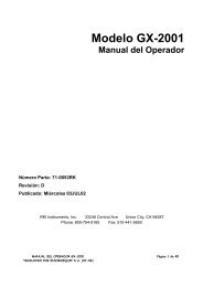
<strong>35</strong>-<strong>3000RK</strong>-<strong>LEL</strong><br />
<strong>Combustible</strong> <strong>Gas</strong> <strong>Sample</strong>-<strong>Draw</strong> Detector<br />
Operator’s Manual<br />
Part Number: 71-0104RK<br />
Revision: P1<br />
Released: 9/18/04<br />
<strong>RKI</strong> <strong>Instruments</strong> Inc.<br />
1855 Whipple Road<br />
Hayward, CA 94544<br />
PH: 800-754-5165 Fax: 510-441-5650<br />
www.rkiinstruments.com
Product Warranty<br />
<strong>RKI</strong> <strong>Instruments</strong>, Inc., warrants gas alarm equipment sold by us to be free from defects in<br />
materials, workmanship, and performance for a period of one year from date of shipment<br />
from <strong>RKI</strong> <strong>Instruments</strong>, Inc. Any parts found defective within that period will be repaired<br />
or replaced, at our option, free of charge. This warranty does not apply to those items<br />
which by their nature are subject to deterioration or consumption in normal service, and<br />
which must be cleaned, repaired, or replaced on a routine basis. Examples of such items<br />
are:<br />
a) Absorbent cartridges d) Batteries<br />
b) Pump diaphragms and valves e) Filter elements<br />
c) Fuses<br />
Warranty is voided by abuse including mechanical damage, alteration, rough handling, or<br />
repair procedures not in accordance with the operator’s manual. This warranty indicates<br />
the full extent of our liability, and we are not responsible for removal or replacement costs,<br />
local repair costs, transportation costs, or contingent expenses incurred without our prior<br />
approval.<br />
THIS WARRANTY IS EXPRESSLY IN LIEU OF ANY AND ALL OTHER<br />
WARRANTIES AND REPRESENTATIONS, EXPRESSED OR IMPLIED,<br />
AND ALL OTHER OBLIGATIONS OR LIABILITIES ON THE PART OF<br />
<strong>RKI</strong> INSTRUMENTS, INC., INCLUDING BUT NOT LIMITED TO, THE<br />
WARRANTY OF MERCHANTABILITY OR FITNESS FOR A<br />
PARTICULAR PURPOSE. IN NO EVENT SHALL <strong>RKI</strong> INSTRUMENTS,<br />
INC., BE LIABLE FOR INDIRECT, INCIDENTAL, OR CONSEQUENTIAL<br />
LOSS OR DAMAGE OF ANY KIND CONNECTED WITH THE USE OF<br />
ITS PRODUCTS OR FAILURE OF ITS PRODUCTS TO FUNCTION OR<br />
OPERATE PROPERLY.<br />
This warranty covers instruments and parts sold to users by authorized distributors,<br />
dealers, and representatives as appointed by <strong>RKI</strong> <strong>Instruments</strong>, Inc.<br />
We do not assume indemnification for any accident or damage caused by the operation of<br />
this gas monitor, and our warranty is limited to the replacement of parts or our complete<br />
goods.<br />
2 • <strong>35</strong>-<strong>3000RK</strong>-<strong>LEL</strong> <strong>Combustible</strong> <strong>Gas</strong> <strong>Sample</strong>-<strong>Draw</strong> Detector
Table of Contents<br />
Overview . . . . . . . . . . . . . . . . . . . . . . . . . . . . . . . . . . . . . . . . . . . . . . . . . . . . . . . . . . . . . . . . . . . 4<br />
Specifications . . . . . . . . . . . . . . . . . . . . . . . . . . . . . . . . . . . . . . . . . . . . . . . . . . . . . . . . . . . . . . . . 4<br />
Description. . . . . . . . . . . . . . . . . . . . . . . . . . . . . . . . . . . . . . . . . . . . . . . . . . . . . . . . . . . . . . . . . . 5<br />
Housing . . . . . . . . . . . . . . . . . . . . . . . . . . . . . . . . . . . . . . . . . . . . . . . . . . . . . . . . . . . . . . . . . . . . . . . . . . . . . 5<br />
Flow System. . . . . . . . . . . . . . . . . . . . . . . . . . . . . . . . . . . . . . . . . . . . . . . . . . . . . . . . . . . . . . . . . . . . . . . . . . 6<br />
Detection System. . . . . . . . . . . . . . . . . . . . . . . . . . . . . . . . . . . . . . . . . . . . . . . . . . . . . . . . . . . . . . . . . . . . . . 7<br />
Installation . . . . . . . . . . . . . . . . . . . . . . . . . . . . . . . . . . . . . . . . . . . . . . . . . . . . . . . . . . . . . . . . . . 9<br />
Mounting the <strong>Combustible</strong> <strong>Gas</strong> <strong>Sample</strong>-<strong>Draw</strong> Detector . . . . . . . . . . . . . . . . . . . . . . . . . . . . . . . . . . . . 9<br />
Connecting the <strong>Sample</strong> Lines to the <strong>Sample</strong>-<strong>Draw</strong> Detector . . . . . . . . . . . . . . . . . . . . . . . . . . . . . . . . 10<br />
Wiring the <strong>Combustible</strong> <strong>Gas</strong> <strong>Sample</strong>-<strong>Draw</strong> Detector to a Controller. . . . . . . . . . . . . . . . . . . . . . . . . 10<br />
Start Up . . . . . . . . . . . . . . . . . . . . . . . . . . . . . . . . . . . . . . . . . . . . . . . . . . . . . . . . . . . . . . . . . . . . 12<br />
Introducing Incoming Power . . . . . . . . . . . . . . . . . . . . . . . . . . . . . . . . . . . . . . . . . . . . . . . . . . . . . . . . . . 12<br />
Setting the Fresh Air Reading . . . . . . . . . . . . . . . . . . . . . . . . . . . . . . . . . . . . . . . . . . . . . . . . . . . . . . . . . . 12<br />
Maintenance. . . . . . . . . . . . . . . . . . . . . . . . . . . . . . . . . . . . . . . . . . . . . . . . . . . . . . . . . . . . . . . . 13<br />
Preventive Maintenance . . . . . . . . . . . . . . . . . . . . . . . . . . . . . . . . . . . . . . . . . . . . . . . . . . . . . . . . . . . . . . 13<br />
Troubleshooting . . . . . . . . . . . . . . . . . . . . . . . . . . . . . . . . . . . . . . . . . . . . . . . . . . . . . . . . . . . . . . . . . . . . . 14<br />
Replacing Components of the <strong>Combustible</strong> <strong>Gas</strong> <strong>Sample</strong>-<strong>Draw</strong> Detector . . . . . . . . . . . . . . . . . . . . . 16<br />
Adjusting the Low Flow Setting. . . . . . . . . . . . . . . . . . . . . . . . . . . . . . . . . . . . . . . . . . . . . . . . . . . . . . . . 17<br />
Calibration . . . . . . . . . . . . . . . . . . . . . . . . . . . . . . . . . . . . . . . . . . . . . . . . . . . . . . . . . . . . . . . . . 18<br />
Assembling the Calibration Kit . . . . . . . . . . . . . . . . . . . . . . . . . . . . . . . . . . . . . . . . . . . . . . . . . . . . . . . . 18<br />
Setting the Fresh Air Reading . . . . . . . . . . . . . . . . . . . . . . . . . . . . . . . . . . . . . . . . . . . . . . . . . . . . . . . . . . 19<br />
Setting the Zero Reading . . . . . . . . . . . . . . . . . . . . . . . . . . . . . . . . . . . . . . . . . . . . . . . . . . . . . . . . . . . . . . 19<br />
Parts List . . . . . . . . . . . . . . . . . . . . . . . . . . . . . . . . . . . . . . . . . . . . . . . . . . . . . . . . . . . . . . . . . . . 20<br />
<strong>35</strong>-<strong>3000RK</strong>-<strong>LEL</strong> Combustilbe <strong>Gas</strong> <strong>Sample</strong>-<strong>Draw</strong> Detector • 3
Overview<br />
This operator’s manual describes the combustible gas sample-draw detector. This manual<br />
also describes how to install, start up, maintain, and calibrate the sample-draw detector<br />
when using it with a gas monitoring controller. A parts list at the end of this manual lists<br />
replacement parts and accessories for the sample-draw detector.<br />
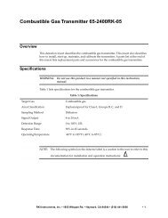
Specifications<br />
Table 1 lists specifications for the combustible gas sample-draw detector. See the controller<br />
Operator’s Manual for information specific to the controller.<br />
Table 1: Specifications<br />
Target <strong>Gas</strong><br />
Input Power<br />
<strong>Combustible</strong> gas, methane calibration standard<br />
24 VDC Nominal (23 VDC - 28 VDC)<br />
Construction (housing) Fiberglass/polyester (NEMA 4X)<br />
Dimensions<br />
Weight<br />
Sampling Method<br />
<strong>Sample</strong> Flow<br />
8.5 in. H x 6.5 in. W x 4.25 in. D<br />
4.5 lbs.<br />
<strong>Sample</strong>-draw<br />
1.5 SCFH (nominal)<br />
Detection Range 0 to 100% <strong>LEL</strong> 1<br />
Response Time<br />
Linearity<br />
Repeatability<br />
90% in 30 seconds<br />
±5% of detection range<br />
±2% of detection range<br />
4 • <strong>35</strong>-<strong>3000RK</strong>-<strong>LEL</strong> <strong>Combustible</strong> <strong>Gas</strong> <strong>Sample</strong>-<strong>Draw</strong> Detector
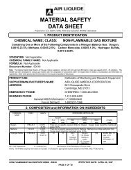
Description<br />
This section describes the components of the combustible gas sample-draw detector. The<br />
sample-draw detector consists of the housing, flow system, and detection system.<br />
Flow Adjust<br />
Potentiometer<br />
Mounting<br />
Foot, 4X<br />
Low Flow Potentiometer<br />
Pump/Pressure Switch<br />
Terminal Block<br />
Fail LED<br />
Detector<br />
Terminal Strip<br />
Pilot LED<br />
Flowmeter<br />
Bypass valve<br />
Hydrophobic<br />
Filter<br />
Exhaust<br />
Fitting<br />
Inlet<br />
Fitting<br />
Relay<br />
Interconnect<br />
Terminal Strip<br />
Oxygen Detector<br />
(Not Used in This<br />
Version)<br />
<strong>Combustible</strong><strong>Gas</strong><br />
Detector<br />
3/4" Conduit Hub, 2X<br />
Figure 1: <strong>Combustible</strong> <strong>Gas</strong> Detector <strong>Sample</strong>-draw Component Location<br />
Housing<br />
The sample-draw detector’s fiberglass housing is weather- and corrosion-resistant. It is<br />
suitable for installation where general purpose equipment is in use.<br />
The housing door is hinged on the left side and is secured by two latches on the right side.<br />
The flowmeter and status lights are visible through a window in the housing door.<br />
Four mounting feet are attached to the back of the housing (one at each corner). Use the<br />
mounting feet to install the housing to a vertical surface. Use the two conduit hubs on the<br />
bottom of the housing to make wiring connections to a gas monitoring controller.<br />
An aluminum subpanel is mounted to the interior of the housing. The sample-draw<br />
detector’s internal components are mounted to the subpanel.<br />
<strong>35</strong>-<strong>3000RK</strong>-<strong>LEL</strong> Combustilbe <strong>Gas</strong> <strong>Sample</strong>-<strong>Draw</strong> Detector • 5
Flow System<br />
The sample-draw detector’s flow system consists of the INLET fitting, hydrophobic filter,<br />
pump, flowmeter, bypass valve, status lights, pressure switch, and EXHAUST fitting (see<br />
Figure 1). Figure 2 illustrates how the gas sample moves through the flow system.<br />
Bypass<br />
Valve<br />
To<br />
Exhaust<br />
Inlet Filter Pump Sensor<br />
Flowmeter<br />
Pressure Switch<br />
Figure 2: <strong>Combustible</strong> <strong>Gas</strong> <strong>Sample</strong>-draw Detector Flow Diagram<br />
INLET fitting<br />
The INLET fitting on the right side of the housing allows the gas sample to enter the<br />
sample-draw detector. The INLET fitting accepts 1/4 in. rigid tubing. See the Installation<br />
section on page 9 to connect tubing to the INLET fitting.<br />
Hydrophobic Filter<br />
The hydrophobic filter is below the main circuit board. The filter prevents particulates and<br />
water in the incoming gas sample from damaging the flow and detection systems. Replace<br />
the filter when it appears dirty, discolored, or clogged.<br />
Pump<br />
The pump is behind the main circuit board near the top of the sample-draw detector.<br />
The pump pulls the gas sample into the sample-draw detector. The pump operates on<br />
24 VAC, which is generated from the 24 VDC supplied by the controller.<br />
Flowmeter<br />
The flowmeter is attached to the main circuit board near the top left corner (see Figure 1.)<br />
You can see it through the window in the door. A ball in the flowmeter column indicates<br />
the flow rate of the sample-draw detector. The flowmeter measures the flow in the range<br />
0.2 to 2.0 SCFH (Standard Cubic Feet per Hour). The optimum flow rate is 1.5 SCFH.<br />
Bypass valve<br />
The bypass valve is to the left of the flowmeter. The bypass valve adjusts the flow rate to<br />
the detector. Use a flat-blade screwdriver to adjust the bypass valve.<br />
NOTE:<br />
The bypass valve allows fine adjustments of the flow rate. For a wider range of<br />
adjustment, use the flow adjust potentiometer (see Figure 1.)<br />
6 • <strong>35</strong>-<strong>3000RK</strong>-<strong>LEL</strong> <strong>Combustible</strong> <strong>Gas</strong> <strong>Sample</strong>-<strong>Draw</strong> Detector
Status lights<br />
Two status lights are above the flowmeter. They are also visible through the window in<br />
the housing door.<br />
Pilot light<br />
The green Pilot light is on when the sample-draw detector is receiving power from the<br />
controller.<br />
Fail light<br />
The red Fail light is on when the sample flow rate is below the low flow level.<br />
NOTE:<br />
The factory set low flow level is 0.6 SCFH (±0.2). See “Adjusting the Low Flow<br />
Setting” on page 17 to adjust this setting.<br />
Pressure switch<br />
The pressure switch is mounted to the opposite side of the main circuit board. The<br />
pressure switch monitors the flow rate of the incoming gas sample.<br />
If the flow rate falls below the preset low flow level, the pressure switch causes the fail<br />
relay to interrupt the signal from the detector. The interrupted detector signal causes a fail<br />
condition at the controller. The low flow level is factory-set at 0.6 SCFH (±0.2 SCFH).<br />
EXHAUST fitting<br />
The EXHAUST fitting on the right side of the housing allows the gas sample to exit the<br />
sample-draw detector. The EXHAUST fitting accepts 1/4 in. rigid tubing. See the<br />
Installation section on page 9 to connect tubing to the EXHAUST fitting.<br />
Detection System<br />
The detection system consists of the combustible gas sensor and the main circuit board.<br />
<strong>Combustible</strong> <strong>Gas</strong> sensor<br />
The combustible gas sensor is installed in a cavity block. The cavity block is mounted to<br />
the aluminum subpanel near the bottom of the sample-draw detector. The combustible<br />
gas sensor includes the sensing elements, flame arrestor, connector, and sensor leads.<br />
NOTE:<br />
The cavity block includes a cavity for an oxygen sensor. This version of the<br />
sample-draw detector does not include the oxygen sensor.<br />
Sensing elements<br />
Two sensing elements are protected within the sensor assembly. Through a series of<br />
thermal and electronic reactions, these elements produce an electrical output that is<br />
proportional to the detection range of the sample-draw detector.<br />
Flame arrestor<br />
The porous flame arrestor allows the gas sample to enter the sensor assembly and contact<br />
the sensing elements. The flame arrestor also contains any sparks that may occur within<br />
the sensor.<br />
Connector<br />
The top of the sensor includes five pins that plug into the socket connector. This connector<br />
allows you to replace the sensor without disconnecting the wiring. The sensor leads are<br />
soldered to the connector.<br />
<strong>35</strong>-<strong>3000RK</strong>-<strong>LEL</strong> Combustilbe <strong>Gas</strong> <strong>Sample</strong>-<strong>Draw</strong> Detector • 7
Sensor leads<br />
Four color-coded leads extend from the connector. The leads allow you to connect the<br />
combustible gas sensor to the main circuit board.<br />
Main Circuit Board<br />
The main circuit board includes the interconnect terminal strip, detector terminal strip,<br />
pump terminal strip, and relay (see Figure 1).<br />
NOTE:<br />
The flowmeter and status lights are mounted to the main circuit board but are<br />
considered part of the flow system.<br />
Interconnect terminal strip<br />
The interconnect terminal strip is the nine-point terminal strip near the bottom edge of the<br />
main circuit board. Use the interconnect terminal strip to connect the sample-draw<br />
detector to a controller<br />
Detector terminal strip<br />
The detector terminal strip is the nine-point terminal strip near the right edge of the circuit<br />
board. Use the detector terminal strip to connect the combustible gas sensor to the main<br />
circuit board.<br />
NOTE:<br />
The combustible gas sensor is factory-wired to the circuit board. See the<br />
“Installation” section on page 9 for all wiring procedures related to the sampledraw<br />
detector.<br />
Pump terminal strip<br />
The pump terminal strip is the four-point terminal strip near the top edge of the circuit<br />
board. Use the pump terminal strip to connect the pump and pressure switch to the main<br />
circuit board.<br />
NOTE:<br />
The pump and pressure switch are factory-wired to the circuit board. See the<br />
“Installation” on page 9 for all wiring procedures related to the sample-draw<br />
detector.<br />
Relay<br />
The relay is to the left of the detector terminal strip. The relay is single-pole, double-throw<br />
(SPDT) and is rated for 2 amps at 25 VDC (resistive). If the pressure switch senses a low<br />
flow condition, the relay interrupts the signal from the sensor. The interrupted sensor<br />
signal causes a fail condition at the controller<br />
8 • <strong>35</strong>-<strong>3000RK</strong>-<strong>LEL</strong> <strong>Combustible</strong> <strong>Gas</strong> <strong>Sample</strong>-<strong>Draw</strong> Detector
Installation<br />
This section describes procedures to mount the sample-draw detector in the monitoring<br />
environment and wire the sample-draw detector to a controller.<br />
Mounting the <strong>Sample</strong>-<strong>Draw</strong> <strong>Combustible</strong> <strong>Gas</strong> Detector<br />
1. Select the mounting site. Consider the following when you select the mounting site.<br />
• Is there enough room to open the housing door and make wiring connections at<br />
the bottom of the housing and tubing connections at the right of the housing?<br />
Make sure there is sufficient room to perform start-up, maintenance, and<br />
calibration procedures.<br />
• Are the flowmeter and status lights visible?<br />
7.3 in.<br />
4.0 in.<br />
6.5 in.<br />
8.5<br />
in.<br />
8.9<br />
in.<br />
9.3<br />
in.<br />
Note: The housing is 4.25 in. deep.<br />
3/4 in. conduit hub<br />
(total of 2 hubs)<br />
Figure 3: Mounting the <strong>Combustible</strong> <strong>Gas</strong> <strong>Sample</strong>-<strong>Draw</strong> Detector<br />
4. Close and latch the housing door.<br />
<strong>35</strong>-<strong>3000RK</strong>-<strong>LEL</strong> Combustilbe <strong>Gas</strong> <strong>Sample</strong>-<strong>Draw</strong> Detector • 9
NOTE:<br />
The sample-draw detector is shipped with the mounting feet “tucked under” the<br />
housing to protect the mounting feet during shipment.<br />
5. Slightly loosen the screw that secures the mounting foot to the housing, then rotate<br />
the mounting foot 180 degrees (see Figure 3).<br />
6. Tighten the screw that secures the mounting foot to the housing.<br />
7. Repeat steps 3 and 4 for the remaining three mounting feet.<br />
8. Position the sample-draw housing on a vertical surface at eye level (4 1/2 to 5 feet<br />
from the floor).<br />
9. Insert 1/4 inch or 5/16 inch screws through the slots in the mounting feet to secure<br />
the housing to the mounting surface.<br />
Connecting the <strong>Sample</strong> Lines to the <strong>Sample</strong>-<strong>Draw</strong> Detector<br />
1. Attach 1/4 in. metal or rigid plastic sample tubing to the INLET fitting. Brass tubing is<br />
recommended for most applications. If tubing corrosion caused by the air being<br />
sampled is a concern, stainless steel tubing or rigid polypropylene tubing may be<br />
used.<br />
CAUTION: If you use flexible sample tubing (polyurethane for example), use an appropriate<br />
metal insert to seal the connection between the tubing and the INLET fitting. See the<br />
Parts List at the end of this manual, for an example of an appropriate metal insert.<br />
2. Place the opposite end of the tubing at the sampling area.<br />
CAUTION: Avoid loops or slumps in the incoming sample line. To reduce response time, keep the<br />
incoming sample line as short as possible.<br />
3. Attach rigid sample tubing to the EXHAUST fitting.<br />
4. Route the opposite end of the tubing to an open area where the sample can safely<br />
disperse.<br />
Wiring the <strong>Sample</strong>-<strong>Draw</strong> <strong>Combustible</strong> <strong>Gas</strong> Detector to a Controller<br />
WARNING:<br />
Always verify that the controller is off and that power to the controller is<br />
off before you make wiring connections.<br />
1. Turn off the controller<br />
2. Turn off power to the controller.<br />
3. Unlatch and open the housing door of the sample-draw detector.<br />
4. Guide a six-conductor, shielded cable or six wires in conduit through one of the<br />
conduit hubs at the bottom of the sample-draw housing.<br />
5. Connect the cable to the sample-draw detector’s interconnect terminal strip as shown<br />
in Figure 4.<br />
6. Close and latch the housing door of the sample-draw detector.<br />
10 • <strong>35</strong>-<strong>3000RK</strong>-<strong>LEL</strong> <strong>Combustible</strong> <strong>Gas</strong> <strong>Sample</strong>-<strong>Draw</strong> Detector
CAUTION: If using shielded cable, leave the cable shield’s drain wire insulated and disconnected<br />
at the sample-draw detector. You will connect the opposite end of the drain wire at<br />
the controller.<br />
7. Route the cable or wires in conduit leading from the sample-draw detector through<br />
one of the conduit hubs at the controller.<br />
CAUTION: Do not route controller power wiring and detector wiring through the same hub.<br />
The power cable may disrupt the transmission of the sensor signal to the controller.<br />
8. Connect the wires to the applicable detector terminal strip and power terminals at the<br />
controller as shown in Figure 4.<br />
<strong>LEL</strong> <strong>Sample</strong>-<strong>Draw</strong>Detector Housing<br />
Pump.,<br />
Internally Wired<br />
PUMP<br />
PSW<br />
Pressure Switch,<br />
Internally Wired<br />
<strong>Sample</strong>-<strong>Draw</strong> Detector<br />
Main Circuit Board<br />
H N GND RD WHT GRN BLK GND 24V 4/20<br />
115VAC<br />
<strong>LEL</strong>/ O2<br />
AMP<br />
+ _<br />
P- AMP<br />
Black<br />
Green<br />
White<br />
Red<br />
ACTerminal<br />
Strip Not Used<br />
On This<br />
Version<br />
<strong>Combustible</strong><br />
<strong>Gas</strong> Sensor,<br />
Internally Wired<br />
Controller <strong>LEL</strong><br />
Sensor Terminals<br />
Red<br />
White<br />
Green<br />
Black<br />
Controller Terminals<br />
- (DC -)<br />
+24VDC<br />
Figure 4: Wiring the <strong>Sample</strong>-<strong>Draw</strong> Detector to a Controller<br />
<strong>35</strong>-<strong>3000RK</strong>-<strong>LEL</strong> Combustilbe <strong>Gas</strong> <strong>Sample</strong>-<strong>Draw</strong> Detector • 11
5. Connect the cable shield to an available chassis ground at the controller. The<br />
grounding screw on one of the controller’s grounded conduit hubs is an example of a<br />
chassis ground.<br />
Start Up<br />
This section describes procedures to start up the sample-draw detector and place the<br />
sample-draw detector into normal operation.<br />
Introducing Incoming Power<br />
1. Complete the installation procedures described earlier in this manual.<br />
2. Verify that the wiring is correct and secure. Refer to the controller operator’s manual<br />
for connections at the controller.<br />
3. Turn on or plug in the power to the controller, then turn on the controller.<br />
4. Verify that the sample-draw detector’s PILOT light is on.<br />
5. Verify that the controller is on and operating properly. Refer to the controller<br />
operator’s manual.<br />
6. Verify that the flowmeter indicates a flow rate of approximately 1.5 SCFH. If<br />
necessary, use the bypass valve or flow adjust potentiometer to adjust the flow rate.<br />
NOTE:<br />
The following step tests for leaks in the sample line. This test will cause a low<br />
flow condition at the sample-draw detector and a fail condition at the controller.<br />
Be sure to put the controller into its calibration program or disable external<br />
alarms before performing this test.<br />
7. Verify that the incoming sample line is not leaking. To test the sample line, plug the<br />
open end of the sample line with your thumb. If the flowmeter ball drops to the<br />
bottom of the flowmeter, the incoming sample line is not leaking.<br />
8. Remove your thumb from the sample line, verify that the flowmeter returns to a<br />
normal flow rate.<br />
9. Enable alarms or place the controller in normal operation.<br />
CAUTION: Allow the sample-draw detector to warm up for 15 minutes before you continue with<br />
the next section, “Setting the Zero Reading.”<br />
Setting the Zero Reading<br />
CAUTION: If you suspect the presence of combustible gas in the monitoring environment, use<br />
the calibration kit and the zero air calibration cylinder to introduce “fresh air” to the<br />
sensor and verify an accurate zero setting. See “Calibration” on page 18 for<br />
instructions on using a zero air calibration cylinder for setting the zero reading.<br />
1. Verify that the sample-draw detector is sampling a fresh air environment<br />
(environment known to be free of combustible gas).<br />
2. Verify a reading of 0 %<strong>LEL</strong> on the controller display screen for the applicable channel.<br />
If the display reading is 0 % <strong>LEL</strong>, start up is complete. The sample-draw detector is in<br />
normal operation. If the display reading is not 0 % <strong>LEL</strong>, continue with step 3.<br />
12 • <strong>35</strong>-<strong>3000RK</strong>-<strong>LEL</strong> <strong>Combustible</strong> <strong>Gas</strong> <strong>Sample</strong>-<strong>Draw</strong> Detector
3. Perform a zero operation at the controller. See the controller operator’s manual for<br />
instructions to perform a zero operation.<br />
Maintenance<br />
This section describes maintenance procedures. It includes preventive maintenance<br />
procedures. This section also includes procedures to troubleshoot the sample-draw<br />
detector, replace components of the sample-draw detector, and adjust the low flow<br />
setting.<br />
Preventive Maintenance<br />
This section describes a preventive maintenance schedule to ensure the optimum<br />
performance of the sample-draw detector. It includes daily, monthly, and quarterly<br />
procedures.<br />
Monthly Visual Checks<br />
1. Verify that the pilot light is on.<br />
2. Verify that the flowmeter indicates a flow rate of approximately 1.5 SCFH.<br />
If necessary use the bypass valve or flow adjust potentiometer to adjust the flow rate<br />
to 1.5 SCFH.<br />
3. Verify a display reading of 0 %<strong>LEL</strong> at the controller. Investigate significant changes in<br />
the display reading.<br />
Monthly Response Test<br />
This procedure describes a test to verify that the sample-draw detector responds properly<br />
to the target gas.<br />
NOTE:<br />
To reduce the response time of this test, use a short incoming sample line. If the<br />
sample-draw detector’s sample line is long, connect a shorter line for this test.<br />
Make sure you reconnect the sample line after you complete this procedure.<br />
NOTE:<br />
Performing a response test on the sample-draw detector may cause alarms. Be<br />
sure to put the controller into its calibration program or disable external alarms<br />
before performing this test<br />
Preparing for the response test<br />
NOTE:<br />
This procedure describes the <strong>RKI</strong> calibration kit that includes a dispensing valve<br />
and a gas collection bag. A calibration kit that uses a demand flow regulator is<br />
also available.<br />
1. Verify that the display reading a the controller is 0 % <strong>LEL</strong>.<br />
If the display reading is not 0 % <strong>LEL</strong>, set the zero reading as described in<br />
“Calibration” on page 18, then continue this procedure.<br />
1. Follow the instructions in the controller’s operator’s manual for entering calibration<br />
mode.<br />
2. Connect the calibration kit sample tubing to the fitting on the gas collection bag and<br />
run the tubing through the tubing clamp provided with the calibration kit.<br />
<strong>35</strong>-<strong>3000RK</strong>-<strong>LEL</strong> Combustilbe <strong>Gas</strong> <strong>Sample</strong>-<strong>Draw</strong> Detector • 13
3. Disconnect the incoming sample line from the sample-draw detector’s inlet fitting,<br />
then connect the sample tubing from the gas collection bag to the inlet fitting.<br />
Allow the sample-draw pump to draw out any residual gas in the gas collection bag.<br />
4. Close the tubing clamp.<br />
NOTE:<br />
This step will cause a low flow alarm.<br />
5. Disconnect the calibration kit sample tubing from the inlet fitting.<br />
NOTE:<br />
If you can verify a fresh air environment, it is not necessary to use a zero air<br />
calibrating sample to set the zero reading at the controller. If you can verify a<br />
fresh air environment, go to the next section, Setting the Zero Reading.<br />
6. Screw the dispensing valve onto the test gas cylinder.<br />
7. Connect the tubing from the gas collection bag to the dispensing valve, then open the<br />
clamp.<br />
8. Open the dispensing valve. The gas collection bag begins to fill.<br />
9. Close the dispensing valve when the gas collection bag appears full.<br />
10. Close the tubing clamp, then disconnect the sample tubing from the dispensing valve.<br />
11. Remove the dispensing valve from the test gas cylinder.<br />
Performing the response test<br />
1. Connect the calibration tubing from the gas collection bag to the INLET fitting.<br />
The sample-draw detector’s pump automatically begins pulling the test sample from<br />
the gas collection bag when you connect the tubing to the INLET fitting.<br />
2. After approximately one minute, verify that the reading at the controller stabilizes<br />
within ± 10% of the concentration of the test sample. If the reading is not within ± 10%<br />
of the test sample, calibrate the sample-draw detector as described in “Calibration” on<br />
page 18.<br />
3. Remove the calibration tubing from the INLET fitting, then reconnect the sample<br />
tubing to the INLET fitting.<br />
Quarterly Calibration<br />
<strong>RKI</strong> <strong>Instruments</strong> recommends calibrating the combustible gas sample-draw detector<br />
quarterly. Some applications may require a more or less frequent calibration schedule<br />
depending on environmental conditions, frequency of gas exposure, and other factors.<br />
Calibrate the sample-draw detector as described in “Calibration” on page 18.<br />
Troubleshooting<br />
The troubleshooting guide describes symptoms, probable causes, and recommended<br />
action for problems you may encounter with the sample-draw detector.<br />
NOTE:<br />
This troubleshooting guide describes sample-draw detector problems only. See<br />
the controller Operator’s Manual if the controller exhibits any problems.<br />
14 • <strong>35</strong>-<strong>3000RK</strong>-<strong>LEL</strong> <strong>Combustible</strong> <strong>Gas</strong> <strong>Sample</strong>-<strong>Draw</strong> Detector
Fail condition<br />
Symptoms<br />
• The sample-draw detector’s Fail light is on.<br />
• The monitoring device is operating properly but indicates a reading well below zero.<br />
Probable causes<br />
• The sample-draw detector’s flow rate is too low because of an obstructed sample line,<br />
failed pump, etc.<br />
• The sample-draw detector is malfunctioning.<br />
• The sensor wiring is disconnected or misconnected.<br />
Recommended action<br />
1. At the sample-draw detector, set the correct flow rate with the bypass valve or flow<br />
adjust potentiometer.<br />
2. If you cannot set the correct flow rate, check the sample lines for obstructions or kinks.<br />
3. Verify that the sensor wiring is correct and secure. “Wiring the <strong>Sample</strong>-<strong>Draw</strong><br />
<strong>Combustible</strong> <strong>Gas</strong> Detector to a Controller” on page 10 describes sensor wiring<br />
connections.<br />
4. Calibrate the sample-draw detector as described in “Calibration” on page 18.<br />
5. If the fail condition continues, replace the sensor as described later in this section.<br />
6. If the fail condition continues, contact <strong>RKI</strong> <strong>Instruments</strong>, Inc., for further instruction.<br />
Slow or no response/difficult or unable to calibrate<br />
Symptoms<br />
• The sensor responds slowly or does not respond during the monthly response test.<br />
• Unable to accurately set the zero or response reading during the calibration<br />
procedure.<br />
• The sensor requires frequent calibration.<br />
Probable causes<br />
• The calibration cylinder is low, out-dated, or defective.<br />
• If a demand flow regulator calibration kit is used, the demand flow regulator is not<br />
functioning properly.<br />
• The sample-draw detector’s flow rate is too low because of an obstructed sample line,<br />
failed pump, etc.<br />
• The sample-draw detector is malfunctioning.<br />
Recommended action<br />
1. Verify that the calibration cylinder contains an adequate supply of a fresh test sample.<br />
2. If a demand flow regulator calibration kit is used, use a different demand flow<br />
regulator to determine if the original one if functioning properly.<br />
3. If necessary, set the correct flow rate with the bypass valve or flow adjust<br />
potentiometer.<br />
4. If you cannot set the correct flow rate, check the sample line for obstructions or kinks.<br />
5. If the calibration/response difficulties continue, replace the sensor as described later<br />
in this section.<br />
<strong>35</strong>-<strong>3000RK</strong>-<strong>LEL</strong> Combustilbe <strong>Gas</strong> <strong>Sample</strong>-<strong>Draw</strong> Detector • 15
6. If the calibration/response difficulties continue, contact <strong>RKI</strong> <strong>Instruments</strong>, Inc., for<br />
further instruction.<br />
Replacing Components of the <strong>Combustible</strong> <strong>Gas</strong><br />
<strong>Sample</strong>-draw Detector<br />
This section includes procedures to replace the sensor, hydrophobic filter, and ferrules.<br />
Replacing the combustible gas sensor<br />
1. Turn off the controller<br />
2. Turn off power to the controller.<br />
3. Open the housing door of the sample-draw detector.<br />
4. Unscrew and remove the two screws that secure the sensor retraining plate, then lift<br />
the plate, connector, and sensor out of the housing.<br />
5. Unplug the connector from the sensor.<br />
6. Verify that you are using the correct replacement sensor (NC-6240 is printed on the<br />
sensor), then plug the sensor into the connector.<br />
7. Place the sensor in the combustible gas sensor cavity, then position the retaining plate<br />
on the two standoffs.<br />
8. Secure the retaining plate to the standoffs with the two screws you removed in step 4.<br />
9. Close and latch the housing door.<br />
10. Turn on power to the controller.<br />
11. Turn on the controller.<br />
CAUTION: Allow the replacement sensor to warm up for 15 minutes before you continue.<br />
12. Calibrate the replacement sensor as described in “Calibration” on page 18.<br />
Replacing the filter<br />
1. Open the housing door of the sample-draw detector.<br />
2. Disconnect the filter from the rubber elbows on each end of the filter, then remove the<br />
filter from the sample-draw detector.<br />
3. Install the new filter.<br />
4. Verify that the flow rate is approximately 1.5 SCFH, then close the housing door.<br />
Replacing the ferrules<br />
The INLET and EXHAUST fittings each includes two ferrules that seal the inlet or exhaust<br />
tubing to the fitting. Replace the ferrules if the seal is bad or if you replace the sample<br />
tubing. Always replace the ferrules as a pair.<br />
1. Unscrew the nut that holds the tubing to the fitting from the fitting.<br />
2. Slide the nut away from the end of the tubing.<br />
3. Cut off the end of the sample tube with the old ferrules off about one inch from the<br />
end<br />
4. Slide the nut off the sample tubing.<br />
5. Position the nut so the threaded end is facing you, then insert the bottom (smaller)<br />
ferrule into the nut. Insert the ferrule so the flat side is facing down.<br />
16 • <strong>35</strong>-<strong>3000RK</strong>-<strong>LEL</strong> <strong>Combustible</strong> <strong>Gas</strong> <strong>Sample</strong>-<strong>Draw</strong> Detector
NOTE:<br />
Make sure the bottom ferrule is laying flat in the nut.<br />
6. Insert the cone-shaped front ferrule on top of the bottom ferrule. Insert the ferrule so<br />
the smaller end of the cone is facing up.<br />
7. Screw the nut onto the fitting by hand just until it stops turning.<br />
8. Insert the sample tubing into the fitting until it bottoms out.<br />
9. Firmly tighten the nut so the ferrules crimp onto the sample tubing and make a seal.<br />
Adjusting the Low Flow Setting<br />
NOTE:<br />
Adjusting the low flow setting will cause a low flow alarm at the sample-draw<br />
detector and a fail alarm at the controller. Be sure to put the controller into its<br />
calibration program or disable external alarms before performing this test<br />
The factory-set low flow setting is 0.6 SCFH (±0.2). To adjust the low flow setting:<br />
1. Use the flow adjust potentiometer (VR1) to set the flow to 0.6 SCFH.<br />
If the sample-draw detector goes into low flow alarm before you can adjust the flow<br />
down to 0.6 SCFH, adjust the low flow potentiometer 1/4 turn clockwise, then<br />
attempt to set the flow again. Repeat this step until you are able to adjust the flow to<br />
0.6 SCFH.<br />
NOTE:<br />
The low flow potentiometer is accessible through a circular cutout in the main<br />
circuit board. The cutout is labeled PS1.<br />
2. Slowly turn the low flow potentiometer counterclockwise just until the sample-draw<br />
detector goes into low flow alarm.<br />
3. Increase the flow using VR1 until the unit is out of low flow alarm.<br />
4. Decrease the flow very slowly and verify that the low flow alarm is 0.6 SCFH (±0.2).<br />
If the low flow alarm is set too low, turn the low flow potentiometer slightly<br />
clockwise. Repeat steps 3 and 4 if necessary.<br />
5. Use the flow adjust potentiometer (VR1) to set the flow to 1.5 SCFH.<br />
6. Make sure the sample-draw detector’s Fail light is off.<br />
<strong>35</strong>-<strong>3000RK</strong>-<strong>LEL</strong> Combustilbe <strong>Gas</strong> <strong>Sample</strong>-<strong>Draw</strong> Detector • 17
Calibration<br />
This section describes how to calibrate the combustible gas sample-draw detector. It<br />
includes procedures to assemble the calibration kit, set the zero reading, set the response<br />
reading, and return to normal operation.<br />
The standard calibration gas for the sample-draw detector is methane. The sample-draw<br />
detector may be calibrated to other combustible gases such as hexane or hydrogen. Use<br />
the correct calibration gas for your installation.<br />
NOTE:<br />
Calibrating the sample-draw detector may cause alarms. Be sure to put the<br />
controller into its calibration program or disable external alarms before<br />
continuing.<br />
NOTE:<br />
This procedure describes calibration using a dispensing valve and a gas<br />
collection bag. A demand-flow regulator calibration kit is also available for<br />
calibrating the sample-draw detector without using a sample bag.<br />
Preparing for Calibration<br />
1. Follow the instructions in the controller’s operator’s manual for entering calibration<br />
mode.<br />
2. Connect the calibration kit sample tubing to the fitting on the gas collection bag and<br />
run the tubing through the tubing clamp provided with the calibration kit.<br />
3. Disconnect the incoming sample line from the sample-draw detector’s inlet fitting,<br />
then connect the sample tubing from the gas collection bag to the inlet fitting.<br />
Allow the sample-draw pump to draw out any residual gas in the gas collection bag.<br />
4. Close the tubing clamp.<br />
NOTE:<br />
This step will cause a low flow alarm.<br />
5. Disconnect the calibration kit sample tubing from the inlet fitting.<br />
NOTE:<br />
If you can verify a fresh air environment, it is not necessary to use a zero air<br />
calibrating sample to set the zero reading at the controller. If you can verify a<br />
fresh air environment, go to the next section, Setting the Zero Reading.<br />
6. Screw the dispensing valve onto the zero air calibration cylinder.<br />
7. Connect the tubing from the gas collection bag to the dispensing valve, then open the<br />
clamp.<br />
8. Open the dispensing valve. The gas collection bag begins to fill.<br />
9. Close the dispensing valve when the gas collection bag appears full.<br />
10. Close the tubing clamp, then disconnect the sample tubing from the dispensing valve.<br />
11. Remove the dispensing valve from the zero air calibration cylinder.<br />
18 • <strong>35</strong>-<strong>3000RK</strong>-<strong>LEL</strong> <strong>Combustible</strong> <strong>Gas</strong> <strong>Sample</strong>-<strong>Draw</strong> Detector
Setting the Zero Reading<br />
1. Open the tubing clamp, then connect the sample tubing from the gas collection bag to<br />
the sample-draw detector’s inlet line. This step is not necessary if you verified a<br />
fresh air environment earlier in this procedure.<br />
2. Allow the sample-draw detector to draw sample for one minute.<br />
3. Follow the directions in the controller’s operator’s manual for setting the zero<br />
reading. If you used a zero air calibration cylinder to set the zero reading, proceed to<br />
step 4. If you verified a fresh air environment, proceed to the next section, Setting the<br />
Response Reading.<br />
4. Allow the sample-draw detector to draw out any residual gas in the gas collection<br />
bag.<br />
5. Close the tubing clamp, then disconnect the gas bag sample tubing from the inlet<br />
fitting.<br />
NOTE:<br />
This step will cause a low flow alarm.<br />
6. Unscrew the dispensing valve from the zero air calibration cylinder.<br />
Setting the Span<br />
1. Screw the dispensing valve onto the combustible gas calibration cylinder.<br />
2. Connect the tubing from the gas collection bag to the dispensing valve, then open the<br />
clamp.<br />
3. Open the dispensing valve. The gas collection bag begins to fill.<br />
4. Close the dispensing valve when the gas collection bag appears full.<br />
5. Close the tubing clamp, then disconnect the sample tubing from the dispensing valve.<br />
6. Remove the dispensing valve from the combustible gas calibration cylinder.<br />
7. Open the tubing clamp, then connect the sample tubing from the gas collection bag to<br />
the sample-draw detector’s inlet line.<br />
8. Allow the sample-draw detector to draw sample for one minute.<br />
9. Follow the directions in the controller’s operator’s manual for setting the span.<br />
10. Allow the sample-draw detector to draw out any residual gas in the gas collection<br />
bag.<br />
NOTE:<br />
This step may cause a low flow alarm.<br />
11. Disconnect the gas bag sample tubing from the inlet fitting.<br />
12. Unscrew the dispensing valve from the combustible gas calibration cylinder.<br />
Returning to Normal Operation<br />
1. Wait approximately one minute to allow the combustible gas reading to decrease<br />
below the alarm level.<br />
2. Follow the instructions in the controller’s operator’s manual to exit the calibration<br />
mode.<br />
<strong>35</strong>-<strong>3000RK</strong>-<strong>LEL</strong> Combustilbe <strong>Gas</strong> <strong>Sample</strong>-<strong>Draw</strong> Detector • 19
Parts List<br />
Table 2 lists replacement parts and accessories for the sample-draw combustible gas<br />
detector.<br />
Table 2: Parts List<br />
Part Number<br />
06-1248RK<br />
17-2593RK<br />
17-2683RK<br />
17-2688RK<br />
30-0610RK<br />
33-0165RK<br />
61-0145RK<br />
71-0104RK<br />
81-0002RK-01<br />
81-0002RK-03<br />
81-0007RK-01<br />
81-0012RK-01<br />
81-0012RK-03<br />
81-0076RK-01<br />
81-0076RK-03<br />
81-1001RK<br />
81-1054RK<br />
81-1126RK<br />
Description<br />
<strong>Sample</strong> tubing, 3/16 x 5/16, specify length, (for calibration kit)<br />
Brass insert for flexible 1/4 OD x .17 ID tubing (for INLET and<br />
EXHAUST fittings)<br />
Front ferrule (for INLET and EXHAUST fittings)<br />
Back ferrule (for INLET and EXHAUST fittings)<br />
Pump<br />
Hydrophobic filter<br />
<strong>Combustible</strong> gas sensor, plug-in type, <strong>LEL</strong> range<br />
Operator’s Manual, <strong>35</strong>-<strong>3000RK</strong>-<strong>LEL</strong> sample-draw Detector<br />
Calibration cylinder, 50% <strong>LEL</strong> hydrogen in air 34 liter)<br />
Calibration cylinder, 50% <strong>LEL</strong> hydrogen in air, 103 liter<br />
Calibration cylinder, 50% <strong>LEL</strong> hexane in air, 34 liter<br />
Calibration cylinder, 50% <strong>LEL</strong> methanein air, 34 liter<br />
Calibration cylinder, 50% <strong>LEL</strong> methane in air 103 liter)<br />
Zero air calibration cylinder (34 liter)<br />
Zero air calibration cylinder (103 liter)<br />
Dispensing valve (with knob)<br />
Regulator (demand flow)<br />
<strong>Gas</strong> collection bag (2 liter)<br />
20 • <strong>35</strong>-<strong>3000RK</strong>-<strong>LEL</strong> <strong>Combustible</strong> <strong>Gas</strong> <strong>Sample</strong>-<strong>Draw</strong> Detector