Download - R&M Materials Handling equipment
Download - R&M Materials Handling equipment
Download - R&M Materials Handling equipment

Create successful ePaper yourself
Turn your PDF publications into a flip-book with our unique Google optimized e-Paper software.
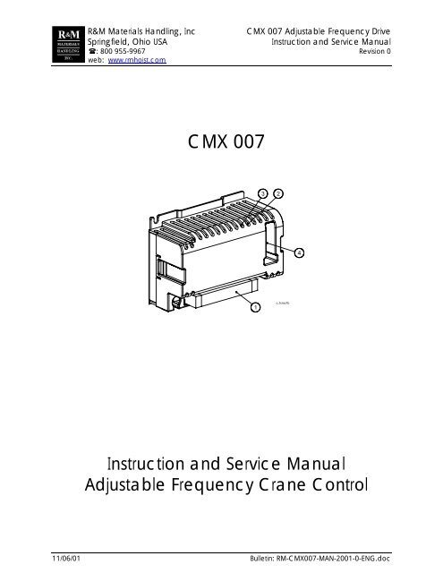
R&M <strong>Materials</strong> <strong>Handling</strong>, Inc CMX 007 Adjustable Frequency Drive<br />
Springfield, Ohio USA<br />
Instruction and Service Manual<br />
: 800 955-9967 Revision 0<br />
web: www.rmhoist.com<br />
CMX 007<br />
c_fcmo1b<br />
Instruction and Service Manual<br />
Adjustable Frequency Crane Control<br />
11/06/01 Bulletin: RM-CMX007-MAN-2001-0-ENG.doc
R&M <strong>Materials</strong> <strong>Handling</strong>, Inc CMX 007 Adjustable Frequency Drive<br />
Springfield, Ohio USA<br />
Instruction and Service Manual<br />
: 800 955-9967 Revision 0<br />
web: www.rmhoist.com<br />
Keep the instructions in a safe place for future reference.<br />
Table of content<br />
1 Description of the Inverter .................................................................................................. 3<br />
1.1 Connections ...................................................................................................................... 3<br />
1.2 Normal Operation for Trolley/Crane................................................................................... 4<br />
1.3 LED’s Status Indication ..................................................................................................... 4<br />
1.4 Compact Brake Motor ....................................................................................................... 4<br />
2 Programming Parameters ................................................................................................... 5<br />
2.1 Programming Speeds and Ramp Time ............................................................................. 5<br />
2.1.1 Frequency Output Selection (Set Switches S1 and S2)...................................................................5<br />
2.1.2 Acceleration and Deceleration Ramp Time......................................................................................6<br />
2.2 Speed Control Mode ......................................................................................................... 6<br />
2.3 Motor Parameters .............................................................................................................7<br />
3 Fault Codes and Troubleshooting...................................................................................... 8<br />
4 Wiring Specification ............................................................................................................ 9<br />
4.1 Wiring Practices ................................................................................................................ 9<br />
11/06/01 2<br />
RM-CMX007-MAN-2001-0-ENG.doc
R&M <strong>Materials</strong> <strong>Handling</strong>, Inc CMX 007 Adjustable Frequency Drive<br />
Springfield, Ohio USA<br />
Instruction and Service Manual<br />
: 800 955-9967 Revision 0<br />
web: www.rmhoist.com<br />
1 Description of the Inverter<br />
1 Do not touch any circuit components while the main AC power is on. High voltages<br />
are supplied to the inverter (including the programming switches). Wait for at least<br />
three minutes after the supply voltage has been switched off before performing any<br />
service on the unit. Failure to adhere to this warning can result in injury.<br />
1. Terminal X1<br />
2. Red led (fault)<br />
3. Green led (ok)<br />
4. Programming switches<br />
c_fcmo1b<br />
1 Inverter cooling is optimal when the air flows through the device from the bottom to<br />
the top. If the inverter is mounted sideways, the output current must be de-rated by<br />
40%.<br />
1.1 Connections<br />
The necessary supply voltage for the inverter is 380/480V 50/60Hz. For other available three phase<br />
voltages, a transformer is provided to supply the proper power to the inverter.<br />
Power and control circuit connections are made to terminal block X1 as follows:<br />
Number Name Description<br />
1 PE Ground<br />
2 L1 Power phase 1. 380-480V 50/60Hz.<br />
3 L2 Power phase 2. 380-480V 50/60Hz.<br />
4 L3 Power phase 3. 380-480V 50/60Hz.<br />
5 U Motor phase 1.<br />
6 V Motor phase 2.<br />
7 W Motor phase 3.<br />
8 S1 Drive command. Direction 1. 48V or 115V 50/60Hz<br />
9 S2 Drive command. Direction 2. 48V or 115V 50/60Hz<br />
10 SP2/AP Speed 2 / Acceleration command. 48V or 115V 50/60Hz<br />
11 ON Control voltage, neutral.<br />
1 WARNING! Inverter must not be connected to following types of power sources:<br />
G Isolated ground system<br />
G High-impedance grounded system<br />
G Phase grounded/grounded leg system.<br />
Use the special, modified version for these power supplies. See product code.<br />
A minimum of two collectors for each runway conductor shall be furnished with inverter use.<br />
11/06/01 3<br />
RM-CMX007-MAN-2001-0-ENG.doc
R&M <strong>Materials</strong> <strong>Handling</strong>, Inc CMX 007 Adjustable Frequency Drive<br />
Springfield, Ohio USA<br />
Instruction and Service Manual<br />
: 800 955-9967 Revision 0<br />
web: www.rmhoist.com<br />
1.2 Normal Operation for Trolley/Crane<br />
The CMX inverter goes into Ready-to-Run within one second after power is applied to the inverter. During<br />
running, CMX 007 follows the user defined speed control mode (Section 2.2). The default speed control<br />
mode is the Two-step Infinitely Variable (EP-2). The stopping method, which the user cannot change on<br />
CMX 007, is always Decelerate at STOP command (dynamic braking). During an immediate direction<br />
change, the brake is always kept open. When the RUN Forward/Reverse command is removed, the<br />
inverter decelerates to zero according to its preset ramp time and then the brake sets.<br />
1.3 LED Status Indicator<br />
CMX indicates its operating status by two LEDs. A steady green LED indicates Ready-to-Run. A blinking<br />
green LED indicates that a fault condition had been active, but the fault has since recovered (See Section<br />
3). Normal operation is possible when the green LED is blinking. A blinking red LED indicates a severe<br />
fault condition and operation is inhibited. The blinking pattern tells the user the type of fault that has<br />
occurred. (See Section 3).<br />
1.4 Compact Brake Motor<br />
CMX 007 is used only with the MF06 compact brake motors. These compact brake motors are specially<br />
designed for inverter use only. The compact brake motors have the following special features:<br />
G<br />
G<br />
The motor brake is opened by the magnetic force of the energized motor. When the magnetic force is<br />
removed (by cutting off the motor current), the brake is closed by a spring force.<br />
High nominal frequency (80Hz…120Hz)<br />
c_r1tm1b<br />
11/06/01 4<br />
RM-CMX007-MAN-2001-0-ENG.doc
R&M <strong>Materials</strong> <strong>Handling</strong>, Inc CMX 007 Adjustable Frequency Drive<br />
Springfield, Ohio USA<br />
Instruction and Service Manual<br />
: 800 955-9967 Revision 0<br />
web: www.rmhoist.com<br />
2 Programming Parameters<br />
1 Do not touch any circuit components while the main AC power is on. High voltages<br />
are supplied to the inverter (including the programming switches). Wait for at least<br />
three minutes after the supply voltage has been switched off before performing any<br />
service on the unit. Failure to adhere to this warning can result in injury.<br />
Before shipping the unit to you, the parameters are set at the factory, which may be different from the<br />
default settings, to meet the performance requirements for your crane application.<br />
CMX uses DipSwitches to program the features. The state of each switch is either OFF (0) or ON (1).<br />
There are five parameters that are possible to set by switches S1 through S4.<br />
Switch S1 = Maximum speed, upper frequency output<br />
setting<br />
Switch S2 = Minimum speed, lower frequency output<br />
setting<br />
Switch S3 = Acceleration / Deceleration Ramp Time<br />
Switch S4 = Control Mode (S4-1) and Motor Parameters<br />
1 2 3 4<br />
1 2 3 4<br />
1 2 3 4<br />
ON DIP<br />
ON DIP<br />
ON DIP<br />
S1<br />
S2<br />
S3<br />
ON<br />
DIP<br />
1 2 3 4<br />
S4<br />
2.1 Speeds and Ramp Time Selections<br />
2.1.1 Frequency Output Selection (Set Switches S1 and S2)<br />
The minimum and maximum speeds are selected by setting the minimum output frequency and the<br />
maximum output frequency. Switch S1 sets the maximum output frequency selection and Switch S2 sets<br />
the minimum frequency selection. Table “A” is used for the 100/120Hz motors and table “B” for the 80Hz<br />
motors.<br />
Switch<br />
S1 / S2<br />
SPEED TABLE A<br />
(100/120Hz motors)<br />
SPEED TABLE B<br />
(80Hz motors)<br />
-1 -2 -3 -4 Max speed, S1 Min speed, S2 Max speed, S1 Min speed, S2<br />
0 0 0 0 100 Hz 29 Hz 77 Hz 22 Hz<br />
0 0 0 1 50 Hz 14 Hz 42 Hz 14 Hz<br />
0 0 1 0 62 Hz 23 Hz 50 Hz 18 Hz<br />
0 0 1 1 54 Hz 10 Hz 40 Hz 10 Hz<br />
0 1 0 0 80 Hz 32 Hz 62 Hz 30 Hz<br />
0 1 0 1 58 Hz 12 Hz 44 Hz 12 Hz<br />
0 1 1 0 66 Hz 16 Hz 46 Hz 16 Hz<br />
0 1 1 1 70 Hz 18 Hz 48 Hz 20 Hz<br />
1 0 0 0 115 Hz *) 50 Hz 80 Hz 40 Hz<br />
1 0 0 1 75 Hz 20 Hz 53 Hz 24 Hz<br />
1 0 1 0 85 Hz 26 Hz 56 Hz 26 Hz<br />
1 0 1 1 90 Hz 35 Hz 59 Hz 28 Hz<br />
1 1 0 0 95 Hz 38 Hz 65 Hz 32 Hz<br />
1 1 0 1 105 Hz *) 41 Hz 68 Hz 34 Hz<br />
1 1 1 0 110 Hz *) 44 Hz 71 Hz 36 Hz<br />
1 1 1 1 120 Hz *) 47 Hz 74 Hz 38 Hz<br />
*) 100 Hz may be exceeded only if voltage to inverter is 460-480V.<br />
11/06/01 5<br />
RM-CMX007-MAN-2001-0-ENG.doc
R&M <strong>Materials</strong> <strong>Handling</strong>, Inc CMX 007 Adjustable Frequency Drive<br />
Springfield, Ohio USA<br />
Instruction and Service Manual<br />
: 800 955-9967 Revision 0<br />
web: www.rmhoist.com<br />
EXAMPLE OF PARAMETER SETTING:<br />
80Hz motor is connected to the inverter and 62Hz<br />
maximum speed is desired. That speed is located on<br />
the 5 th row in the speed table B. The corresponding<br />
setting for S1 switches is in the same row in the<br />
leftmost columns of the table: 0-1-0-0 (off-on-off-off).<br />
ON DIP<br />
1 2 3 4<br />
S1<br />
Max speed set to 62Hz.<br />
2.1.2 Acceleration and Deceleration Ramp Time<br />
The acceleration and deceleration ramp times are set by switch S3 as follows:<br />
Switch S3<br />
Acceleration/deceleration<br />
-1 -2 -3 -4 ramp time<br />
0 0 0 0 2.5 sec<br />
0 0 0 1 3.5 sec<br />
0 0 1 0 3.0 sec<br />
0 0 1 1 5.0 sec<br />
0 1 0 0 2.0 sec<br />
0 1 0 1 8.0 sec<br />
0 1 1 0 1.0 sec<br />
0 1 1 1 7.5 sec<br />
1 0 0 0 1.5 sec<br />
1 0 0 1 4.0 sec<br />
1 0 1 0 7.0 sec<br />
1 0 1 1 6.5 sec<br />
1 1 0 0 4.5 sec<br />
1 1 0 1 6.0 sec<br />
1 1 1 0 5.5 sec<br />
1 1 1 1 0.5 sec<br />
The default setting for the acceleration and deceleration ramp time is 4.0 seconds. The acceleration ramp<br />
time always equals the deceleration ramp time.<br />
CMX 007 stopping method is always the Deceleration at STOP command (dynamic braking) and extreme<br />
caution should be used taking into consideration the value of switch S3. If the deceleration time is too<br />
long, crane/hoist can crash into the end stops, causing damage to <strong>equipment</strong> or injury to personnel.<br />
2.2 Speed Control Mode<br />
CMX 007 provides the user with the flexibility for selection of either a Two-step Multi-Step Speed Control<br />
(MS-2) or a Two-step Infinitely Variable (EP-2) mode. Speed control mode is set by Switch S4-1. The<br />
default speed control selection is the Two-step Infinitely variable (EP-2).<br />
Multi-Step Speed Control Mode (MS-2) (S4-1 = OFF)<br />
CMX 007 provides for only 2 speeds in the Multi-Step Speed Control Mode and for Decelerate at STOP<br />
command stopping method.<br />
G<br />
G<br />
G<br />
G<br />
G<br />
S1 input is “RUN forward”. Frequency output increases to frequency (minimum speed) set by DIP<br />
switch S2. Operation continues at this frequency (minimum speed).<br />
S2 input is “RUN reverse”. Frequency output increases to frequency (minimum speed) set by DIP<br />
switch S2. Operation continues at this frequency (minimum speed).<br />
SP2 input/second speed command. Frequency (speed) output increases to frequency (maximum<br />
speed) set by DIP switch S1. Operation continues at this frequency (maximum speed).<br />
Removal of SP2 input/second speed command. Frequency (speed) output decreases to frequency set<br />
by DIP switch S2. Operation continues at this frequency (minimum speed).<br />
Removal of S1 input and S2 input, Run Forward/Reverse. Deceleration at STOP command, and then<br />
brake sets.<br />
11/06/01 6<br />
RM-CMX007-MAN-2001-0-ENG.doc
R&M <strong>Materials</strong> <strong>Handling</strong>, Inc CMX 007 Adjustable Frequency Drive<br />
Springfield, Ohio USA<br />
Instruction and Service Manual<br />
: 800 955-9967 Revision 0<br />
web: www.rmhoist.com<br />
Two-step Infinitely Variable Speed Control (EP-2) (S4-1 = ON)<br />
CMX 007 provides for Two-step Infinitely Variable Speed Control and Decelerate at STOP command.<br />
fwd<br />
Pushbutton position:<br />
Rest = decelerate<br />
1.step = maintain speed<br />
2.step = accelerate<br />
rev<br />
speed<br />
pushbutton position<br />
time<br />
G<br />
G<br />
G<br />
G<br />
G<br />
S1 input is “Run forward”. Frequency output increases to frequency (minimum speed) set by DIP<br />
switch S2. Operation continues at this frequency (minimum speed).<br />
S2 input is “RUN reverse”. Frequency output increases to frequency (minimum speed) set by DIP<br />
switch S2. Operation continues at this frequency (minimum speed).<br />
AP input is acceleration. Frequency (speed) output increases. The longer this contact is closed, the<br />
higher the speed output becomes. Limited only by the setting if DIP switch S2.<br />
During run time S1 input and S2 input is hold speed. Frequency output remains constant.<br />
Removal of S1 input and S2 input, RUN Forward/Reverse. Decelerate at STOP command. Output<br />
frequency decreases and the inverter decelerates to zero, and brake will set.<br />
2.3 Motor Parameters<br />
The motor parameters are selected by setting switches S4-2, S4-3 and S4-4. The motor parameters must<br />
correspond to the motor type being used. The motor parameters are selected as follows:<br />
Switch S4<br />
-2 -3 -4<br />
Motor type Nominal frequency Nominal Motor<br />
power<br />
0 0 0 MF06MA200 100Hz (120Hz) 0.3kW (0.37kW)<br />
1 0 0 MF06MA100 80Hz 0.45kW<br />
0 1 0 MF06LA200 100Hz (120Hz) 0.45kW (0.55kW)<br />
1 1 0 MF06LA100 80Hz 0.45kW (0.55kW)<br />
0 0 1 2*MF06MA200 100Hz (120Hz) 2*0.3kW (2*0.37kW)<br />
11/06/01 7<br />
RM-CMX007-MAN-2001-0-ENG.doc
R&M <strong>Materials</strong> <strong>Handling</strong>, Inc CMX 007 Adjustable Frequency Drive<br />
Springfield, Ohio USA<br />
Instruction and Service Manual<br />
: 800 955-9967 Revision 0<br />
web: www.rmhoist.com<br />
3 Fault Codes and Troubleshooting<br />
1 Do not touch any circuit components while the main AC power is on. High voltages<br />
are supplied to the inverter (including the programming switches). Wait for at least<br />
three minutes after the supply voltage has been switched off before performing any<br />
service on the unit. Failure to adhere to this warning can result in injury.<br />
If CMX malfunctions, a fault lamp blinks on and off. The blinking pattern continues until a new fault occurs<br />
or until power is switched off. The fault codes are explained in the table below.<br />
LED Color, Blinking Pattern Possible cause. What to do.<br />
GREEN<br />
Overvoltage.<br />
Supply voltage exceeds the specification Lower input voltage.<br />
GREEN<br />
allows.<br />
Deceleration ramp time is too short.<br />
Extend Deceleration time.<br />
GREEN<br />
GREEN<br />
GREEN<br />
GREEN<br />
RED<br />
RED<br />
Stall supervision / overcurrent.<br />
Brake does not open properly or an<br />
obstacle is on the track.<br />
Incorrect motor dependent parameter setup.<br />
Deceleration ramp supervision.<br />
Deceleration ramp has not been followed.<br />
Power voltage exceeds specification allows.<br />
Inverter overtemperature.<br />
Motor current is too high (bearing problem,<br />
obstacle on the track, brake does not open<br />
properly).<br />
Ambient temperature is too high.<br />
Undervoltage.<br />
Supply voltage < specification allows<br />
Short circuit.<br />
Break down in motor cable insulation.<br />
Break down in motor winding insulation.<br />
Microprosessor fault.<br />
Due to high electrical noise environment.<br />
Adjust air gap. Repair/replace brake.<br />
Check that the motor parameter settings<br />
(switch S4) are made according to the<br />
supplied motor(s). Section 2.3<br />
Reset to longer Deceleration ramp time.<br />
Check the voltage of all supply phases<br />
at the terminal X1.<br />
Repair bearing problem. Remove<br />
obstacle. Adjust air gap or repair or<br />
replace brake.<br />
Use a larger rated inverter.<br />
Correct the input power supply problem.<br />
Check for single-phase problem.<br />
Switch main power off.<br />
Replace the motor cables.<br />
Check motor resistance. Replace the<br />
motor.<br />
Switch power off for 10 seconds, then<br />
back on.<br />
NOTE! The latest active fault is always removed from the memory when power is switched off.<br />
1 Drive will not run even though inverter is not in a fault condition:<br />
Motor will not start if DC-bus voltage too high (above 745V), this occurs if any line-to-line voltage<br />
exceeds 480V+10% = 528V. If line voltage cannot be reduced, install step-down transformer.<br />
Check the supply voltage phases at terminal X1.<br />
Check the control signals at terminal X1.<br />
Check that the control voltage is correct. Rating plate is located on the left side of the inverter.<br />
Check all parameter selections, especially the motor parameters (switch S4).<br />
Check that the selected motor parameters (switch S4) correspond to the proper motor type.<br />
Check that the microprocessor starts running. Both the green and red indicator LED’s blink once as<br />
the inverter is powered up. After the one second initializing-time only the green LED should be light.<br />
Check that the brake opens and closes properly. Check the brake air gap.<br />
11/06/01 8<br />
RM-CMX007-MAN-2001-0-ENG.doc
R&M <strong>Materials</strong> <strong>Handling</strong>, Inc CMX 007 Adjustable Frequency Drive<br />
Springfield, Ohio USA<br />
Instruction and Service Manual<br />
: 800 955-9967 Revision 0<br />
web: www.rmhoist.com<br />
4 Wiring Specification<br />
4.1 Wiring Practices<br />
G Do not connect incoming three-phase AC power to the drive output terminals U, V or W.<br />
G<br />
G<br />
G<br />
G<br />
G<br />
G<br />
G<br />
G<br />
G<br />
G<br />
G<br />
Do not ground the AFD with any large-current machines.<br />
Before you use any welding or high-current machines near the crane, disconnect all line and ground<br />
wiring.<br />
Do not use output contactors between the AFD and the motor.<br />
Do not connect power factor correction capacitors to the drive input or output.<br />
Before turning on the AFD, check the output circuit (U, V, and W) for possible short circuits and<br />
ground faults.<br />
When using more than one transformer for the AFD’s power, properly phase each transformer.<br />
To reverse the direction of rotation, interchange any two motor leads (U, V, or W). Changing input<br />
leads (L1, L2, or L3) will not affect the shaft rotation direction.) Ensure that the motion is in proper<br />
direction with respect to the push button being pressed.<br />
AFD line voltage inputs (L1, L2 and L3) are voltage specific. Do not connect the wrong voltage to the<br />
unit.<br />
A minimum of two collectors for each runway conductor shall be furnished with inverter use.<br />
Always mount the AFD in its proper vertical orientation so that the unit cools from bottom to top.<br />
Keep AFD heatsink clear of any obstructions (components on panel) to ensure proper cooling airflow.<br />
11/06/01 9<br />
RM-CMX007-MAN-2001-0-ENG.doc