Stehle BA J5 HTM_dt_en_fr_Lay5 - Rollo Rieper
Stehle BA J5 HTM_dt_en_fr_Lay5 - Rollo Rieper
Stehle BA J5 HTM_dt_en_fr_Lay5 - Rollo Rieper

You also want an ePaper? Increase the reach of your titles
YUMPU automatically turns print PDFs into web optimized ePapers that Google loves.
Betriebsanleitung für <strong>Stehle</strong><br />
Jalousie- und Raffstor<strong>en</strong>antriebe<br />
der Baureih<strong>en</strong> <strong>J5</strong> <strong>HTM</strong><br />
Operating instructions for <strong>Stehle</strong> blind<br />
and V<strong>en</strong>etian blind drives of the <strong>J5</strong> <strong>HTM</strong><br />
Notice d’utilisation des moteurs pour stores véniti<strong>en</strong>s<br />
d’intérieur et d’extérieur des séries <strong>J5</strong> <strong>HTM</strong><br />
1.0 Wichtige Sicherheitsanweisung<strong>en</strong><br />
Achtung – für die Sicherheit von<br />
Person<strong>en</strong> ist es wichtig, diese<br />
Anweisung<strong>en</strong> zu befolg<strong>en</strong> und<br />
aufzubewahr<strong>en</strong><br />
➮ Warnhinweise analog<br />
zu EN 60335-2-97<br />
1.1 Wichtige Sicherheitsanweisung<strong>en</strong><br />
für die Montage<br />
Achtung – falsche Montage kann zu<br />
ernsthaft<strong>en</strong> Verletzung<strong>en</strong> führ<strong>en</strong>.<br />
Alle Montageanweisung<strong>en</strong> befolg<strong>en</strong>.<br />
Bevor der Antrieb installiert wird, sind alle<br />
nicht b<strong>en</strong>ötigt<strong>en</strong> Leitung<strong>en</strong> zu <strong>en</strong>tfern<strong>en</strong>.<br />
Schalter, Taster oder Steuerung<strong>en</strong> sind nicht<br />
im Lieferumfang des Antriebes <strong>en</strong>thalt<strong>en</strong>.<br />
Beweg<strong>en</strong>de Teile von Antrieb<strong>en</strong><br />
die unter einer Höhe von 2,5 m vom Bod<strong>en</strong><br />
betrieb<strong>en</strong> werd<strong>en</strong>, müss<strong>en</strong> geschützt sein.<br />
Die Einbauart des Antriebes ist mit dem<br />
Hersteller abzustimm<strong>en</strong>.<br />
1.0 Important safety<br />
instructions<br />
Please note – for the safety of<br />
personnel, it is important to follow<br />
these instructions and to keep<br />
them in a safe place<br />
➮ Warnings analagous<br />
to EN 60335-2-97<br />
1.1 Important safety instructions for<br />
assembly<br />
Please note – incorrect assembly can lead<br />
to serious injuries. Follow all assembly instructions.<br />
Before the drive unit is installed, all<br />
leads that are not required must be removed.<br />
Switches, buttons or controls are not included<br />
in the drive unit as delivered.<br />
Moving parts<br />
which are to be operated below a height of<br />
2.5 metres <strong>fr</strong>om the ground must be protected.<br />
The type of installation of the drive unit<br />
should be clarified with the manufacturer.<br />
1.0 Instructions de sécurité<br />
importantes<br />
Att<strong>en</strong>tion – pour la sécurité des<br />
personnes, il est important de suivre<br />
ces instructions et de les conserver<br />
dans un lieu sûr<br />
➮ Avertissem<strong>en</strong>t analogue<br />
à EN 60335-2-97<br />
1.1 Instructions de sécurité<br />
importantes pour le montage<br />
Att<strong>en</strong>tion – un montage incorrect peut<br />
provoquer de graves blessures. Suivre toutes<br />
les instructions de montage. Avant d’installer<br />
du moteur, <strong>en</strong>lever tous les câbles qui ne sont<br />
pas nécessaires. Interrupteurs, boutons<br />
ou commandes ne font pas partie du cont<strong>en</strong>u<br />
de la livraison du moteur.<br />
Protéger les pièces mobiles<br />
des moteurs<br />
devant être actionnés à une hauteur<br />
inférieure à 2,5 m du sol. Mettre au<br />
point le mode d’installation du moteur <strong>en</strong><br />
collaboration avec le fabricant.<br />
02.2005<br />
<strong>J5</strong> <strong>HTM</strong> <strong>BA</strong>.01
1.2 Dat<strong>en</strong> der Antriebe<br />
– Sind auf d<strong>en</strong> Typ<strong>en</strong>schildern verzeichnet<br />
➮ Dürf<strong>en</strong> nicht überschritt<strong>en</strong> werd<strong>en</strong><br />
1.3 Überfahr<strong>en</strong> der Endschalter:<br />
– Kann zum Abriss der Tragelem<strong>en</strong>te führ<strong>en</strong><br />
– Es besteht dadurch eine Gefahr durch<br />
herabstürz<strong>en</strong>de Teile<br />
➮ Die Tragelem<strong>en</strong>te ausreich<strong>en</strong>d<br />
dim<strong>en</strong>sionier<strong>en</strong><br />
1.4 Lauf<strong>en</strong>de Welle des<br />
Gesamtsystems<br />
Es besteht Verletzungsgefahr bei:<br />
– Einbau ins System<br />
– Inbetriebnahme<br />
– Reparaturarbeit<strong>en</strong><br />
➮ Bei Reparaturarbeit<strong>en</strong> am<br />
Gesamtsystem spannungs<strong>fr</strong>ei<br />
schalt<strong>en</strong> oder nur mit<br />
Tastschaltern betätig<strong>en</strong><br />
1.5 Gefahr eines Stromschlages<br />
– Bei Isolationsfehler der Antriebe<br />
– Bei Isolationsbeschädigung<br />
– Bei Berührung spannungsführ<strong>en</strong>der Teile<br />
➮ Vor der Inbetriebnahme<br />
Schutzleiteranschluss überprüf<strong>en</strong><br />
1.6 Brandgefahr<br />
– Entzündung der bauseitig umgeb<strong>en</strong>d<strong>en</strong><br />
Systemteile bei Ausfall des intern<strong>en</strong><br />
Temperaturbegr<strong>en</strong>zers<br />
➮ Verw<strong>en</strong>dung geeigneter<br />
Werkstoffe in der unmittelbar<strong>en</strong><br />
Umgebung der Antriebe<br />
1.7 Hinweise für Systemanbieter<br />
Bedi<strong>en</strong>ungsanleitung für Endverbraucher<br />
muss folg<strong>en</strong>d<strong>en</strong> Hinweis <strong>en</strong>thalt<strong>en</strong>:<br />
– Kindern nicht erlaub<strong>en</strong>, mit ortsfest<strong>en</strong><br />
Steuerung<strong>en</strong> zu spiel<strong>en</strong>. Fernsteuerung<strong>en</strong><br />
von Kindern fernhalt<strong>en</strong>.<br />
– Die Anlage ist regelmäßig auf Anzeich<strong>en</strong><br />
von Verschleiß oder beschädigt<strong>en</strong> Teil<strong>en</strong><br />
zu überprüf<strong>en</strong>.<br />
1.8 Beacht<strong>en</strong> Sie die Hinweise in<br />
d<strong>en</strong> Steuerungsunterlag<strong>en</strong><br />
1.2 Drive unit specifications<br />
– Are indicated on the type plate<br />
➮ Must not be exceeded<br />
1.3 Exceeding the limit switches<br />
– Can lead to the supporting elem<strong>en</strong>ts<br />
rupturing<br />
– This would result in the risk of falling parts<br />
➮ The supporting elem<strong>en</strong>ts should be<br />
of suffici<strong>en</strong>t size<br />
1.4 Moving shaft of the overall<br />
system<br />
There is a risk of injury wh<strong>en</strong>:<br />
– fitting it into the system<br />
– using the system<br />
– carrying out repairs<br />
➮ Wh<strong>en</strong> carrying out repair work<br />
on the overall system, disconnect<br />
<strong>fr</strong>om the power supply or operate<br />
using only push-buttons<br />
1.5 Danger of electric shock<br />
– With drive unit insulation defects<br />
– With damaged insulation<br />
– Wh<strong>en</strong> coming into contact with live<br />
compon<strong>en</strong>ts<br />
➮ Check earthing conductor<br />
connection before using<br />
1.6 Risk of fire<br />
– Ignition of factory-fitted surrounding system<br />
compon<strong>en</strong>ts in the ev<strong>en</strong>t of a failure of the<br />
internal temperature limiter<br />
➮ Use of suitable materials immediately<br />
surrounding the drive units<br />
1.7 Instructions for system suppliers<br />
Operating instructions for <strong>en</strong>d-users must<br />
contain the following remarks:<br />
– Do not allow childr<strong>en</strong> to play with fixed<br />
controls. Keep remote controls out of the<br />
reach of childr<strong>en</strong>.<br />
– The system should be regularly checked<br />
for signs of wear and tear or damaged<br />
compon<strong>en</strong>ts.<br />
1.8 Read carefully through<br />
the instructions<br />
in the control docum<strong>en</strong>ts<br />
1.2 Données relatives aux moteurs<br />
– sont indiquées sur les plaques signalétiques<br />
indiquant le type<br />
➮ ne doiv<strong>en</strong>t pas être dépassées<br />
1.3 Le dépassem<strong>en</strong>t des limites de<br />
l’interrupteur de fin de course<br />
– peut conduire à la rupture<br />
des élém<strong>en</strong>ts porteurs<br />
– Cela a pour résultat d’<strong>en</strong>traîner<br />
un risque dû à la chute des pièces<br />
➮ Les élém<strong>en</strong>ts porteurs doiv<strong>en</strong>t prés<strong>en</strong>ter<br />
des dim<strong>en</strong>sions suffisantes<br />
1.4 Axe mobile de l’<strong>en</strong>semble<br />
du système<br />
Il y a un risque de blessures lors :<br />
– du montage dans le système<br />
– de la mise <strong>en</strong> service du système,<br />
– de travaux de réparation<br />
➮ Lors de l’exécution de travaux de<br />
réparation sur l’<strong>en</strong>semble du<br />
système, mettre l’alim<strong>en</strong>tation<br />
hors t<strong>en</strong>sion ou procéder à la<br />
manœuvre seulem<strong>en</strong>t à l’aide du<br />
bouton poussoir<br />
1.5 Risque décharge électrique<br />
– lorsque l’isolation des moteurs<br />
est défectueuse<br />
– lorsque l’isolation prés<strong>en</strong>te<br />
des détériorations<br />
– <strong>en</strong> cas de contact avec des pièces<br />
sous t<strong>en</strong>sion<br />
➮ Avant la mise <strong>en</strong> service,<br />
vérifier le raccordem<strong>en</strong>t à la terre<br />
1.6 Risque d’inc<strong>en</strong>die<br />
– Les élém<strong>en</strong>ts de la construction <strong>en</strong>tourant<br />
les pièces du système peuv<strong>en</strong>t s’<strong>en</strong>flammer<br />
<strong>en</strong> cas de panne du thermostat<br />
➮ Utilisation de matériaux adaptés<br />
dans l’<strong>en</strong>vironnem<strong>en</strong>t immédiat<br />
des moteurs<br />
1.7 Consignes pour les fournisseurs<br />
de système<br />
Les instructions de service pour l’utilisateur<br />
final doiv<strong>en</strong>t cont<strong>en</strong>ir les consignes suivantes:<br />
– Ne pas autoriser les <strong>en</strong>fants à jouer avec<br />
les commandes fixes. Conserver la télécommande<br />
hors de la portée des <strong>en</strong>fants.<br />
– Contrôler régulièrem<strong>en</strong>t l’apparition de<br />
signes d’usure ou de pièces <strong>en</strong>dommagées<br />
1.8 Observer les consignes données<br />
dans les docum<strong>en</strong>ts de<br />
la commande<br />
02.2005<br />
<strong>J5</strong> <strong>HTM</strong> <strong>BA</strong>.02
2.0 Elektrischer Anschluss<br />
– Ist vom Fachunternehmer nach d<strong>en</strong><br />
allgemein<strong>en</strong>, örtlich<strong>en</strong> und d<strong>en</strong><br />
Landesvorschrift<strong>en</strong> durchzuführ<strong>en</strong><br />
– Ist nach dem am Gerät befindlich<strong>en</strong><br />
Anschlussplan durchzuführ<strong>en</strong><br />
– Ist mit allpoliger Tr<strong>en</strong>nung der Antriebe<br />
vom Netz durchzuführ<strong>en</strong><br />
– Bei Drehrichtungsänderung muss die<br />
Umschaltverzögerung mindest<strong>en</strong>s 500 ms<br />
(spannungs<strong>fr</strong>ei) betrag<strong>en</strong>.<br />
Bei Falschanschluss werd<strong>en</strong> die<br />
Antriebe beschädigt<br />
2.1 Installationsmaterial:<br />
– Muss d<strong>en</strong> speziell<strong>en</strong> Anforderung<strong>en</strong> der<br />
Antriebe g<strong>en</strong>üg<strong>en</strong><br />
– Kontaktöffnungsweite >3 mm pro Pol,<br />
bei Schaltern zur direkt<strong>en</strong> Betätigung<br />
– Nur geg<strong>en</strong>seitig verriegelte Taster oder<br />
Schalter verw<strong>en</strong>d<strong>en</strong><br />
2.2 Spannungsversorgung:<br />
– Netzspannung muss<br />
230 V +/- 10% / 50 Hz betrag<strong>en</strong><br />
– Geeignete Filter einsetz<strong>en</strong>, bei nicht normgerechter<br />
Netzspannung<br />
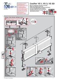
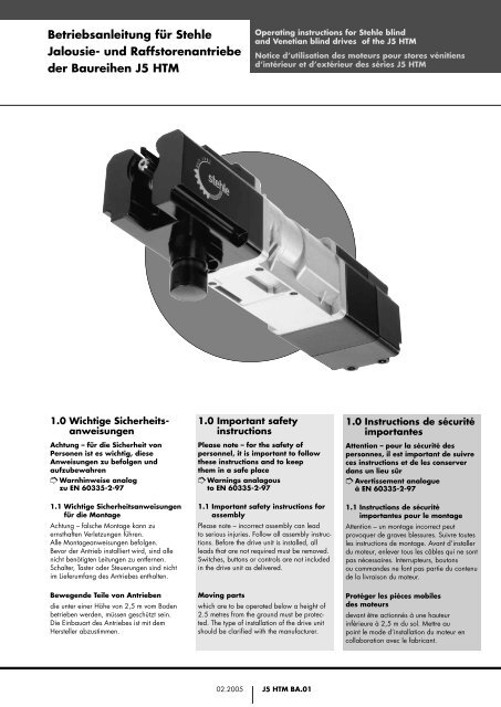
3.0 Ausführung <strong>HTM</strong>/<br />
Endlag<strong>en</strong>einstellung<br />
Endposition OBEN<br />
D<strong>en</strong> schwarz<strong>en</strong> Einstelltaster drück<strong>en</strong><br />
(er bleibt dann gedrückt), dann fahr<strong>en</strong><br />
(Fahrweg mind. 0,3 m) in die obere<br />
Endposition (die Fahrt kann unterbroch<strong>en</strong><br />
werd<strong>en</strong> und auch im Tippbetrieb gefahr<strong>en</strong><br />
werd<strong>en</strong>), bei Drehrichtungsumkehr d. h.<br />
Fahrtrichtung nach unt<strong>en</strong> rastet der Einstelltaster<br />
aus und die Position ist eingestellt.<br />
Endposition UNTEN<br />
D<strong>en</strong> weiß<strong>en</strong> Einstelltaster drück<strong>en</strong> (er bleibt<br />
dann gedrückt), dann fahr<strong>en</strong> (Fahrweg mind.<br />
0,3 m) in die untere Endposition (die Fahrt<br />
kann unterbroch<strong>en</strong> werd<strong>en</strong> und auch im<br />
Tippbetrieb gefahr<strong>en</strong> werd<strong>en</strong>), bei Drehrichtungsumkehr<br />
d. h. Fahrtrichtung nach ob<strong>en</strong><br />
rastet der Einstelltaster aus und die Position<br />
ist eingestellt.<br />
Werksseitige Einstellung<br />
UNTERE Position erfolgt bei der Auslieferung<br />
in der Position NULLSTELLUNG<br />
OBERE Position 10 Umdrehung<strong>en</strong> der<br />
Abtriebswelle ab Nullstellung<br />
Endschalterkapazität<br />
Max. 90 Umdrehung<strong>en</strong> der Abtriebswelle<br />
2.0 Electrical connection<br />
– Is to be carried out by a qualified person<br />
in accordance with the g<strong>en</strong>eral, local and<br />
regional regulations<br />
– Is to be carried out in accordance with the<br />
connection plan attached to the unit<br />
– Is to be carried out after first completely<br />
disconnecting the drive units <strong>fr</strong>om<br />
the power supply<br />
– With a change in the direction of rotation,<br />
the reversal delay must be at least 500 ms<br />
(<strong>fr</strong>ee of voltage)<br />
If connected incorrectly, the drive<br />
units will be damaged<br />
2.1 Installation material:<br />
– Must meet the special requirem<strong>en</strong>ts of the<br />
drive units<br />
– Wi<strong>dt</strong>h of contact op<strong>en</strong>ing >3 mm per pole,<br />
for switches with direct operation<br />
– Use only interlocking buttons or switches<br />
2.2 Power supply:<br />
– Power supply voltage must be<br />
230 V +/- 10% / 50 Hz<br />
–Use appropriate filters for non-standard<br />
power supply<br />
3.0 Model <strong>HTM</strong>/<br />
End position setting<br />
End position ABOVE<br />
Press the black setting button (it th<strong>en</strong> remains<br />
pressed in), th<strong>en</strong> move (travel distance<br />
min. 30 cm) into the upper <strong>en</strong>d position<br />
(the adjustm<strong>en</strong>t can be interrupted and can<br />
also be carried out in jogging mode), wh<strong>en</strong><br />
the direction of rotation is reversed, i.e. downward<br />
direction of travel, the setting button<br />
clicks out and the position has be<strong>en</strong> set.<br />
End position BELOW<br />
Press the white setting button (it th<strong>en</strong> remains<br />
pressed in), th<strong>en</strong> move (travel distance<br />
min. 30 cm) into the lower <strong>en</strong>d position<br />
(the adjustm<strong>en</strong>t can be interrupted and can<br />
also be carried out in jogging mode), wh<strong>en</strong><br />
the direction of rotation is reversed, i.e.<br />
upward direction of travel, the setting button<br />
clicks out and the position has be<strong>en</strong> set.<br />
Manufacturer’s Settings<br />
LOWER position is in the ZERO position<br />
upon delivery<br />
UPPER position is 10 rotations of the<br />
countershaft <strong>fr</strong>om the zero position<br />
Limit switch capacity<br />
Max. 90 rotations of the countershaft<br />
2.0 Le branchem<strong>en</strong>t<br />
électrique<br />
– Doit être exécuté par une personne<br />
qualifiée conformém<strong>en</strong>t aux prescriptions<br />
générales et locales et régionales;<br />
– Doit être exécuté selon le schéma de<br />
raccordem<strong>en</strong>t accompagnant l’appareil;<br />
– Doit être exécuté après avoir complètem<strong>en</strong>t<br />
déconnecté les moteurs du réseau<br />
d’alim<strong>en</strong>tation;<br />
– Lors d’un changem<strong>en</strong>t de direction de<br />
rotation, le délai d’inversion doit<br />
être d’au moins 500 ms (hors t<strong>en</strong>sion)<br />
Si le branchem<strong>en</strong>t est incorrect,<br />
les moteurs seront <strong>en</strong>dommagés<br />
2.1 Matériel d’installation:<br />
– Doit être adapté aux exig<strong>en</strong>ces spéciales<br />
des moteurs<br />
– Largeur d’intervalle de coupure > 3 mm<br />
par pôle, pour les interrupteurs à<br />
commande directe<br />
– N’utiliser que des boutons ou des<br />
interrupteurs à verrouillage réciproque<br />
2.2 Alim<strong>en</strong>tation <strong>en</strong> courant<br />
– La t<strong>en</strong>sion de réseau doit être<br />
de 230 V +/- 10% / 50 Hz<br />
– Utiliser des filtres appropriés <strong>en</strong> cas de<br />
t<strong>en</strong>sion de réseau non conforme à la norme<br />
3.0 Modèle <strong>HTM</strong>/ Position<br />
de fin de course<br />
Fin de course HAUT<br />
Appuyer sur le bouton de réglage noir<br />
(il reste alors <strong>en</strong> position <strong>en</strong>foncée),<br />
puis déplacer (course d’une distance de<br />
0,3 m minimum) vers la position finale<br />
supérieure (le parcours peut être interrompu<br />
et conduit par impulsions), <strong>en</strong> cas d’inversion<br />
du s<strong>en</strong>s de rotation, c’est-à-dire <strong>en</strong> cas de<br />
marche vers le bas, le bouton de réglage sort<br />
et la position est réglée.<br />
Fin de course <strong>BA</strong>S<br />
Appuyer sur le bouton de réglage blanc<br />
(il reste alors <strong>en</strong> position <strong>en</strong>foncée), puis<br />
déplacer (course d’une distance de 0,3 m<br />
minimum) vers la position finale inférieure<br />
(le parcours peut être interrompu et conduit<br />
par impulsions), <strong>en</strong> cas d’inversion du s<strong>en</strong>s<br />
de rotation, c’est-à-dire <strong>en</strong> cas de marche<br />
vers le haut, le bouton de réglage sort et la<br />
position est réglée.<br />
Réglages à l’usine<br />
La position inférieure est <strong>en</strong> position<br />
zéro à la livraison<br />
La position supérieure est 10 rotations<br />
de l’axe à partir de la position zéro<br />
Nombre de tours de l’axe <strong>en</strong>tre<br />
les fins de course<br />
Max. 90 rotations de l’axe<br />
02.2005<br />
<strong>J5</strong> <strong>HTM</strong> <strong>BA</strong>.03
Einstellung<strong>en</strong> der Endposition<br />
mittels Einstelltaster<br />
End position settings using<br />
the setting button<br />
Réglage de la fin de course au<br />
moy<strong>en</strong> du bouton de réglage<br />
Einstelltaster<br />
setting button<br />
bouton de réglage<br />
Einstelltaster weiß<br />
– fahr<strong>en</strong> in die untere Endposition.<br />
Einstelltaster schwarz/blau<br />
– fahr<strong>en</strong> in die obere Endposition.<br />
Endposition OBEN und UNTEN<br />
über rast<strong>en</strong>de Einstelltaster<br />
UPPER and LOWER <strong>en</strong>d positions<br />
using the locking setting button<br />
Position fin de course HAUT et <strong>BA</strong>S<br />
par le bouton de réglage à verrouillage<br />
White setting button<br />
– moving into the lower <strong>en</strong>d position.<br />
Black / blue setting button<br />
– moving into the upper <strong>en</strong>d position.<br />
Boutons de réglage blanc<br />
– déplac<strong>en</strong>t vers la position fin de course bas<br />
Boutons de réglage noir/bleu<br />
– déplac<strong>en</strong>t vers la position fin de course haut<br />
Anschlußplan<br />
Circuit diagram<br />
Schéma de raccordem<strong>en</strong>t<br />
hot/phase<br />
common/neutre<br />
ground/terre<br />
Steckvorrichtung [VDE 0627]<br />
Plug device<br />
Connecteur<br />
Steckverbinder [VDE 0627]<br />
Plug connection<br />
Connecteur multiple<br />
Leiterk<strong>en</strong>nzeichnung:<br />
Wire Color Codes: 230 V /50<br />
repérage des conducteurs: Hz<br />
1 = blau/blue/bleu<br />
2 = schwarz/black/noir<br />
3 = braun/brown/marron<br />
= grün-gelb/gre<strong>en</strong>-yellow/vert-jaune<br />
Diese Betriebsanleitung wurde nach bestem Wiss<strong>en</strong> und d<strong>en</strong> uns vorlieg<strong>en</strong>d<strong>en</strong> Erfahrung<strong>en</strong> erstellt. Für Irrtümer oder Fehler könn<strong>en</strong> wir keine Haftung übernehm<strong>en</strong>.<br />
Technische Änderung<strong>en</strong> vorbehalt<strong>en</strong>. Stand 02.2005<br />
These operating instructions were produced to the best of our knowledge and based on experi<strong>en</strong>ces with the product available to us.<br />
We assume no liability for possible errors or omissions in the cont<strong>en</strong>ts. Subject to alterations. Release: 02.2005<br />
Ces instructions de service ont été élaborées <strong>en</strong> bonne consci<strong>en</strong>ce et reflèt<strong>en</strong>t les expéri<strong>en</strong>ces dont nous avons connaissance.<br />
Nous déclinons toute responsabilité pour d’év<strong>en</strong>tuelles erreurs et omissions. Sous réserve de modifications. Date: 02. 2005<br />
J. <strong>Stehle</strong>+Söhne GmbH, D-73773 Aichwald, Waldstrasse 26-28<br />
Tel.: ++49 711/9 36 36-0, Fax: ++49 711/9 36 36-10<br />
e-mail: info@stehle.com, www.stehle.com<br />
02.2005<br />
<strong>J5</strong> <strong>HTM</strong> <strong>BA</strong>.04