Frisbee Throwing Device - Rose-Hulman
Frisbee Throwing Device - Rose-Hulman
Frisbee Throwing Device - Rose-Hulman

Create successful ePaper yourself
Turn your PDF publications into a flip-book with our unique Google optimized e-Paper software.
<strong>Frisbee</strong> <strong>Throwing</strong> <strong>Device</strong><br />
Final Report<br />
Submitted to<br />
The Faculty of Catapult LXIII<br />
<strong>Rose</strong>-<strong>Hulman</strong> Institute of Technology<br />
Terre Haute, Indiana<br />
Group 6<br />
Deanna Miller<br />
Andy Welsh<br />
Courtney Thomerson<br />
Isaac Wafzig<br />
University High School<br />
Heyworth, Illinois<br />
Oldenburg Academy<br />
Batesville, Indiana<br />
Lexington Catholic High School<br />
Versailles, Kentucky<br />
Terre Haute South Vigo High School<br />
Terre Haute, Indiana<br />
July 3, 2008
6-1<br />
Introduction<br />
<strong>Frisbee</strong> throwing started in Connecticut with Yale students and a baker. William<br />
Frisbie’s pie pan proved easy to throw and light weight, the perfect combination for a <strong>Frisbee</strong>.<br />
After World War II plastic advancements made it possible to make the <strong>Frisbee</strong> what it is today<br />
(Lorenz, Ralph D. 2006). In order for a <strong>Frisbee</strong> to fly it must spin as it is propelled forward. This<br />
spinning motion is what allows the <strong>Frisbee</strong> to glide through the air and go great distances with<br />
relatively little force. The spin is the characteristic that sets the <strong>Frisbee</strong> apart from a sphere<br />
shaped ball. The historical problem with a <strong>Frisbee</strong>, however, is a person cannot play <strong>Frisbee</strong><br />
with themselves as they can with a ball. The purpose of this project was to construct a device<br />
that would allow a person to play catch with themself. The goal of this device was to mimic the<br />
distance and speed that an average human throws a <strong>Frisbee</strong>. This distance was tested by all<br />
members of the group throwing four <strong>Frisbee</strong>s each, and an average distance of 15 meters was<br />
found from this data. This distance became the goal distance for the device. In building the<br />
device it was also a goal to have it work on its own and have no need for human contact between<br />
throws.<br />
Method<br />
In the process of constructing a <strong>Frisbee</strong> throwing device many prototypes were designed.<br />
The designs were originally complex but became more simplistic as the design process<br />
continued. It was found that more complex and intricate designs proved impractical and unstable.<br />
The number of moving parts required to make the device had to be kept at a minimum to have a<br />
greater chance of success. The transition from complex to simple mainly focused on reducing the<br />
number of moving parts. Three main designs were debated before the final design was approved.<br />
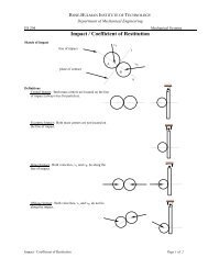
The first design resembled a human arm and was very similar to clay pidgin thrower. It<br />
consisted of an PVC pipe, “arm” with a curved piece of metal “hand” at one end. This assembly<br />
was to be attached to a stationary point at the end opposite the hand. It was then to be spun<br />
around at a high speed and the <strong>Frisbee</strong> would be thrown from the arm. (Fig-1) The curved hand<br />
would give the <strong>Frisbee</strong> the desired spin to make it fly. This design was rejected because of the<br />
complexity of the reload system that would be needed in order to have the device reload a new<br />
<strong>Frisbee</strong> into the hand without human contact.<br />
Side View<br />
Arm Rotation<br />
Plan View<br />
Figure 1-First design of <strong>Frisbee</strong> throwing device
6-2<br />
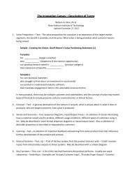
The next design was very similar. In addition to a motor, a spring was used to propel the<br />
arm. (Fig.-2) The motor wound a string around the main shaft the arm was attached to. On the<br />
end of the string was a spring with one stationary end. As the string wound the spring was<br />
stretched. When the motor released the string the spring would recoil and cause the arm to swing<br />
and throw the <strong>Frisbee</strong>. However, the same problem of an overly complex reload system was<br />
found, and this design was also eliminated.<br />
Figure 2-Side of second design<br />
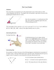
The final design was much like a pitching machine (Fig.-3). It had two wheels spinning<br />
in opposite directions that were spaced the distance of a <strong>Frisbee</strong> apart. The <strong>Frisbee</strong> would be fed<br />
between the wheels and be propelled forward. If the speeds of the individual wheels were<br />
different then the <strong>Frisbee</strong> could spin as well as go forward. A <strong>Frisbee</strong> holder would be erected<br />
behind the device with a chain and hook to pull one <strong>Frisbee</strong> down to the machine at a time. This<br />
design became the final design because it had far fewer moving parts and was not very complex.<br />
Top View<br />
Wheel<br />
↓<br />
Front View<br />
Wheel→<br />
Figure 3- Final design of <strong>Frisbee</strong> throwing device<br />
A <strong>Frisbee</strong> catching device was also considered to remove any physical contact. This<br />
never got past the planning stages due to time constraints and unforeseen problems. The <strong>Frisbee</strong><br />
catcher would have been a simple design involving a net or sheet that was set at a slight angle to<br />
catch the <strong>Frisbee</strong> and allow it to slide into the <strong>Frisbee</strong> container.<br />
Construction<br />
Construction began by building a basic model and then making small modifications as problems<br />
were found. The first problem encountered was that the <strong>Frisbee</strong>s were twisting upon making<br />
contact with the wheels. The first attempt to solve this was to install a single rail made from
6-3<br />
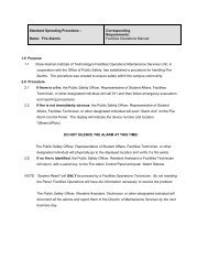
Plexiglas. However, this proved to be inconsistent. The rail was widened to a platform (Fig.-4) to<br />
improve stability and an additional platform was installed on top to further control the disk. A<br />
slot was cut in the middle for later installation of a guide system and cuts had to be made to<br />
accommodate the wheels and PVC supports.<br />
Figure 4- Platform (2 ft x 1ft 2 in)<br />
Once these adjustments were made trials became more consistent and reliable. Another problem<br />
encountered that was unintentionally solved by the platforms was getting the <strong>Frisbee</strong>s to make<br />
contact with both wheels at the same time. A third problem that presented itself was propelling<br />
the <strong>Frisbee</strong> the desired distance. This was solved by the addition of two bungee cords at the rear<br />
of the device to sling shoot the disk with the desired force. Additionally, one fan motor was<br />
upgraded to a weed whacker motor to help with both propulsion and spinning.<br />
The next step in construction was to find motors to spin the wheels. Two simple fan<br />
motors were chosen to power the device. Both motors were 120 volt motors that had three speed<br />
settings. Two 5.5 inch diameter lawn mower wheels were found, each weighing 370.8 grams.<br />
The frame from a box fan was used as the base for the device. A 1’x 3’ piece of plywood was cut<br />
and used as the base for the motors and wheels. Generic 10 inch diameter <strong>Frisbee</strong>s were used to<br />
ensure consistency of the launch. Custom made axle extensions were fabricated to fit the wide<br />
diameter of the wheel axle holes to the narrow fan axles. The extensions were fixed on the<br />
motors with simple set screws. In order for the <strong>Frisbee</strong> to be propelled forward the wheels had to<br />
spin in opposite directions. This was achieved by simply turning one of the motors upside-down.<br />
The rig holding the upside-down motor was originally a piece of plastic from the original fan that<br />
supported the motor while pieces of plywood elevated the motor. For purposes of stability the<br />
rig was redone with a custom fit piece of wood supporting the motor and PVC piping to provide<br />
elevation. The new rig reduced the vibration of the motor.<br />
The newly designed rig was later changed with the arrival of the new electric line<br />
trimmer motor that was obtained and installed on the opposite side. The change to the rig was to<br />
return the upside down motor to right side up. This was necessary because the new weed<br />
whacker motor spun in a different direction than the fan motor. The new motor also was shaped<br />
differently than the previous one and required modification to the design to accommodate it.<br />
These modifications included drilling a hole in the board that the original motor was attached to.<br />
This was necessary because the new motor was slightly taller than the old motor and had to sit<br />
lower in order to be level with the second motor. The weed whacker motor was also lacking the<br />
screw holes that were conveniently located on the fan motor. This problem was solved by<br />
creating a vice like grip out of two pieces of plywood. Two holes were drilled in both pieces and<br />
bolts were driven through each with the fan motor in between this secured the motor and<br />
prevented it from spinning out of place. The pieces of plywood were then attached to the board<br />
with two angles mounted on one side to allow ease of adjustment of the vice that held the motor.
6-4<br />
With the new position of the motor the device had to be turned around for the <strong>Frisbee</strong> to be<br />
thrown in the correct direction. This rendered the previously installed hinges useless. The angle<br />
of launch was still adjustable however by wedging scrap wood underneath the front end of the<br />
device.<br />
The new motor was also much more powerful. This caused the lawn mower wheel to spin<br />
much too fast, almost to the point where it would spin the tread off the axel. This was corrected<br />
by securing the rubber to the plastic inner part of the tire with duct tape. The torque produced by<br />
the weed whacker motor also presented a problem. The force of the motor caused the entire<br />
device to shake violently. This shaking was so dramatic that it caused the fan motor to stop<br />
running. The problem was partially resolved by creating a new axle to attach the wheel to the<br />
motor. The wheel was also grinded down to balance the spin.<br />
The weed whacker motor had benefits as well. It produced much more spin on the<br />
<strong>Frisbee</strong> due to the increased power. This is crucial to prolonged flight and the stability of the<br />
disk. The amount of spin the new motor produced was much greater than the fan motor and<br />
increased the potential output of the device. (See figure 5)<br />
Results<br />
Figure 5 – Final Design<br />
Once the device was completed, testing began. The first test involved keeping the voltage<br />
on the trimmer motor constant while varying the voltage for the fan motor. The graph below<br />
shows the result of this test. The best result, 13.9 ft, was achieved when the motor was at 0 volts.<br />
The test at this voltage was the only one to generate spin on the <strong>Frisbee</strong>. This spin caused the<br />
<strong>Frisbee</strong> to be much more stable in flight, thus allowing it to fly further.
Figure 6- Fan motor voltage vs. distance<br />
The second test involved keeping the wheel attached to the fan motor in a fixed position while<br />
varying the trimmer motor voltage. The graph below shows the results of this test. The best<br />
result, 13.8 ft, was achieved when the motor was at 50 volts.<br />
6-5
6-6<br />
Figure 7-Trimmer motor voltage vs. Distance<br />
Through additional tests, the furthest distance thrown was approximately 23.5 feet. Given more<br />
time and more powerful motors a further distance would be well within reach. Overall, the<br />
concept was proven. The only problem was limited resources and time.<br />
Analyses<br />
The results were obtained depended on four main factors, power of motors, difference in<br />
voltage, force propelling the <strong>Frisbee</strong> forward, and elimination of human error. The more<br />
powerful trimmer motor gave the <strong>Frisbee</strong> ideal spin to keep it in flight. A large difference<br />
between speeds of the motors also gave the <strong>Frisbee</strong> ideal spin. This spin caused the test to be<br />
more consistent and reliable. The bungee cord attachments gave substantial amounts of force<br />
that propelled the <strong>Frisbee</strong> forward. However, the bungee cords also created inconsistency in<br />
testing due to the human error in pulling them back and releasing them to launch. Over all the<br />
results obtained are in direct relation to the force propelling the <strong>Frisbee</strong> forward and the spin of<br />
the <strong>Frisbee</strong> once released.<br />
Conclusion<br />
Throughout the course of the project several challenges were encountered that had to be<br />
overcome. The first was coming up with a practical design. In the beginning the design was<br />
much too complex for the experience level present in the group. After much debate a relatively
6-7<br />
simple design was decided upon. Another problem that presented itself was getting enough<br />
power out of the motors to throw the <strong>Frisbee</strong> to the desired distance. This challenge was met first<br />
with installing bungee cords to the rear of the device to get the <strong>Frisbee</strong> moving faster. A larger<br />
motor was later installed to increase speed. Also the wheels were trimmed and unnecessary parts<br />
of the inner part of the wheel were removed to lighten it. Another idea that was considered was<br />
increasing the size of the wheels to get a greater speed. However larger wheels would weigh<br />
more and therefore require more power to move possibly reducing the revolutions per minute<br />
(rpms). A third major problem was unfortunately time. The original design involved building the<br />
device such that it would be able to throw multiple <strong>Frisbee</strong>s without human interference. This<br />
was to be achieved through a <strong>Frisbee</strong> container being mounted on the rear of the device. The<br />
<strong>Frisbee</strong>s were to be stacked on top of on another and be pulled into the wheels with a bike chain<br />
that would have a hook like device attached to it that would snag the lip on the underside of each<br />
disk. The chain was to be powered with the same motor powering one of the wheels, which was<br />
to have a gear system also attached to it. The limited budget was not a problem however.<br />
In order to make the device more efficient, more stable materials could be used to prevent<br />
the motors from wasting energy by vibrating back and forth. Also more powerful motors could<br />
have been used. In the end the goal was not met.<br />
Bibliography<br />
Ralph D. Lorenz (2006). Spinning Flight Dynamics of <strong>Frisbee</strong>s, Boomerangs, Samaras,<br />
and Skipping Stones New York, New York: Springer