Guidelines for Rescue Services Passenger Cars - Electric Vehicle ...
Guidelines for Rescue Services Passenger Cars - Electric Vehicle ...
Guidelines for Rescue Services Passenger Cars - Electric Vehicle ...

Create successful ePaper yourself
Turn your PDF publications into a flip-book with our unique Google optimized e-Paper software.
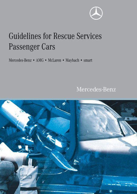
<strong>Guidelines</strong> <strong>for</strong> <strong>Rescue</strong> <strong>Services</strong><br />
<strong>Passenger</strong> <strong>Cars</strong><br />
Mercedes-Benz • AMG • McLaren • Maybach • smart
Mercedes-Benz Service<br />
<strong>Guidelines</strong> <strong>for</strong> <strong>Rescue</strong> <strong>Services</strong><br />
<strong>Passenger</strong> <strong>Cars</strong><br />
Mercedes-Benz • Maybach • McLaren • smart<br />
Daimler AG · Technical In<strong>for</strong>mation and Workshop Equipment (GSP/OI) · D-70546 Stuttgart, Germany
In<strong>for</strong>mation and copyright<br />
Ordering workshop in<strong>for</strong>mation<br />
All printed workshop in<strong>for</strong>mation from GSP/OI, such as Introduction into<br />
Service Manuals, System Descriptions, Function Descriptions, Technology<br />
Guides, Technical Data Manuals and adhesive labels, can be ordered as<br />
follows:<br />
In Germany<br />
Through our GSP/TI Shop on the internet<br />
Link: http://gsp-ti-shop.com<br />
or alternatively<br />
Email: customer.support@daimler.com<br />
Phone: +49-(0)18 05/0 10-79 79<br />
Fax: +49-(0)18 05/0 10-79 78<br />
Outside Germany<br />
Please get in touch with the contact person responsible <strong>for</strong> your market.<br />
Product Portfolio<br />
Comprehensive in<strong>for</strong>mation about our full Product Portfolio<br />
can also be found at our Internet Portal.<br />
Link: http://aftersales.mercedes-benz.com<br />
Questions and suggestions<br />
If you have any questions or suggestions concerning this product, please write<br />
to us.<br />
Email: customer.support@daimler.com<br />
Fax: +49-(0)18 05/0 10-79 78<br />
or alternatively<br />
Address: Daimler AG<br />
GSP/OIS<br />
HPC R822, W002<br />
D-70546 Stuttgart, Germany<br />
© 2010 by Daimler AG<br />
This document, including all its parts, is protected by copyright. Any further<br />
processing or use requires the previous written consent of Daimler AG, Department<br />
GSP/OIS, HPC R822, W002, D-70546 Stuttgart, Germany.<br />
This applies in particular to reproduction, distribution, alteration, translation,<br />
microfilming and storage and/or processing in electronic systems, including<br />
databases and online services.<br />
Image no. of title image: P00.01-3447-00<br />
04/10
Changes compared to 11/2009 issue<br />
! Observe modification notes<br />
<strong>Rescue</strong><br />
Modification notes<br />
Special considerations <strong>for</strong> the SLS AMG (model 197) 74<br />
Fuel cell drive system 124<br />
Mercedes-Benz model classes<br />
B-Class F-Cell (model 245) 137<br />
E-Class convertible (model 207) 152<br />
SLS AMG (model 197) 156<br />
i Note<br />
The model class overviews are also available as<br />
"rescue cards" free of charge on the internet.<br />
<strong>Rescue</strong> cards are available <strong>for</strong> all current<br />
passenger car model series as well as <strong>for</strong> predecessor<br />
model series produced in or after 1979.<br />
<strong>Guidelines</strong> <strong>for</strong> <strong>Rescue</strong> <strong>Services</strong>, <strong>Passenger</strong> <strong>Cars</strong> 2010 • Issue Date: April 2010<br />
b<br />
3
Modification notes<br />
4 b <strong>Guidelines</strong> <strong>for</strong> <strong>Rescue</strong> <strong>Services</strong>, <strong>Passenger</strong> <strong>Cars</strong> 2010 • Issue Date: April 2010
Contents<br />
Preface 9<br />
Overview<br />
Proper casualty rescue 10<br />
Extinguishing vehicle fires 11<br />
New materials 13<br />
Body 14<br />
<strong>Rescue</strong><br />
Securing and supporting 20<br />
Removing the windows 23<br />
Switching off the engine 27<br />
Central locking emergency opening 28<br />
Removing the vehicle doors •<br />
Mercedes-Benz passenger cars 29<br />
Removing the vehicle doors •<br />
Maybach 33<br />
Removing the vehicle doors •<br />
smart 36<br />
Removing the vehicle roof •<br />
Mercedes-Benz passenger cars 41<br />
Removing the vehicle roof • Maybach 51<br />
Removing the vehicle roof • smart 58<br />
Pushing away the instrument panel •<br />
Mercedes-Benz passenger cars 65<br />
Pushing away the instrument panel • Maybach 68<br />
Pushing away the instrument panel • smart 70<br />
<strong>Guidelines</strong> <strong>for</strong> <strong>Rescue</strong> <strong>Services</strong>, <strong>Passenger</strong> <strong>Cars</strong> 2010 • Issue Date: April 2010<br />
b<br />
5
Contents<br />
Special considerations <strong>for</strong><br />
the SLS AMG (model 197) 74<br />
Seat adjustment • Mercedes-Benz passenger cars 79<br />
Seat adjustment • Maybach 81<br />
Seat adjustment • smart 82<br />
Removing the head restraints •<br />
Mercedes-Benz passenger cars 83<br />
Removing the head restraints • Maybach 85<br />
Removing the head restraints • smart 86<br />
Easy entry/exit feature •<br />
Mercedes-Benz passenger cars 87<br />
Easy entry/exit feature • Maybach 89<br />
Adjusting the steering column •<br />
Mercedes-Benz passenger cars 90<br />
Adjusting the steering column • Maybach 91<br />
Adjusting the steering wheel • smart 92<br />
Roll bar • Mercedes-Benz passenger cars 93<br />
Roll bar • smart 95<br />
Occupant restraint systems •<br />
Mercedes-Benz passenger cars 96<br />
Occupant restraint systems • Maybach 105<br />
Occupant restraint systems • smart 107<br />
Bivalent engine operation 110<br />
High-voltage systems 116<br />
Hybrid concept 119<br />
6 b <strong>Guidelines</strong> <strong>for</strong> <strong>Rescue</strong> <strong>Services</strong>, <strong>Passenger</strong> <strong>Cars</strong> 2010 • Issue Date: April 2010
Contents<br />
<strong>Electric</strong> drive system 121<br />
Fuel cell drive system 124<br />
Active engine hood 130<br />
Mercedes-Benz model classes<br />
General 132<br />
Sedan 134<br />
Station wagon 144<br />
Coupé 146<br />
Cabrio 151<br />
Roadster 153<br />
Cross-country vehicle 157<br />
Van 162<br />
Maybach model overview<br />
General 165<br />
Maybach 57/62 168<br />
smart model classes<br />
General 169<br />
smart <strong>for</strong>two 171<br />
smart roadster 177<br />
smart <strong>for</strong>four 178<br />
<strong>Guidelines</strong> <strong>for</strong> <strong>Rescue</strong> <strong>Services</strong>, <strong>Passenger</strong> <strong>Cars</strong> 2010 • Issue Date: April 2010<br />
b<br />
7
Contents<br />
Integral safety<br />
Safety concept 179<br />
Annex<br />
List of abbreviations 183<br />
Index 184<br />
8 b <strong>Guidelines</strong> <strong>for</strong> <strong>Rescue</strong> <strong>Services</strong>, <strong>Passenger</strong> <strong>Cars</strong> 2010 • Issue Date: April 2010
Dear Reader,<br />
One of Daimler's main priorities has traditionally been<br />
to guarantee the highest possible standards of safety.<br />
For this reason our vehicles always represent the state<br />
of the art. And this is especially true <strong>for</strong> vehicle safety.<br />
Our safety concept is as comprehensive as possible<br />
and also extends to providing rescue crews with<br />
specific in<strong>for</strong>mation about our vehicles and their<br />
safety systems.<br />
The top priority of the rescue crew is to save lives. The<br />
rescue team must be able to gain access to the accident<br />
victims as quickly as possible without exposing<br />
them or themselves to additional danger.<br />
In order to do this, the rescue services must be properly<br />
trained. In addition, knowledge of vehicle-specific<br />
accessibility options and of the function and operation<br />
of the safety systems is absolutely essential.<br />
Mercedes-Benz has been providing this in<strong>for</strong>mation in<br />
its "<strong>Guidelines</strong> <strong>for</strong> <strong>Rescue</strong> <strong>Services</strong>" since March<br />
1994. The guidelines have been revised regularly ever<br />
since.<br />
The constant development of our vehicles, particularly<br />
in the field of vehicle safety, and the expansion of our<br />
product range have necessitated another update.<br />
<strong>Guidelines</strong> <strong>for</strong> <strong>Rescue</strong> <strong>Services</strong>, <strong>Passenger</strong> <strong>Cars</strong> 2010 • Issue Date: April 2010<br />
Preface<br />
These guidelines describe several methods <strong>for</strong><br />
rescuing accident victims from the vehicle. We must<br />
emphasize, however, that these guidelines cannot<br />
claim to be exhaustive and on no account should they,<br />
nor are they intended to, act as a substitute <strong>for</strong> proper<br />
specialist training and the relevant specialized literature.<br />
The new passenger car vehicle models have been<br />
added to these guidelines, which also include up-todate<br />
in<strong>for</strong>mation on occupant restraint systems,<br />
passive and active safety systems, new materials and<br />
alternative drive systems.<br />
For their helpful cooperation we should like to extend<br />
our warmest gratitude to our company fire brigades at<br />
the Sindelfingen, Untertürkheim and Mettingen<br />
plants, to the Stuttgart Fire Service, to our accident<br />
research department, to our development department,<br />
to our company medical services at<br />
Sindelfingen, Untertürkheim and Mettingen, and to<br />
everybody else involved.<br />
The photographs were taken while per<strong>for</strong>ming cutting<br />
tests on vehicles of various model series as well as<br />
during an exercise series "Technical assistance <strong>for</strong><br />
passenger cars, patient-suitable rescue" of the plant<br />
firefighting department at Daimler Sindelfingen,<br />
Germany.<br />
Daimler AG<br />
Technical In<strong>for</strong>mation<br />
and Workshop Equipment (GSP/OI)<br />
b<br />
9
Overview<br />
10<br />
Proper casualty rescue<br />
Whereas <strong>for</strong>merly priority was given to quickly<br />
rescuing the trapped accident victims from their<br />
predicament, the primary concern nowadays is<br />
medical and psychological assistance. The aim of this<br />
is to prepare the casualty as well as possible <strong>for</strong> the<br />
rescue work.<br />
The medical and rescue personnel can then work in<br />
concert to free the casualty from the vehicle.<br />
The most important immediate measures at<br />
the scene of accident are:<br />
• Maintaining or restoring the vital functions<br />
(respiration/circulation)<br />
• Keeping the respiratory passages clear and<br />
rectifying any breathing difficulties<br />
• Assessing shock and initiating measures to<br />
stabilize the casualty<br />
• Rendering psychological support to the casualty<br />
• Treating life-threatening injuries<br />
• Stopping major bleeding<br />
• Immobilizing certain body parts<br />
Immobilizing the neck<br />
As the head often experiences extreme movements in<br />
traffic accidents, there is an increased risk of spinal<br />
injury in the neck region. To prevent further damage to<br />
the cervical vertebrae, it is essential to immobilize the<br />
neck be<strong>for</strong>e any further rescue action is undertaken. A<br />
cervical collar ("Stifnek") is usually used <strong>for</strong> this<br />
purpose. It consists of a piece of plastic which is<br />
placed around the neck and fastened in place with a<br />
Velcro fastener.<br />
If access to the casualty is difficult, the head restraint<br />
can be removed first be<strong>for</strong>e fitting the cervical collar.<br />
i The main priority is to render medical and<br />
psychological aid to the casualty!<br />
i However, the safety of the medical and<br />
rescue crews themselves should not be<br />
neglected!<br />
• Wear protective clothing<br />
• Wear eye protection<br />
• Wear protective mouth mask<br />
• Secure the accident vehicle<br />
i Head restraints should only be removed<br />
by cutting them off in exceptional cases and in<br />
consultation with the emergency physician.<br />
• Cutting off the head restraints exposes the<br />
casualty to additional movements<br />
• The head restraint can no longer be used to<br />
stabilize the casualty's head<br />
• Cutting off the head restraints can cause sharp<br />
edges<br />
b <strong>Guidelines</strong> <strong>for</strong> <strong>Rescue</strong> <strong>Services</strong>, <strong>Passenger</strong> <strong>Cars</strong> 2010 • Issue Date: April 2010
Extinguishing vehicle fires<br />
Extinguish fires in accordance with the guidelines of the professional fire services.<br />
Body:<br />
Magnesium is increasingly being used in safety-relevant<br />
rein<strong>for</strong>cement structures in the body. Thus, e.g.<br />
the inner door panels on the S-Class coupé<br />
(model 215) and SL-Class roadster (model 230) are<br />
made of magnesium.<br />
<strong>Vehicle</strong>s with fuel cell drive:<br />
<strong>Vehicle</strong>s with a fuel cell drive (B-Class F-Cell) are<br />
equipped with hydrogen tanks. On these vehicles the<br />
guidelines on extinguishing gas fires, in particular,<br />
must be observed.<br />
<strong>Vehicle</strong>s with gasoline and natural gas drives:<br />
In the E-Class sedan (model 211) E 200 NGT and in the<br />
B-Class (model 245) B170 NGT BlueEFFICIENCY,<br />
engines are used that can be operated with either<br />
gasoline or natural gas.<br />
A comprehensive series of tests have shown that the<br />
high-strength tanks, lines, threaded connections and<br />
other equipment also provide the greatest possible<br />
safety in the event of an accident.<br />
The location of the components ensures that the<br />
natural gas does not enter the vehicle interior.<br />
The danger of fire is no greater in natural gas vehicles<br />
than in gasoline or diesel-powered vehicles.<br />
i Magnesium is a Class D flammable material<br />
according to the European "Flammable<br />
materials of various kinds" EN2 standard!<br />
i Hydrogen (H2) is a Class C flammable<br />
material according to the European "Flammable<br />
materials of various kinds" EN2 standard.<br />
i Natural gas is a Class C flammable material<br />
according to the European "Flammable<br />
materials of various kinds" EN2 standard!<br />
<strong>Guidelines</strong> <strong>for</strong> <strong>Rescue</strong> <strong>Services</strong>, <strong>Passenger</strong> <strong>Cars</strong> 2010 • Issue Date: April 2010<br />
b<br />
Overview<br />
11
Overview<br />
12<br />
Extinguishing vehicle fires<br />
Restraint systems:<br />
In the event of a fire breaking out in the vehicle interior,<br />
the front, side and head/thorax sidebag gas<br />
generators or pyrotechnical emergency tensioning<br />
retractors may be triggered.<br />
Gas generators are designed to ignite as soon as the<br />
temperature inside the gas generator reaches 160 -<br />
180 °C. In such cases the ignition squib and the solid<br />
fuel burn without destroying the gas generator. During<br />
combustion a specific volume of gas is released at a<br />
specific pressure.<br />
Windowbags<br />
The gas generators of the windowbags are filled not<br />
with solid fuel, but with compressed gas.<br />
i If the front, side and head/thorax sidebags<br />
as well as the emergency tensioning retractors<br />
are triggered the corresponding component will<br />
burn in a controlled manner and not explode.<br />
a The compressed gas generators of the windowbags<br />
must not be cut, as otherwise the compressed<br />
gas may suddenly escape!<br />
a Be<strong>for</strong>e cutting the corresponding body<br />
panels the inner paneling of the A, B or C-pillars<br />
must be removed using a suitable tool and the<br />
exact installation location of the gas generators<br />
determined!<br />
b <strong>Guidelines</strong> <strong>for</strong> <strong>Rescue</strong> <strong>Services</strong>, <strong>Passenger</strong> <strong>Cars</strong> 2010 • Issue Date: April 2010
a Risk of injury Measures<br />
Electrolyte fluid may escape if the mirror glass is<br />
broken. This fluid acts as an irritant and must not<br />
be allowed to come into contact with the skin, eyes<br />
or respiratory organs.<br />
Automatic dimming mirror:<br />
On the following vehicles the interior and exterior mirrors<br />
contain an electrolyte fluid <strong>for</strong> the automatic dimming<br />
function:<br />
• C-Class (model 204)<br />
• E-Class coupé (model 207)<br />
• CLK-Class (model 209)<br />
• E-Class (model 211)<br />
• E-Class (model 212)<br />
• CLS-Class (model 219)<br />
• S-Class (model 221)<br />
• CL-Class (model 216)<br />
• SL-Class (model 230)<br />
• Maybach (model 240)<br />
<strong>Vehicle</strong>s of other model series may also be fitted with<br />
automatic dimming mirrors as special equipment (SA).<br />
New materials<br />
If it comes into contact with the skin or eyes, immediately<br />
rinse off the fluid with generous amount<br />
of clean water. Seek medical attention if necessary.<br />
<strong>Guidelines</strong> <strong>for</strong> <strong>Rescue</strong> <strong>Services</strong>, <strong>Passenger</strong> <strong>Cars</strong> 2010 • Issue Date: April 2010<br />
P68.40-2128-00<br />
b<br />
Overview<br />
13
Overview<br />
14<br />
Body<br />
Mercedes-Benz bodyshell<br />
Materials overview, example shows CL-Class<br />
(model 216):<br />
A Low-carbon steels<br />
B High-strength steels<br />
C Modern high-strength steels<br />
D Ultrahigh-strength steel, hot worked<br />
(e.g. Usibor)<br />
E Aluminum<br />
F Plastic<br />
G Die-cast magnesium<br />
CL-Class bodyshell (model 216)<br />
The type and percentage content of the respective<br />
materials in a particular vehicle depends on the<br />
model series.<br />
Structural rein<strong>for</strong>cements in the A-pillars and Bpillars<br />
are predominantly installed in coupés,<br />
convertibles and roadsters because these parts<br />
must be particularly strong on these types of vehicles.<br />
b <strong>Guidelines</strong> <strong>for</strong> <strong>Rescue</strong> <strong>Services</strong>, <strong>Passenger</strong> <strong>Cars</strong> 2010 • Issue Date: April 2010<br />
P60.00-2751-00
Maybach bodyshell<br />
The Maybach is a large vehicle which is designed to<br />
be very com<strong>for</strong>table. The bodyshell of the Maybach<br />
must there<strong>for</strong>e fulfill particularly tough requirements<br />
in terms of rigidity, strength, acoustics and<br />
vibrational characteristics. For this reason, the<br />
bodyshell technology used in the Maybach is<br />
different to that used in the current Mercedes-Benz<br />
passenger car model series in a number of aspects<br />
e.g. more increased-strength steel is used.<br />
The following bodyshell components are made of<br />
aluminum to reduce the weight of the vehicle:<br />
• Roof<br />
• Front fenders<br />
• Engine hood<br />
• Doors<br />
The spare tire well and trunk lid are made of plastic.<br />
Bodyshell of Maybach 62 with partition wall (model 240)<br />
<strong>Guidelines</strong> <strong>for</strong> <strong>Rescue</strong> <strong>Services</strong>, <strong>Passenger</strong> <strong>Cars</strong> 2010 • Issue Date: April 2010<br />
Body<br />
The proportions of the materials used are listed<br />
below:<br />
Bodyshell material Proportion<br />
%<br />
Normal deep-drawn panel 39.5<br />
Increased-strength sheet steel 37.8<br />
Aluminum and<br />
aluminum alloys<br />
17.0<br />
Plastics 13.2<br />
Other materials 12.5<br />
P61.00-2052-00<br />
b<br />
Overview<br />
15
Overview<br />
16<br />
Body<br />
Bodyshell of SLR McLaren and SLR McLaren roadster<br />
Body<br />
The vehicle structure of the SLR consists of four<br />
main sections:<br />
• Front crash structure (1)<br />
• Front frame (2)<br />
• Monocoque (3)<br />
• Luggage compartment cell (4)<br />
<strong>Vehicle</strong> structure <strong>for</strong> SLR McLaren (model 199)<br />
The bodyshell, with the exception of the front<br />
frame, and the doors and hoods of the SLR are<br />
made of corrosion-resistant carbon fiber<br />
composite material.<br />
<strong>Vehicle</strong> structure <strong>for</strong> SLR McLaren roadster (model 199) with rein<strong>for</strong>ced A-pillars (A)<br />
In the SLR McLaren roadster, the A-pillars are rein<strong>for</strong>ced<br />
with a pipe made of high-strength steel.<br />
b <strong>Guidelines</strong> <strong>for</strong> <strong>Rescue</strong> <strong>Services</strong>, <strong>Passenger</strong> <strong>Cars</strong> 2010 • Issue Date: April 2010<br />
P60.00-2304-00<br />
P60.00-2815-00
Front crash structure<br />
The front crash structure made of carbon fiber<br />
composite material is bolted to the front frame<br />
using the two tubular energy absorption elements.<br />
The crash absorbers are designed such that they<br />
convert impact energy through the continuous<br />
breakdown of the fiber composite structure from<br />
the front to the rear into smaller particulate matter,<br />
thereby causing a controlled, mostly constant<br />
deceleration.<br />
Monocoque<br />
The passenger compartment and the fuel tank are<br />
surrounded by a safety cell (monocoque). This<br />
safety cell is made of carbon fiber composite material.<br />
The monocoque consist of several components:<br />
• Hull with integrated engine-transmission-tunnel<br />
• Differential supporting frame<br />
• Door sill<br />
• Single-piece soft top frame with roll-over<br />
protection<br />
i Note<br />
On the strength of past experience, vehicle structures<br />
made of carbon fiber composite material can<br />
be separated or de<strong>for</strong>med using the usual rescue<br />
equipment. The pendulum jigsaw is ideally suited<br />
<strong>for</strong> cutting carbon fiber parts.<br />
Front frame<br />
<strong>Guidelines</strong> <strong>for</strong> <strong>Rescue</strong> <strong>Services</strong>, <strong>Passenger</strong> <strong>Cars</strong> 2010 • Issue Date: April 2010<br />
Body<br />
The front frame is made of two separate highstrength<br />
aluminum box sections, bolted at the left<br />
and right to the monocoque, to which the engine is<br />
mounted.<br />
The following components are also mounted onto<br />
the front frame next along with the engine:<br />
• Radiator<br />
• Front suspension<br />
• Stabilizer<br />
• Exhaust muffler<br />
• Steering<br />
• Front crash structure<br />
Luggage compartment cell<br />
As with the front frame, the luggage compartment<br />
cell is also bolted to the monocoque. The rear area<br />
contains the following components:<br />
• Battery mounting<br />
• Interior ventilation<br />
• Cooler <strong>for</strong> differential<br />
• Trunk<br />
• Rear suspension<br />
The luggage compartment cell has been designed<br />
such that in the event of any rear end collision, the<br />
acting energy is then mainly absorbed.<br />
b<br />
Overview<br />
17
Overview<br />
18<br />
Body<br />
smart bodyshell<br />
Materials overview, example shows smart <strong>for</strong>two<br />
(model 451)<br />
The bodyshell structure of the new model series<br />
451 exhibits the following features:<br />
• Tridion safety cell with high-strength steels<br />
• Light alloy detachable parts<br />
• Front CMS (Crash Management System)<br />
• Rear CMS<br />
• Pedestrian protection<br />
smart <strong>for</strong>two coupé (model 451)<br />
Silver areas:<br />
The silver areas consist of soft deep-drawing steel<br />
of normal strength.<br />
Red areas:<br />
The red areas consist of micro-alloyed highstrength<br />
steels.<br />
b <strong>Guidelines</strong> <strong>for</strong> <strong>Rescue</strong> <strong>Services</strong>, <strong>Passenger</strong> <strong>Cars</strong> 2010 • Issue Date: April 2010<br />
P60.20-2063-00
smart bodyshell<br />
Green areas (cabriolet only):<br />
The green area consists of a martensite-phase<br />
steel, which is particularly high-strength and<br />
torsionally stiff.<br />
This steel is only installed on the cabriolet in the<br />
window columns of the A-pillars.<br />
smart <strong>for</strong>two cabrio (model 451)<br />
<strong>Guidelines</strong> <strong>for</strong> <strong>Rescue</strong> <strong>Services</strong>, <strong>Passenger</strong> <strong>Cars</strong> 2010 • Issue Date: April 2010<br />
Body<br />
P60.20-2064-00<br />
b<br />
Overview<br />
19
<strong>Rescue</strong><br />
20<br />
Securing and supporting<br />
a Risk of injury<br />
Unintended movements of the bodywork during<br />
rescue operations may cause further injury to the<br />
accident victims.<br />
On arrival at the scene of the accident, the first priority<br />
of the rescue crew should be to ascertain and assess<br />
the condition of the casualties.<br />
If possible, proper rescue of the occupants should<br />
only be undertaken when the vehicle has been sufficiently<br />
secured and, if possible, in consultation with<br />
the emergency physician (does not apply to emergency<br />
crash rescue!)<br />
Trapped casualties are in direct physical contact with<br />
the accident vehicle. There<strong>for</strong>e the supports must<br />
guarantee that the vehicle cannot move during the<br />
subsequent rescue operations. The vehicle can be<br />
lifted using a spreader to create sufficient space <strong>for</strong><br />
underfloor sliding blocks or wooden blocks.<br />
The support must remain secure throughout the entire<br />
duration of the rescue operation and must be able to<br />
withstand the use of hydraulic equipment.<br />
The tires should not be punctured nor should the air be<br />
let out through the valves to preserve evidence that<br />
the police may need to investigate the accident.<br />
b<br />
Measures<br />
To prevent dangerous movements from occurring<br />
while rescuing the victims, the vehicles<br />
involved should first be secured.<br />
Lifting vehicle with spreader<br />
Supporting vehicle on wooden blocks<br />
<strong>Guidelines</strong> <strong>for</strong> <strong>Rescue</strong> <strong>Services</strong>, <strong>Passenger</strong> <strong>Cars</strong> 2010 • Issue Date: February 2010<br />
P00.60-2067-00<br />
P0060-2068-00
e.g.<br />
i The actions per<strong>for</strong>med to secure the vehicle<br />
(supporting it on wooden blocks, underfloor<br />
sliding blocks or similar objects, securing it with<br />
ropes, STAB FAST or endless slings) must enable<br />
the casualties to be rescued smoothly and<br />
safely.<br />
When positioning the underfloor sliding blocks,<br />
care must be taken to ensure that the following<br />
rescue measures are not impaired.<br />
<strong>Vehicle</strong>s lying on their side must be secured to prevent<br />
them from sliding and tipping over e.g. using sectional<br />
ladders, wheel chocks, ropes and straps.<br />
•Secure vehicle using sectional ladders<br />
•Attach straps by looping them around vehicle parts,<br />
such as axles or other securely bolted or welded<br />
parts on the vehicle.<br />
•Attach steel cable to strap and tighten using pulling<br />
unit (grip puller) or cable winch<br />
•Secure opposite vehicle side using wheel chocks<br />
Securing and supporting<br />
P00.60-2083-00<br />
Supporting vehicle with underfloor sliding blocks<br />
Securing and supporting<br />
P00.60-2048-00<br />
P00.60-2086-00<br />
<strong>Guidelines</strong> <strong>for</strong> <strong>Rescue</strong> <strong>Services</strong>, <strong>Passenger</strong> <strong>Cars</strong> 2010 • Issue Date: February 2010 b<br />
<strong>Rescue</strong><br />
21
<strong>Rescue</strong><br />
22<br />
Securing and supporting<br />
<strong>Passenger</strong> car support systems are available as an<br />
alternative, with which vehicles can still be stabilized<br />
even when in complicated positions.<br />
Endless sling<br />
If the vehicle is on sloping ground, an endless sling is<br />
useful <strong>for</strong> securing the vehicle. It can also be used <strong>for</strong><br />
recovering the vehicle.<br />
The endless sling should be attached in one of the<br />
following ways:<br />
• Guide it through window openings (including when<br />
windows have been removed)<br />
• Wrap it around vehicle parts such as axles or firmly<br />
bolted/welded vehicle parts<br />
Care should be taken to pass the sling around a<br />
number of components if possible, in order to<br />
distribute the <strong>for</strong>ces evenly.<br />
b<br />
<strong>Passenger</strong> car support system (example)<br />
<strong>Guidelines</strong> <strong>for</strong> <strong>Rescue</strong> <strong>Services</strong>, <strong>Passenger</strong> <strong>Cars</strong> 2010 • Issue Date: February 2010<br />
P00.60-2081-00<br />
P00.60-2008-00
a Risk of injury Measures<br />
Work on windows and glass roofs may produce<br />
glass splinters which can cause injuries to the<br />
occupants and rescuers.<br />
a Risk of injury Measures<br />
Always remove the windows when working on<br />
adjacent components.<br />
Windows may shatter resulting in tiny, sharp<br />
glass particles flying around which may cause<br />
injury to the occupants and rescuers.<br />
Windows in parts adjacent to those being worked on<br />
must always be removed be<strong>for</strong>e using hydraulic tools.<br />
This applies above all to the windows in the doors. If<br />
the windows are not removed, then when opening the<br />
doors using the spreader together with the corresponding<br />
body panels, they can be subjected to enormous<br />
pressure.<br />
At a certain compressive <strong>for</strong>ce the windows will be<br />
unable to withstand the pressure and will burst<br />
suddenly and violently. The ejected fragments can<br />
inflict injuries.<br />
Removing the windows<br />
Cover the occupants be<strong>for</strong>e commencing work,<br />
preferably with a transparent sheet.<br />
Wear protective clothing and gloves and safety<br />
glasses.<br />
Cover the occupants be<strong>for</strong>e commencing work,<br />
preferably with a transparent sheet.<br />
Wear protective clothing and gloves and safety<br />
glasses.<br />
<strong>Vehicle</strong>s in the Mercedes-Benz passenger car model<br />
series and smart model series are generally equipped<br />
with two types of safety glass.<br />
The windshield and door windows are made of laminated<br />
safety glass (VSG), the rear and side windows<br />
on almost all vehicles are made of single-pane safety<br />
glass (ESG).<br />
All of the windows on the Maybach (model 240) are<br />
made of laminated safety glass (VSG).<br />
<strong>Guidelines</strong> <strong>for</strong> <strong>Rescue</strong> <strong>Services</strong>, <strong>Passenger</strong> <strong>Cars</strong> 2010 • Issue Date: February 2010 b<br />
<strong>Rescue</strong><br />
23
<strong>Rescue</strong><br />
24<br />
Removing the windows<br />
Removing windows using a glass saw<br />
The glass saw is usually chosen to remove windows<br />
made of laminated safety glass (VSG).<br />
• First knock a hole in the bottom of the window<br />
• Then saw out the window at the bottom along the<br />
door<br />
With a glass saw, the actual cutting occurs on the pull<br />
stroke and not on the push stroke as with conventional<br />
saws. The advantage of this is that the casualty<br />
inside the vehicle is less exposed to the glass particles<br />
produced.<br />
• Press the window outwards and pull out of the<br />
guide rails<br />
A pendulum jigsaw can be used as an alternative <strong>for</strong><br />
removing laminated safety glass windows.<br />
Here one should note that when sawing, fine-grained<br />
glass dust is created. For this reason be<strong>for</strong>e<br />
commencing the sawing process safety precautions<br />
must be taken:<br />
• The occupants should be covered preferably with a<br />
transparent sheet<br />
• The rescue personnel should also wear a mask<br />
and safety glasses in addition to the helmet visor<br />
b<br />
<strong>Guidelines</strong> <strong>for</strong> <strong>Rescue</strong> <strong>Services</strong>, <strong>Passenger</strong> <strong>Cars</strong> 2010 • Issue Date: February 2010<br />
P67.00-2036-00<br />
P67.30-2244-00<br />
P67.00-2041-00
Removing windows using a spring punch<br />
The side windows on almost all vehicles (except<br />
Maybach) are made of single-pane safety glass (ESG)<br />
and can be removed using a spring center punch:<br />
• Stick adhesive foil or tape over the window<br />
• Position the spring center punch in one of the<br />
bottom corners<br />
• Punch the window with the spring center punch<br />
• The window shatters into small shards which stick<br />
to the film or adhesive tape.<br />
• Remove the window outwards<br />
• Remove remaining fragments of glass from the<br />
window frame (remove the rubber edge strip)<br />
Glass roof on smart <strong>for</strong>four (model 454)<br />
• Stick adhesive foil or tape over the window<br />
• Knock a hole in one of the corners of the glass roof<br />
• Cut out the window along the edge of the opening<br />
in the roof using a glass saw<br />
• Remove the window outwards<br />
Both the glass roof and the plastic roof are adhesivebonded<br />
to the body structure.<br />
Removing the windows<br />
P67.30-2241-00<br />
P67.30-2242-00<br />
P65.10-3215-00<br />
<strong>Guidelines</strong> <strong>for</strong> <strong>Rescue</strong> <strong>Services</strong>, <strong>Passenger</strong> <strong>Cars</strong> 2010 • Issue Date: February 2010 b<br />
<strong>Rescue</strong><br />
25
<strong>Rescue</strong><br />
26<br />
Removing the windows<br />
Side window on smart <strong>for</strong>two (model 450)<br />
The panes of the quarter windows behind the B-pillars<br />
on the smart <strong>for</strong>two (model 450) are manufactured<br />
from breakproof plastic (polycarbonate) and are held<br />
in place by clips. They can be pried out using a suitable<br />
tool, such as a crowbar or Halligan tool.<br />
Removing windows with a Halligan tool:<br />
Laminated glass windows can be quickly and easily<br />
removed using a Halligan tool:<br />
• First knock a hole in the window<br />
• Then rip out the window using the tool.<br />
i Be<strong>for</strong>e windows are sawn or opened with<br />
special removal tools, the occupants must be<br />
covered, preferably with a transparent sheet, to<br />
prevent any potential risk of injury.<br />
<strong>Rescue</strong> personnel must wear protective<br />
clothing, safety glasses and protective mouth<br />
masks in addition to their helmet visor!<br />
b<br />
Halligan tool<br />
<strong>Guidelines</strong> <strong>for</strong> <strong>Rescue</strong> <strong>Services</strong>, <strong>Passenger</strong> <strong>Cars</strong> 2010 • Issue Date: February 2010<br />
P67.00-2040-00<br />
P67.00-2046-00<br />
P67.00-2047-00
Switching off the engine on vehicles with automatic transmission<br />
Switch off engine by turning the ignition key counterclockwise<br />
to the "0" position and then remove the ignition<br />
key.<br />
Switching off the engine on vehicles with KEYLESS-GO<br />
KEYLESS-GO is a keyless access and drive authorization<br />
system.<br />
In some accident situations the engine may continue<br />
to operate after a crash. If the vehicle key is not in the<br />
ignition switch in vehicles with KEYLESS GO, the<br />
engine can be switched off as follows:<br />
• Move the selector lever to position "P" or "N"<br />
• Press START/STOP button (1) on selector lever<br />
once<br />
Switching off the engine<br />
i On vehicles with automatic transmission,<br />
the ignition key can only be removed if the<br />
selector lever is in position "P".<br />
P80.61-2033-00<br />
<strong>Guidelines</strong> <strong>for</strong> <strong>Rescue</strong> <strong>Services</strong>, <strong>Passenger</strong> <strong>Cars</strong> 2010 • Issue Date: February 2010 b<br />
<strong>Rescue</strong><br />
27
<strong>Rescue</strong><br />
28<br />
Central locking emergency opening<br />
Automatic unlocking of the central locking in the event of an accident<br />
Mercedes-Benz and Maybach vehicles are equipped<br />
with the "Central locking emergency opening"<br />
function in the event of a crash.<br />
Installed in a separate control unit is an additional<br />
crash sensor. At a defined vehicle acceleration the<br />
signal <strong>for</strong> emergency opening is transmitted after a<br />
specific waiting time to the door control units. The<br />
doors are then unlocked by the respective door<br />
control unit.<br />
Hazard warning system<br />
In the event of a crash, the hazard warning system is<br />
automatically switched on, depending on the vehicle<br />
model.<br />
It can be switched off again at any time using the hazard<br />
warning flasher switch.<br />
Generally, the hazard warning system is used to show<br />
the rescue team that the vehicle voltage supply is<br />
operational.<br />
The hazard warning system is not deactivated until the<br />
battery/batteries is/are disconnected. This shows<br />
that the vehicle is free of electric current.<br />
b<br />
P54.25-4401-00<br />
C-Class hazard warning flasher switch (model 204)<br />
<strong>Guidelines</strong> <strong>for</strong> <strong>Rescue</strong> <strong>Services</strong>, <strong>Passenger</strong> <strong>Cars</strong> 2010 • Issue Date: February 2010
Removing the vehicle doors • Mercedes-Benz passenger cars<br />
First check whether the door catch can be opened in<br />
spite of the de<strong>for</strong>med door.<br />
It may be possible to open the door enough to allow<br />
the spreader to be pushed into the resulting gap. If the<br />
lock cannot be opened, the following procedure is<br />
recommended:<br />
Opening on the lock side:<br />
• Remove side windows made of single-pane safety<br />
glass<br />
• Push one tip of the spreader into the door gap (at<br />
about the height of the door lock) on the B-pillar<br />
• Grip the door fold with the spreader and bend<br />
outwards<br />
• Press both tips of the spreader into the opening<br />
produced, in order to expand the opening in a<br />
number of small spreading operations. During this<br />
process slide the ends of the spreader toward the<br />
door lock, continuing until the door pops open.<br />
Alternative procedure<br />
• Remove side window made of single-pane safety<br />
glass<br />
• Insert spreader between door and upper window<br />
frame<br />
• Open spreader<br />
• Bend upper window frame outwards using<br />
spreader<br />
i Do not use excessive <strong>for</strong>ce to ram the<br />
spreader into the door gap, in order to avoid<br />
any unintended movement of the car body.<br />
Proceed carefully with the patient in mind.<br />
P72.00-2176-00<br />
P72.00-2132-00<br />
<strong>Guidelines</strong> <strong>for</strong> <strong>Rescue</strong> <strong>Services</strong>, <strong>Passenger</strong> <strong>Cars</strong> 2010 • Issue Date: February 2010 b<br />
<strong>Rescue</strong><br />
29
<strong>Rescue</strong><br />
30<br />
Removing the vehicle doors • Mercedes-Benz passenger cars<br />
• Enlarge the resulting opening from above using the<br />
spreader until the door pops open<br />
The inside door handle <strong>for</strong> the door lock release mechanism<br />
can be held open using a wooden wedge to<br />
facilitate opening.<br />
• Open the door all the way<br />
• Spread open and rip off the hinges using the<br />
spreader<br />
b<br />
<strong>Guidelines</strong> <strong>for</strong> <strong>Rescue</strong> <strong>Services</strong>, <strong>Passenger</strong> <strong>Cars</strong> 2010 • Issue Date: February 2010<br />
P72.10-3485-00<br />
P72.10-3486-00<br />
P72.10-3487-00
Removing the vehicle doors • Mercedes-Benz passenger cars<br />
• Cut the electrical lines<br />
• Remove the door<br />
Opening on the hinge side:<br />
• Squeeze the front fender with the spreader to<br />
enlarge the door gap on the hinge side. Ensure that<br />
the spreader does not touch the suspension strut.<br />
This procedure cannot be used on fenders made of<br />
plastic.<br />
Where plastic fenders are involved or where the accident<br />
has closed off access proceed as follows:<br />
• Remove side window<br />
• Insert spreader between door and upper door<br />
frame<br />
• Expand spreader until a sufficient gap <strong>for</strong>ms at the<br />
hinge side of the door<br />
P72.10-3488-00<br />
P72.00-2058-00<br />
<strong>Guidelines</strong> <strong>for</strong> <strong>Rescue</strong> <strong>Services</strong>, <strong>Passenger</strong> <strong>Cars</strong> 2010 • Issue Date: February 2010 b<br />
<strong>Rescue</strong><br />
31
<strong>Rescue</strong><br />
32<br />
Removing the vehicle doors • Mercedes-Benz passenger cars<br />
Opening on the hinge side:<br />
The following procedure can also be used:<br />
• Remove side window<br />
• Apply spreader at an incline from above<br />
• Squeeze door using spreader until a sufficient gap<br />
<strong>for</strong>ms at the hinge side of the door<br />
• Further enlarge the door gap at the height of the<br />
door lock using a spreader<br />
• Spread open and rip off the hinges using the<br />
spreader<br />
• Cut the electrical lines<br />
• Remove the door<br />
i The hinge pins are hardened. Hardened<br />
parts cannot be cut. There is a risk that the<br />
cutting blade on the hydraulic cutting gear<br />
may be damaged or destroyed.<br />
b<br />
<strong>Guidelines</strong> <strong>for</strong> <strong>Rescue</strong> <strong>Services</strong>, <strong>Passenger</strong> <strong>Cars</strong> 2010 • Issue Date: February 2010<br />
P72.00-2133-00<br />
P72.00-2054-00
Opening on the hinge side:<br />
• Remove the side windows<br />
• To create the required gap, squeeze/remove the<br />
fender with the spreader or<br />
• create the required gap using a Halligan tool<br />
• Spread open and rip off the hinges using the<br />
spreader. The hinges break at the pins.<br />
• Cut the electrical lines<br />
• Remove the door<br />
Opening the front door<br />
Removing the vehicle doors • Maybach<br />
P72.00-2165-00<br />
Opening the rear door<br />
P72.00-2164-00<br />
P72.00-2166-00<br />
<strong>Guidelines</strong> <strong>for</strong> <strong>Rescue</strong> <strong>Services</strong>, <strong>Passenger</strong> <strong>Cars</strong> 2010 • Issue Date: February 2010 b<br />
<strong>Rescue</strong><br />
33
<strong>Rescue</strong><br />
34<br />
Removing the vehicle doors • Maybach<br />
Opening the front doors at the lock side<br />
• Remove side window<br />
• Apply spreader vertically from above<br />
• Squeeze door until a sufficient gap has <strong>for</strong>med at<br />
the hinge side<br />
• Alternatively, insert spreader between door and<br />
upper door frame<br />
• Expand spreader until a sufficient gap <strong>for</strong>ms at the<br />
lock side of the door<br />
• Press both tips of the spreader into the opening<br />
produced, in order to expand the opening in a<br />
number of small spreading operations. During this<br />
process slide the ends of the spreader toward the<br />
door lock, continuing until the door pops open.<br />
• Spread open and rip off the hinges using the<br />
spreader<br />
• Cut the electrical lines<br />
• Remove the door<br />
b<br />
<strong>Guidelines</strong> <strong>for</strong> <strong>Rescue</strong> <strong>Services</strong>, <strong>Passenger</strong> <strong>Cars</strong> 2010 • Issue Date: February 2010<br />
P72.00-2167-00<br />
P72.10-3489-00<br />
P72.00-2168-00
Opening the rear doors at the lock side<br />
• Remove the side windows<br />
• Insert spreader in window frame at an angle<br />
i Note<br />
With any other procedure, only the aluminum door<br />
paneling is stripped off without a sufficiently large<br />
opening being created in the area of the door lock.<br />
• Expand spreader until a sufficient gap has <strong>for</strong>med<br />
• Press both tips of the spreader into the opening<br />
produced from above in order to expand the<br />
opening in a number of small spreading operations.<br />
During this process slide the ends of the spreader<br />
toward the door lock, continuing until the door<br />
pops open.<br />
• Cut off the hinges using the rescue shears or<br />
spread them with the spreader until they break off<br />
• Cut the electrical lines<br />
• Remove the door<br />
i The hinge pins are hardened. Hardened<br />
parts cannot be cut. There is a risk that the<br />
cutting blade on the hydraulic cutting gear<br />
may be damaged or destroyed.<br />
Removing the vehicle doors • Maybach<br />
P72.00-2169-00<br />
P72.00-2170-00<br />
P72.00-2171-00<br />
<strong>Guidelines</strong> <strong>for</strong> <strong>Rescue</strong> <strong>Services</strong>, <strong>Passenger</strong> <strong>Cars</strong> 2010 • Issue Date: February 2010 b<br />
<strong>Rescue</strong><br />
35
<strong>Rescue</strong><br />
36<br />
Removing the vehicle doors • smart<br />
smart <strong>for</strong>two (model 450, model 451) and smart roadster (model 452)<br />
Opening on the lock side<br />
• Secure vehicle and support on blocks<br />
• The plastic door paneling can be removed to<br />
provide a better overview of the location of the<br />
hinges and door lock<br />
• Use a crowbar to create a gap large enough to<br />
insert the rescue shears<br />
• Insert the rescue shears and cut through the<br />
striker of the door lock<br />
b<br />
Striker after being cut off<br />
<strong>Guidelines</strong> <strong>for</strong> <strong>Rescue</strong> <strong>Services</strong>, <strong>Passenger</strong> <strong>Cars</strong> 2010 • Issue Date: February 2010<br />
P72.00-2116-00<br />
P72.00-2115-00<br />
P72.00-2114-00
Removing the vehicle doors • smart<br />
smart <strong>for</strong>two (model 450, model 451) and smart roadster (model 452)<br />
• Open the door all the way<br />
• Insert spreader at upper hinge<br />
• Spread open and rip off the hinge using the<br />
spreader<br />
• Insert spreader at lower hinge<br />
• Spread open and rip off the hinge using the<br />
spreader<br />
• Cut the electrical lines<br />
• Remove the door<br />
P72.10-3501-00<br />
P72.00-3500-00<br />
<strong>Guidelines</strong> <strong>for</strong> <strong>Rescue</strong> <strong>Services</strong>, <strong>Passenger</strong> <strong>Cars</strong> 2010 • Issue Date: February 2010 b<br />
<strong>Rescue</strong><br />
37
<strong>Rescue</strong><br />
38<br />
Removing the vehicle doors • smart<br />
smart <strong>for</strong>two (model 450, model 451) and smart roadster (model 452)<br />
Because the hinges are made of <strong>for</strong>ged steel, and thus<br />
extremely strong, the recommended procedure on the<br />
smart <strong>for</strong>two (model 450) is to open the door on the<br />
lock side, where the spreader can act against the<br />
more pliant aluminum of the door structure.<br />
Opening on the hinge side<br />
On the new smart <strong>for</strong>two (model 451), the door structure<br />
is made of steel. In addition, high-strength sheet<br />
steel and steel profile is used <strong>for</strong> the diagonal strut<br />
and the strips <strong>for</strong> the side window channels. This<br />
makes opening at the hinge side easier on this vehicle.<br />
• The plastic door paneling can be removed to<br />
provide a better overview of the location of the<br />
hinges and door lock<br />
• Remove plastic fender<br />
• Insert spreader at hinge<br />
• Spread open and rip off the hinges using the<br />
spreader<br />
• Cut the electrical lines<br />
• Remove the door<br />
b<br />
Should it be absolutely necessary to open the door on<br />
the hinge side, apply the spreader at the upper hinge,<br />
inserting it from above. Hold the spreader vertically<br />
and rip off the hinge<br />
<strong>Guidelines</strong> <strong>for</strong> <strong>Rescue</strong> <strong>Services</strong>, <strong>Passenger</strong> <strong>Cars</strong> 2010 • Issue Date: February 2010<br />
P72.00-2179-00<br />
P72.00-2180-00
smart <strong>for</strong>four (model 454)<br />
Opening on the hinge side<br />
• Remove plastic door paneling<br />
• Position the spreader between the hinge and the Apillar<br />
or fender<br />
• Spread the hinge until it breaks off<br />
The following procedure can also be used:<br />
• Remove plastic door paneling<br />
• Cut through door frame (1) above hinges using the<br />
rescue shears (cut A)<br />
• Cut through door frame (1) below hinges using the<br />
rescue shears (cut B)<br />
• Cut through the window frame (2)<br />
Removing the vehicle doors • smart<br />
1 Door frame<br />
2 Window frame<br />
P72.00-2156-00<br />
P72.00-2157-00<br />
P72.00-2158-00<br />
<strong>Guidelines</strong> <strong>for</strong> <strong>Rescue</strong> <strong>Services</strong>, <strong>Passenger</strong> <strong>Cars</strong> 2010 • Issue Date: February 2010 b<br />
<strong>Rescue</strong><br />
39
<strong>Rescue</strong><br />
40<br />
Removing the vehicle doors • smart<br />
smart <strong>for</strong>four (model 454)<br />
• Cut through the crossmember (3) (cut C)<br />
• Cut the electrical lines<br />
• Insert the spreader from above and pull the door<br />
outwards<br />
• Carefully cover sharp-edged parts using a set of<br />
protective covers<br />
b<br />
3 Crossmember<br />
<strong>Guidelines</strong> <strong>for</strong> <strong>Rescue</strong> <strong>Services</strong>, <strong>Passenger</strong> <strong>Cars</strong> 2010 • Issue Date: February 2010<br />
P72.00-2159-00<br />
P72.00-2160-00<br />
P72.00-2161-00
Removing the vehicle roof • Mercedes-Benz passenger cars<br />
a Risk of injury Measures<br />
When vehicle parts are cut open or cut off the<br />
vehicle, this produces sharp interfaces with the<br />
potential to cause injury to both rescue personnel<br />
and the accident victims within the vehicle.<br />
a Risk of injury Measures<br />
The gas generators <strong>for</strong> the windowbags are filled<br />
with compressed gas and there<strong>for</strong>e they should<br />
not be cut, if possible. Suitable safety precautions<br />
<strong>for</strong> patients and the rescue team should be implemented,<br />
if required.<br />
The bursting of a gas generator may lead to sharpedge<br />
parts being ejected at high speeds.<br />
The loud noise may result in the victims experiencing<br />
a blast trauma.<br />
The roof plays a major role in lending rigidity to the<br />
body. When cutting away the roof, it is absolutely<br />
essential to ensure that the vehicle is adequately and<br />
safely supported so as to prevent the body from<br />
collapsing and causing further injury to the occupants.<br />
Furthermore, important fixed points on the bodywork,<br />
which may be necessary later in the rescue of the<br />
victims, could be destabilized or destroyed by cutting<br />
away the roof.<br />
Removing the vehicle roof must there<strong>for</strong>e be considered<br />
a critically important event and should be<br />
planned with the emergency physician. If removing the<br />
roof is the only possible way of gaining access to the<br />
victim or of initiating other essential action, carefully<br />
consider whether partial removal of the roof might be<br />
sufficient.<br />
Depending on the accident situation, the corresponding<br />
pillar can be folded <strong>for</strong>ward or backwards<br />
after being cut.<br />
Cover the appropriate parts with protective<br />
covers or pillar protection.<br />
Remove inner paneling of A, B and C-pillars<br />
using a suitable tool and check whether any gas<br />
generators are installed in the area of the<br />
planned cuts. Mark the position of the cuts on<br />
the outside of the vehicle.<br />
Set of protective covers (example)<br />
1 Pillar padding with Velcro fastener<br />
2 Protective cover with round magnets<br />
P62.00-2097-00<br />
<strong>Guidelines</strong> <strong>for</strong> <strong>Rescue</strong> <strong>Services</strong>, <strong>Passenger</strong> <strong>Cars</strong> 2010 • Issue Date: February 2010 b<br />
<strong>Rescue</strong><br />
41
<strong>Rescue</strong><br />
42<br />
Removing the vehicle roof • Mercedes-Benz passenger cars<br />
Partial removal of roof<br />
• Saw out windshield at edges (see chapter:<br />
Removing the windows)<br />
• Remove inner paneling of A-pillar and check<br />
whether a gas generator has been installed in<br />
the A-pillar <strong>for</strong> the windowbag. Mark cutting<br />
position on outside of vehicle<br />
• Cut through the A-pillar as close to the bottom as<br />
possible but do not cut the gas generator!<br />
• On the CL-Class (model 216) and the E-Class<br />
coupé (model 207), the A-pillars are rein<strong>for</strong>ced by<br />
a high-strength steel tube. These internal<br />
rein<strong>for</strong>cement tubes can only but cut using highpowered<br />
rescue shears and they must be exposed<br />
first.<br />
• It is easier to cut the A-pillar free in the area of the<br />
roof frame on this vehicle.<br />
• On the S-Class (model 221) the cutting points are<br />
marked (> CUT
Removing the vehicle roof • Mercedes-Benz passenger cars<br />
Partial removal of roof<br />
• Remove inner paneling of B-pillars and<br />
determine location of seat belt height adjuster or<br />
any structural rein<strong>for</strong>cements present<br />
• Check whether a gas generator <strong>for</strong> the<br />
windowbag is installed above the B-pillar in the<br />
roof frame. Mark cutting position on outside of<br />
vehicle<br />
• Cut through B-pillar above the seat belt height<br />
adjuster<br />
• On vehicles with a structurally rein<strong>for</strong>ced B-pillar,<br />
e.g. E-Class (model 211); C-Class (model 204) and<br />
CLK-Class coupés (model 209), cut off the B-pillar<br />
by making a v-shaped cut through the roof at the<br />
sides but do not cut the gas generator!<br />
• Saw open the rear window at the top between the<br />
C-pillars<br />
• Remove inner paneling of C-pillar and check<br />
whether a gas generator has been installed in<br />
the C-pillar <strong>for</strong> the windowbag. Mark cutting<br />
position on outside of vehicle<br />
• Make a v-shaped cut at the top of the C-pillar but<br />
do not cut the gas generator!<br />
P62.00-2086-00<br />
P62.00-2075-00<br />
P63.20-5674-00<br />
<strong>Guidelines</strong> <strong>for</strong> <strong>Rescue</strong> <strong>Services</strong>, <strong>Passenger</strong> <strong>Cars</strong> 2010 • Issue Date: February 2010 b<br />
<strong>Rescue</strong><br />
43
<strong>Rescue</strong><br />
44<br />
Removing the vehicle roof • Mercedes-Benz passenger cars<br />
Partial removal of roof<br />
• In the S-Class (model 221) and CL-Class<br />
(model 216), certain areas of the C-pillar are<br />
particularly well-suited <strong>for</strong> cutting through. Such<br />
areas are clearly designated with "CUT" marks in<br />
the rear window<br />
• Make a v-shaped relief cut at rear in center of roof<br />
• Fold the roof back towards the rear taking into<br />
account wind strength and direction and secure<br />
roof with fire brigade safety lines to prevent it from<br />
springing back<br />
b<br />
"CUT" marking on S-Class (model 221)<br />
<strong>Guidelines</strong> <strong>for</strong> <strong>Rescue</strong> <strong>Services</strong>, <strong>Passenger</strong> <strong>Cars</strong> 2010 • Issue Date: February 2010<br />
P67.20-2287-00<br />
P65.20-2101-00<br />
P65.20-2102-00
Removing the vehicle roof • Mercedes-Benz passenger cars<br />
Complete removal of the roof<br />
• Remove inner paneling of A-pillar and check<br />
whether a gas generator has been installed in<br />
the A-pillar <strong>for</strong> the windowbag. Mark cutting<br />
position on outside of vehicle<br />
• Cut through the A-pillar as close to the bottom as<br />
possible but do not cut the gas generator!<br />
• Leave the windshield (bonded) in its frame and saw<br />
open across its entire width at the height of the<br />
cuts in the A-pillars The windshield can be removed<br />
together with the roof.<br />
• On the CL-Class (model 216) and the E-Class<br />
coupé (model 207), the A-pillars are rein<strong>for</strong>ced by<br />
a high-strength steel tube. These internal<br />
rein<strong>for</strong>cement tubes can only but cut using highpowered<br />
rescue shears and they must be exposed<br />
first using the rescue shears.<br />
• Alternatively, it is easier to cut the A-pillar free in<br />
the area of the roof frame on this vehicle.<br />
2 A-pillar<br />
3 Rein<strong>for</strong>cement tube<br />
P63.20-5675-00<br />
P63.20-7004-00<br />
P63.20-7238-00<br />
<strong>Guidelines</strong> <strong>for</strong> <strong>Rescue</strong> <strong>Services</strong>, <strong>Passenger</strong> <strong>Cars</strong> 2010 • Issue Date: February 2010 b<br />
<strong>Rescue</strong><br />
45
<strong>Rescue</strong><br />
46<br />
Removing the vehicle roof • Mercedes-Benz passenger cars<br />
Complete removal of the roof<br />
• In the S-Class (model 221), certain areas of the Apillar<br />
are particularly well-suited to being cut<br />
through. Such areas are clearly designated with<br />
"CUT" marks in the windshield<br />
• Remove inner paneling of B-pillars and<br />
determine location of seat belt height adjuster or<br />
any structural rein<strong>for</strong>cements present<br />
• Check whether a gas generator <strong>for</strong> the<br />
windowbag is installed above the B-pillar in the<br />
roof frame. Mark cutting position on outside of<br />
vehicle<br />
• Cut through B-pillar above the seat belt height<br />
adjuster<br />
• On vehicles with a structurally rein<strong>for</strong>ced B-pillar<br />
(e.g. E-Class, model 211 and CLK-Class coupés,<br />
model 209), cut off the B-pillar by making a vshaped<br />
cut through the roof at the side but do not<br />
cut the gas generator!<br />
• Saw out rear window at edges<br />
• Remove inner paneling of C-pillar and check<br />
whether a gas generator has been installed in<br />
the C-pillar <strong>for</strong> the windowbag. Mark cutting<br />
position on outside of vehicle<br />
• Cut through the C-pillar as close to the top as<br />
possible but do not cut the gas generator!<br />
b<br />
"CUT" marking on S-Class (model 221)<br />
<strong>Guidelines</strong> <strong>for</strong> <strong>Rescue</strong> <strong>Services</strong>, <strong>Passenger</strong> <strong>Cars</strong> 2010 • Issue Date: February 2010<br />
P67.10-2308-00<br />
P62.00-2086-00<br />
P63.20-5676-00
Removing the vehicle roof • Mercedes-Benz passenger cars<br />
Complete removal of the roof<br />
• In the S-Class (model 221) and CL-Class<br />
(model 216), certain areas of the C-pillar are<br />
particularly well-suited <strong>for</strong> cutting through. Such<br />
areas are clearly designated with "CUT" marks in<br />
the rear window<br />
• Raise roof together with windshield and, depending<br />
on the accident situation, move away to front or<br />
rear<br />
• With regard to partial or complete removal of<br />
vehicle roof, all cutting edges on the A, B and Cpillars<br />
should be covered with protective covers or<br />
pillar protection<br />
"CUT" marking on S-Class (model 221)<br />
P67.20-2287-00<br />
P65.00-2103-00<br />
P60.00-2659-00<br />
<strong>Guidelines</strong> <strong>for</strong> <strong>Rescue</strong> <strong>Services</strong>, <strong>Passenger</strong> <strong>Cars</strong> 2010 • Issue Date: February 2010 b<br />
<strong>Rescue</strong><br />
47
<strong>Rescue</strong><br />
48<br />
Removing the vehicle roof • Mercedes-Benz passenger cars<br />
Rescuing occupants from a vehicle with a closed soft top, coupé roof or Vario roof<br />
i Be<strong>for</strong>e and while opening the roof, always<br />
ensure that the victims' freedom of movement<br />
is not restricted and that nobody will be<br />
injured by the moving parts (roll bar, soft top,<br />
soft top compartment lid, soft top linkage).<br />
SLK-Class (model 171)<br />
The SLK-Class is equipped with a Vario roof, which<br />
looks identical to a coupé roof, but which can be<br />
opened and closed electrohydraulically like a convertible<br />
soft top.<br />
The control switch is located in the center console.<br />
i The Vario roof on the SLK-Class (model 171)<br />
is operated electrohydraulically and must be cut<br />
away as <strong>for</strong> a normal roof if the electrical system<br />
has failed or if the battery has been disconnected!<br />
b<br />
i If the coupé roof (SL-Class, model 129)<br />
can no longer be removed it can then be cut as<br />
<strong>for</strong> a normal roof.<br />
For vehicles with a glass roof version, proceed<br />
as <strong>for</strong> removal of the windshield (see chapter:<br />
Removing the windows).<br />
<strong>Guidelines</strong> <strong>for</strong> <strong>Rescue</strong> <strong>Services</strong>, <strong>Passenger</strong> <strong>Cars</strong> 2010 • Issue Date: February 2010<br />
P77.30-2295-00
SL-Class (model 230)<br />
Removing the vehicle roof • Mercedes-Benz passenger cars<br />
The SL-Class is equipped with a Vario roof, which<br />
looks identical to a coupé roof, but which can be<br />
opened and closed electrohydraulically like a convertible<br />
soft top.<br />
The control switch is located in the center console.<br />
i The Vario roof on the SLK-Class (model 230)<br />
is operated electrohydraulically and must be cut<br />
away as <strong>for</strong> a normal roof if the electrical system<br />
has failed or if the battery has been disconnected!<br />
G-Class convertible (model 463)<br />
The convertible in the G-Class has two independent of<br />
each other locking hooks at the left and right on the<br />
windshield panel that have to be opened.<br />
The control switch <strong>for</strong> the electric power soft top is<br />
located in the center console.<br />
Emergency opening:<br />
To open in an emergency, fold the locking lever all the<br />
way down and push the soft top towards the rear by<br />
hand until mechanically locks up.<br />
P77.39-2068-00<br />
P77.33-2045-00<br />
<strong>Guidelines</strong> <strong>for</strong> <strong>Rescue</strong> <strong>Services</strong>, <strong>Passenger</strong> <strong>Cars</strong> 2010 • Issue Date: February 2010 b<br />
<strong>Rescue</strong><br />
49
<strong>Rescue</strong><br />
50<br />
Removing the vehicle roof • Mercedes-Benz passenger cars<br />
CLK-Class convertible (model 209)<br />
On the convertible of the CLK-Class (model 209) the<br />
soft top is locked or unlocked electrically.<br />
The control switch <strong>for</strong> the electric power soft top is<br />
located in the center console.<br />
Soft top frame<br />
The soft top frame is a combined steel/aluminum<br />
structure. The header bow and retaining bracket are<br />
made of die-cast aluminum. The corner bows and<br />
cross bows consist of extruded aluminum profiles. In<br />
combination with the steel struts these parts are given<br />
bending and profile strength.<br />
The rear-wall window is made of single-pane safety<br />
glass (ESG) and bonded into a frame compound.<br />
b<br />
<strong>Guidelines</strong> <strong>for</strong> <strong>Rescue</strong> <strong>Services</strong>, <strong>Passenger</strong> <strong>Cars</strong> 2010 • Issue Date: February 2010<br />
P77.30-2296-00<br />
P77.33-2105-00
a Risk of injury Measures<br />
When cutting open or cutting through vehicle<br />
parts using a cutting disk or rescue saw, there is a<br />
risk of fire caused by the sparks generated.<br />
Notes on roof removal<br />
It is difficult to completely remove the roof of the<br />
Maybach because of the tubular frame in the A-pillars<br />
and B-pillars.<br />
The B-pillar with internal steel tube can be cut through<br />
in the upper area with the rescue shears after it is<br />
worked on <strong>for</strong> an extended period of time.<br />
Removing the roof of the Maybach 57<br />
• Leave the windshield (bonded) in its frame and saw<br />
open across its entire width at the height of the<br />
cuts in the A-pillars The windshield can be removed<br />
together with the roof (see chapter: Removing the<br />
windows)<br />
• Remove the A-pillar trim and check where the<br />
gas generators <strong>for</strong> the front windowbags are<br />
installed in the A-pillars. Mark cutting position on<br />
outside of vehicle<br />
Removing the vehicle roof • Maybach<br />
Protect vehicle against fire; have fire extinguishing<br />
equipment ready.<br />
Cover the occupants be<strong>for</strong>e commencing work,<br />
preferably with a transparent sheet.<br />
Wear protective clothing and gloves and safety<br />
glasses.<br />
The rein<strong>for</strong>ced A-pillar cannot be cut using standard<br />
rescue shears. The rein<strong>for</strong>cement tube can only be cut<br />
using a cutting disk or a dual direction rescue saw<br />
("Twinsaw"). Ensure that sufficient distance to the gas<br />
generators is maintained during the cutting operations<br />
due to the heat produced.<br />
1 Right front windowbag gas generator<br />
P91.60-3284-00<br />
<strong>Guidelines</strong> <strong>for</strong> <strong>Rescue</strong> <strong>Services</strong>, <strong>Passenger</strong> <strong>Cars</strong> 2010 • Issue Date: February 2010 b<br />
<strong>Rescue</strong><br />
51
<strong>Rescue</strong><br />
52<br />
Removing the vehicle roof • Maybach<br />
Removing the roof of the Maybach 57<br />
• Expose the rein<strong>for</strong>cement tube using the tip of the<br />
rescue shears<br />
• Cut through the rein<strong>for</strong>cement tube using an offset<br />
grinding machine or dual direction saw (Twinsaw)<br />
but do not cut the gas generator!<br />
• Cut through the B-pillar above the seat belt height<br />
adjuster using the rescue shears<br />
• Remove the C-pillar trim and check where the<br />
gas generators <strong>for</strong> the rear windowbags are<br />
installed in the C-pillars. Mark cutting position on<br />
outside of vehicle<br />
b<br />
2 A-pillar<br />
3 Rein<strong>for</strong>cement tube<br />
4 Right rear windowbag gas generator<br />
<strong>Guidelines</strong> <strong>for</strong> <strong>Rescue</strong> <strong>Services</strong>, <strong>Passenger</strong> <strong>Cars</strong> 2010 • Issue Date: February 2010<br />
P63.20-7004-00<br />
P63.20-7006-00<br />
P91.60-3285-00
Removing the roof of the Maybach 57<br />
• Saw open the rear window across its entire width<br />
at the level of the planned cuts through the<br />
C-pillars<br />
• Cut through the C-pillar but do not cut the gas<br />
generator!<br />
• Raise roof together with windshield and, depending<br />
on the accident situation, move away to front or<br />
rear.<br />
Removing the vehicle roof • Maybach<br />
P63.20-7007-00<br />
P65.00-2111-00<br />
<strong>Guidelines</strong> <strong>for</strong> <strong>Rescue</strong> <strong>Services</strong>, <strong>Passenger</strong> <strong>Cars</strong> 2010 • Issue Date: February 2010 b<br />
<strong>Rescue</strong><br />
53
<strong>Rescue</strong><br />
54<br />
Removing the vehicle roof • Maybach<br />
Partial removal of the roof of the Maybach 62<br />
Under certain circumstances, it may be sufficient to<br />
partially remove the roof to rescue the rear passengers<br />
in the Maybach 62. The rear part of the roof is<br />
then folded <strong>for</strong>wards.<br />
• Cut through the roof frame and, if installed, the<br />
frame of the glass roof approx. 15 cm behind the<br />
B-pillar<br />
• Saw open the glass roof between the cuts in the<br />
roof frame<br />
• Remove the C-pillar trim and check where the gas<br />
generators <strong>for</strong> the rear windowbags are installed in<br />
the C-pillars. Mark cutting position on outside of<br />
vehicle<br />
• Cut through the C-pillar but do not cut the gas<br />
generator!<br />
b<br />
<strong>Guidelines</strong> <strong>for</strong> <strong>Rescue</strong> <strong>Services</strong>, <strong>Passenger</strong> <strong>Cars</strong> 2010 • Issue Date: February 2010<br />
P65.20-2523-00<br />
P65.10-3217-00<br />
P65.00-2112-00
Partial removal of the roof of the Maybach 62<br />
• Saw open the rear window across its entire width<br />
at the level of the cuts through the C-pillars<br />
• Fold roof <strong>for</strong>wards and secure against springing<br />
back using fire brigade safety lines<br />
Removing the vehicle roof • Maybach<br />
P65.00-2113-00<br />
P65.00-2114-00<br />
<strong>Guidelines</strong> <strong>for</strong> <strong>Rescue</strong> <strong>Services</strong>, <strong>Passenger</strong> <strong>Cars</strong> 2010 • Issue Date: February 2010 b<br />
<strong>Rescue</strong><br />
55
<strong>Rescue</strong><br />
56<br />
Removing the vehicle roof • Maybach<br />
Large side opening<br />
If it is not possible or advisable to partially or<br />
completely remove the roof due to the circumstances,<br />
it is possible to create a "large side opening" to allow<br />
the occupants the occupants to be rescued quickly.<br />
This involves removing the entire side area consisting<br />
of front door, B-pillar and rear door.<br />
Procedure<br />
• Remove windows/make windows safe as required<br />
• Open rear door at lock side<br />
• Cut through B-pillar at top using rescue shears<br />
• Cut through seat belt using belt knife<br />
• Cut into B-pillar at bottom using rescue shears<br />
• Position the spreader between the rear seat and Bpillar<br />
b<br />
<strong>Guidelines</strong> <strong>for</strong> <strong>Rescue</strong> <strong>Services</strong>, <strong>Passenger</strong> <strong>Cars</strong> 2010 • Issue Date: February 2010<br />
P63.10-4344-00<br />
P63.20-7247-00<br />
P63.20-7248-00
Large side opening<br />
• Use spreader to press B-pillar outwards and rip it<br />
off<br />
• Spread open and rip off the hinges of the front door<br />
using the spreader<br />
• Remove the entire side wall<br />
Removing the vehicle roof • Maybach<br />
P63.20-7249-00<br />
P63.10-4345-00<br />
<strong>Guidelines</strong> <strong>for</strong> <strong>Rescue</strong> <strong>Services</strong>, <strong>Passenger</strong> <strong>Cars</strong> 2010 • Issue Date: February 2010 b<br />
<strong>Rescue</strong><br />
57
<strong>Rescue</strong><br />
58<br />
Removing the vehicle roof • smart<br />
smart <strong>for</strong>two coupé (model 450) smart <strong>for</strong>two coupé (model 451)<br />
The smart <strong>for</strong>two coupé (model 450) has two roof variants:<br />
• Plastic roof<br />
• Glass roof made of single-pane safety glass (ESG)<br />
The respective roof modules are bonded to the body<br />
structure. Regardless of the variant installed, we<br />
recommend cutting off the entire roof structure using<br />
the procedure described below.<br />
• Cut through the A-pillars<br />
• Saw open the windshield between the cuts in the<br />
A-pillars across its entire length.<br />
smart <strong>for</strong>two coupé (model 450)<br />
• Cut through the B-pillars about 10 cm above the<br />
seat belt anchor point<br />
b<br />
Two roof variants are available <strong>for</strong> model series 451:<br />
• Full roof made of glass fiber rein<strong>for</strong>ced<br />
polyurethane (PU)<br />
• Panoramic sunroof made of polycarbonate (PC)<br />
<strong>Guidelines</strong> <strong>for</strong> <strong>Rescue</strong> <strong>Services</strong>, <strong>Passenger</strong> <strong>Cars</strong> 2010 • Issue Date: February 2010<br />
P62.00-2083-00<br />
P63.00-2052-00
smart <strong>for</strong>two coupé (model 450)<br />
• Cut through the C-pillars below the gas-filled spring<br />
struts of the folding rear window.<br />
i When the C-pillars are cut, the frameless<br />
single-pane safety glass rear window will<br />
probably break. Remove windows/make<br />
windows safe as required.<br />
smart <strong>for</strong>two (model 451)<br />
• Use a spring center punch to punch the tailgate<br />
made of single-pane safety glass in the area of the<br />
lock<br />
• Press the tailgate outwards in the area of the lock<br />
and open<br />
• Cut off the tailgate hinges using the rescue shears<br />
• Remove rear plastic trim on B-pillar<br />
• Make a v-shaped cut at the front and at the back of<br />
the B-pillar using the rescue shears<br />
Removing the vehicle roof • smart<br />
P63.00-2053-00<br />
P72.20-2671-00<br />
P63.20-7250-00<br />
<strong>Guidelines</strong> <strong>for</strong> <strong>Rescue</strong> <strong>Services</strong>, <strong>Passenger</strong> <strong>Cars</strong> 2010 • Issue Date: February 2010 b<br />
<strong>Rescue</strong><br />
59
<strong>Rescue</strong><br />
60<br />
Removing the vehicle roof • smart<br />
smart <strong>for</strong>two (model 451)<br />
• Cut through the B-pillar between the v-shaped cuts<br />
using the rescue shears<br />
smart <strong>for</strong>two (model 451)<br />
• Lift the roof and carry it off to the rear, front or side<br />
depending on the situation<br />
smart <strong>for</strong>four (model 454)<br />
Folding back the roof<br />
• Cut through the A-pillars<br />
• Saw open the windshield between the cuts in the<br />
A-pillars across its entire length<br />
b<br />
<strong>Guidelines</strong> <strong>for</strong> <strong>Rescue</strong> <strong>Services</strong>, <strong>Passenger</strong> <strong>Cars</strong> 2010 • Issue Date: February 2010<br />
P63.20-7251-00<br />
P65.00-2118-00<br />
P62.00-2088-00
smart <strong>for</strong>four (model 454)<br />
• Cut through the B-pillars above (A) or below (B) the<br />
seat belt height adjuster<br />
• Cut through the C-pillars as far as the roof frame<br />
• Cut through the roof frame<br />
Removing the vehicle roof • smart<br />
P65.00-2107-00<br />
P65.00-2108-00<br />
P65.00-2109-00<br />
<strong>Guidelines</strong> <strong>for</strong> <strong>Rescue</strong> <strong>Services</strong>, <strong>Passenger</strong> <strong>Cars</strong> 2010 • Issue Date: February 2010 b<br />
<strong>Rescue</strong><br />
61
<strong>Rescue</strong><br />
62<br />
Removing the vehicle roof • smart<br />
smart <strong>for</strong>four (model 454)<br />
• Fold roof to rear and secure against springing back<br />
using fire brigade safety lines<br />
Soft top on smart <strong>for</strong>two cabrio<br />
The smart <strong>for</strong>two cabrio (model 450) is equipped with<br />
a folding top/rear soft top. It is locked and released<br />
automatically when the switch is pressed.<br />
The control switch is located on the center console to<br />
the right of the gearshift lever.<br />
The smart <strong>for</strong>two cabrio (model 451) is equipped with<br />
a Tritop textile soft top with a heated rear window<br />
made of single-pane safety glass (ESG). It is locked<br />
and released automatically when the switch is<br />
pressed.<br />
The control switch is located on the center console in<br />
front of the gearshift lever.<br />
b<br />
smart <strong>for</strong>two (model 450)<br />
smart <strong>for</strong>two (model 451)<br />
<strong>Guidelines</strong> <strong>for</strong> <strong>Rescue</strong> <strong>Services</strong>, <strong>Passenger</strong> <strong>Cars</strong> 2010 • Issue Date: February 2010<br />
P65.00-2110-00<br />
P77.39-2070-00<br />
P77.00-2301-00
Soft top on smart <strong>for</strong>two cabrio<br />
When the folding top/rear soft top is open, the two<br />
side supports can be removed. The release levers <strong>for</strong><br />
the side supports are located at the top of the Bpillars.<br />
• Press the release button (1): The side supports lift<br />
up at the rear but remain secured in place<br />
• Press the release button again<br />
• Extract the side supports (2)<br />
Convertible top on smart roadster<br />
The smart roadster and roadster coupé are equipped<br />
with a soft top or a coupé roof as standard equipment.<br />
Soft top:<br />
The locking and release mechanisms <strong>for</strong> the soft top<br />
are attached to the windshield frame and are operated<br />
automatically when the switch is pressed.<br />
The control switch is located in the center console in<br />
front of the gearshift lever.<br />
The soft top can only be opened completely if the<br />
voltage supply is present and the ignition is switched<br />
on.<br />
When the folding top is open, the two side supports<br />
can be removed.<br />
• Press the integrated safety switch (1)<br />
• Fold the release lever (2) down<br />
• Remove the side support<br />
Removing the vehicle roof • smart<br />
1 Release button<br />
2 Side support<br />
P77.33-2078-00<br />
P77.39-2146-00<br />
P77.33-2075-00<br />
<strong>Guidelines</strong> <strong>for</strong> <strong>Rescue</strong> <strong>Services</strong>, <strong>Passenger</strong> <strong>Cars</strong> 2010 • Issue Date: February 2010 b<br />
<strong>Rescue</strong><br />
63
<strong>Rescue</strong><br />
64<br />
Removing the vehicle roof • smart<br />
Coupé roof on smart roadster coupé<br />
The coupé roof installed on the smart roadster coupé<br />
consists of two roof panels with side supports, joined<br />
longitudinally at the center of the vehicle.<br />
• Press the integrated safety switch (3)<br />
• Fold the release lever (4) down<br />
• Release side supports (see soft top)<br />
• Pull the two side sections of the roof upward to<br />
remove<br />
b<br />
<strong>Guidelines</strong> <strong>for</strong> <strong>Rescue</strong> <strong>Services</strong>, <strong>Passenger</strong> <strong>Cars</strong> 2010 • Issue Date: February 2010<br />
P77.50-2119-00
Pushing away the instrument panel • Mercedes-Benz passenger cars<br />
a Risk of injury Measures<br />
When vehicle parts are cut open or cut off the<br />
vehicle, this produces sharp interfaces with the<br />
potential to cause injury to both rescue personnel<br />
and the accident victims within the vehicle.<br />
a Risk of injury Measures<br />
The gas generators of windowbags are filled with<br />
compressed gas and they must not be cut!<br />
The bursting of a gas generator may lead to sharpedge<br />
parts being ejected at high speeds.<br />
The loud noise may result in the victims experiencing<br />
a blast trauma.<br />
Cover the appropriate parts with protective<br />
covers or pillar protection.<br />
Remove inner paneling of A, B and C-pillars<br />
using a suitable tool and check whether any gas<br />
generators are installed in the area of the<br />
planned cuts. Mark installation location on<br />
outside of vehicle.<br />
The following procedure can be used to push away the instrument panel:<br />
• Carefully support and stabilize the vehicle<br />
• Remove inner paneling of A-pillars<br />
• Locate the position of any windowbag gas<br />
generators present and mark position of cut on<br />
outside of vehicle.<br />
• Cut through the A-pillars above the instrument<br />
panel. The cut should be as high up as possible<br />
to ensure that sufficient stability is given <strong>for</strong> the<br />
use of the rescue ram.<br />
Gas generators must not be cut!<br />
P62.00-2010-00<br />
<strong>Guidelines</strong> <strong>for</strong> <strong>Rescue</strong> <strong>Services</strong>, <strong>Passenger</strong> <strong>Cars</strong> 2010 • Issue Date: February 2010 b<br />
<strong>Rescue</strong><br />
65
<strong>Rescue</strong><br />
66<br />
Pushing away the instrument panel • Mercedes-Benz passenger cars<br />
• Make a relief cut at the bottom of the A-pillar using<br />
the rescue shears<br />
• Remove the perimeter door seal to allow use of the<br />
telescopic rescue ram<br />
An additional relief cut can be made in the area of the<br />
fender<br />
• Remove fender paneling<br />
• Make relief cut<br />
• Position the rescue ram between the A-pillar and<br />
the B-pillar To prevent the base of the ram from<br />
penetrating through the vehicle, ensure it is<br />
positioned on stable support points. The rocker<br />
panel attachments (1) available with the rescue<br />
ram are particularly well suited <strong>for</strong> stabilizing<br />
purposes.<br />
• Extend the rescue ram as far as necessary<br />
• To prevent vehicle parts from springing back, the<br />
rescue ram should be left under pressure until the<br />
casualty or casualties have been rescued from the<br />
vehicle.<br />
b<br />
<strong>Guidelines</strong> <strong>for</strong> <strong>Rescue</strong> <strong>Services</strong>, <strong>Passenger</strong> <strong>Cars</strong> 2010 • Issue Date: February 2010<br />
P62.00-2011-00<br />
P62.10-2163-00<br />
P62.00-2012-00
Pushing away the instrument panel • Mercedes-Benz passenger cars<br />
If the B-pillar has been removed (e.g. to create a large<br />
side opening) or damaged and no longer provides a<br />
sufficient degree of stability <strong>for</strong> the rescue ram, then<br />
the rocker panel attachment (1) can be fastened in<br />
place using a spreader (2).<br />
Disadvantage: This means that the spreader is tied<br />
up and is no longer available <strong>for</strong> any additional rescue<br />
measures!<br />
Pressing the steering column away using a spreader<br />
Alternatively, the steering column can be pressed<br />
upwards using a spreader<br />
• Make a relief cut at the bottom of the A-pillar using<br />
the rescue shears<br />
• Insert the spreader between steering column and<br />
rocker panel<br />
• Press steering column upwards<br />
or:<br />
• Insert the spreader between center tunnel and<br />
steering column<br />
• Press steering column upwards<br />
From the driver side<br />
From the passenger side<br />
P62.00-2087-00<br />
P46.10-2900-00<br />
P66.10-2901-00<br />
<strong>Guidelines</strong> <strong>for</strong> <strong>Rescue</strong> <strong>Services</strong>, <strong>Passenger</strong> <strong>Cars</strong> 2010 • Issue Date: February 2010 b<br />
<strong>Rescue</strong><br />
67
<strong>Rescue</strong><br />
68<br />
Pushing away the instrument panel • Maybach<br />
Maybach 57 and Maybach 62<br />
• Carefully support and stabilize the vehicle<br />
• Remove inner paneling of A-pillars<br />
• Locate the position of any windowbag gas<br />
generators present and mark the cutting<br />
positions on the outside of the vehicle<br />
• Cut through the A-pillars above the instrument<br />
panel. The cut should be as high up as possible to<br />
ensure that sufficient stability is given <strong>for</strong> the use<br />
of the rescue ram.<br />
Gas generators must not be cut!<br />
(see chapter "Removing the vehicle roof")<br />
• Leave the windshield (bonded) in its frame and saw<br />
open across its entire width at the height of the<br />
cuts in the A-pillars<br />
• Make a relief cut at the front on the lower A-pillar<br />
• Position the rescue ram between the A-pillar and<br />
the B-pillar To prevent the base of the rescue ram<br />
from breaking through, make sure that the<br />
supporting point is a stable one. The rocker<br />
panel attachments (1) available with the rescue<br />
ram are particularly well suited <strong>for</strong> stabilizing<br />
purposes.<br />
• Extend the rescue ram as far as necessary<br />
• To prevent vehicle parts from springing back, the<br />
rescue ram should be left under pressure until the<br />
casualty or casualties have been rescued from the<br />
vehicle.<br />
b<br />
Rocker panel attachment<br />
<strong>Guidelines</strong> <strong>for</strong> <strong>Rescue</strong> <strong>Services</strong>, <strong>Passenger</strong> <strong>Cars</strong> 2010 • Issue Date: February 2010<br />
P62.00-2093-00<br />
P62.00-2094-00<br />
P62.00-2095-00
Maybach 57 and Maybach 62<br />
If the B-pillar has been removed (e.g. to create a large<br />
side opening) or damaged and no longer provides a<br />
sufficient degree of stability <strong>for</strong> the rescue ram, then<br />
the rocker panel attachment (1) can be fastened in<br />
place using a spreader (2).<br />
Disadvantage: This means that the spreader is tied<br />
up and is no longer available <strong>for</strong> any additional rescue<br />
measures!<br />
Pushing away the instrument panel • Maybach<br />
1 Rocker panel attachment<br />
2 Spreader<br />
P62.00-2096-00<br />
<strong>Guidelines</strong> <strong>for</strong> <strong>Rescue</strong> <strong>Services</strong>, <strong>Passenger</strong> <strong>Cars</strong> 2010 • Issue Date: February 2010 b<br />
<strong>Rescue</strong><br />
69
<strong>Rescue</strong><br />
70<br />
Pushing away the instrument panel • smart<br />
smart <strong>for</strong>two coupé (model 450 and model 451)<br />
• Carefully support and stabilize the vehicle<br />
• Cut through the A-pillars on the smart <strong>for</strong>two<br />
coupé above the instrument panel<br />
• Make a relief cut on the A-pillar below the lower<br />
door hinge using the rescue shears<br />
• Make a relief cut on the A-pillar above the lower<br />
door hinge<br />
• Remove plastic fender<br />
• Make a relief cut on the longitudinal member<br />
b<br />
<strong>Guidelines</strong> <strong>for</strong> <strong>Rescue</strong> <strong>Services</strong>, <strong>Passenger</strong> <strong>Cars</strong> 2010 • Issue Date: February 2010<br />
P62.00-2079-00<br />
P63.00-2049-00<br />
P63.00-2050-00
smart <strong>for</strong>two coupé (model 450 and model 451)<br />
• Fix the rocker panel attachment in place using the<br />
spreader<br />
• Insert the telescopic rescue ram between the Apillar<br />
and rocker panel attachment<br />
Ensure that it is positioned securely on the Apillar!<br />
• Extend the rescue ram as far as necessary<br />
• To prevent vehicle parts from springing back, the<br />
rescue ram should be left under pressure until the<br />
casualty or casualties have been rescued from the<br />
vehicle.<br />
Alternative procedures:<br />
Variant 1:<br />
• Bend the area of the A-pillar between the relief cuts<br />
outwards using the spreader<br />
• Insert the spreader in the space created and press<br />
the instrument panel upwards<br />
Pushing away the instrument panel • smart<br />
P63.10-4346-00<br />
P63.10-4347-00<br />
P63.20-7252-00<br />
<strong>Guidelines</strong> <strong>for</strong> <strong>Rescue</strong> <strong>Services</strong>, <strong>Passenger</strong> <strong>Cars</strong> 2010 • Issue Date: February 2010 b<br />
<strong>Rescue</strong><br />
71
<strong>Rescue</strong><br />
72<br />
Pushing away the instrument panel • smart<br />
smart <strong>for</strong>two coupé (model 450 and model 451)<br />
Variant 2:<br />
• Insert the spreader between the rocker panel and<br />
steering column and press the steering column<br />
upwards<br />
or<br />
• From the passenger side, insert the spreader<br />
between center tunnel and steering column and<br />
press the steering column upwards<br />
smart <strong>for</strong>four (model 454)<br />
• Carefully support and stabilize the vehicle<br />
• Cut through the A-pillar above the instrument panel<br />
• Make a relief cut at the bottom of the A-pillar<br />
b<br />
<strong>Guidelines</strong> <strong>for</strong> <strong>Rescue</strong> <strong>Services</strong>, <strong>Passenger</strong> <strong>Cars</strong> 2010 • Issue Date: February 2010<br />
P46.10-2902-00<br />
P62.00-2088-00<br />
P62.00-2089-00
smart <strong>for</strong>four (model 454)<br />
• Position a rescue ram in the area of the joint<br />
(arrow) between the instrument panel<br />
crossmember and the A-pillar.<br />
i Due to its construction, the A-pillar is not<br />
strong enough to allow the use of a rescue<br />
ram. The ram de<strong>for</strong>ms the A-pillar and fender<br />
without pushing the instrument panel <strong>for</strong>ward<br />
out of the way.<br />
• Position the rescue ram on the B-pillar. To prevent<br />
the base of the ram from penetrating through the<br />
vehicle, ensure it is positioned on stable support<br />
points. The rocker panel attachments (1) available<br />
with the rescue ram are particularly well suited <strong>for</strong><br />
stabilizing purposes.<br />
• Extend the rescue ram as far as necessary<br />
• To prevent vehicle parts from springing back, the<br />
rescue ram should be left under pressure until the<br />
casualty or casualties have been rescued from the<br />
vehicle.<br />
Pushing away the instrument panel • smart<br />
1 A-pillar<br />
2 Instrument panel crossmember<br />
3 Rocker panel attachment<br />
P62.00-2091-00<br />
P62.00-2099-00<br />
P62.00-2090-00<br />
<strong>Guidelines</strong> <strong>for</strong> <strong>Rescue</strong> <strong>Services</strong>, <strong>Passenger</strong> <strong>Cars</strong> 2010 • Issue Date: February 2010 b<br />
<strong>Rescue</strong><br />
73
<strong>Rescue</strong><br />
74<br />
Special considerations <strong>for</strong> the SLS AMG (model 197)<br />
Removing the gullwing doors<br />
Because the doors of the car are designed as gullwing<br />
doors with their own particular opening geometry, the<br />
following procedures at variance with the standard<br />
process must be followed.<br />
• Cut through the rear door pillar<br />
• Cut through the front door pillar<br />
i When the front and rear door pillars have<br />
been cut, the upper parts of the gullwing<br />
doors swing upwards due to the <strong>for</strong>ce of the<br />
pneumatic springs.<br />
b<br />
1 Pneumatic spring<br />
<strong>Guidelines</strong> <strong>for</strong> <strong>Rescue</strong> <strong>Services</strong>, <strong>Passenger</strong> <strong>Cars</strong> 2010 • Issue Date: February 2010<br />
P72.25-2001-00<br />
P72.25-2002-00<br />
P72.25-2003-00
Removing the gullwing doors<br />
• Bend the gullwing door down<br />
• Cut through the door lock<br />
• Remove the door<br />
• Press the pneumatic springs off the ball studs<br />
(arrows) at the bottom<br />
• Cut through the hinges<br />
• Cut the wiring harness<br />
• Remove the upper part of the door<br />
Special considerations <strong>for</strong> the SLS AMG (model 197)<br />
1 Pneumatic spring<br />
P72.25-2004-00<br />
P72.25-2005-00<br />
P72.25-2006-00<br />
<strong>Guidelines</strong> <strong>for</strong> <strong>Rescue</strong> <strong>Services</strong>, <strong>Passenger</strong> <strong>Cars</strong> 2010 • Issue Date: February 2010 b<br />
<strong>Rescue</strong><br />
75
<strong>Rescue</strong><br />
76<br />
Special considerations <strong>for</strong> the SLS AMG (model 197)<br />
Removing the gullwing doors from a vehicle lying on its roof<br />
The SLS AMG is equipped with a safety system which<br />
uncouples the door hinges from the hinge arms when<br />
the vehicle comes to rest lying on its roof after an accident.<br />
Each door hinge contains a pyrotechnic initiator which<br />
is triggered by the restraint systems control unit.<br />
The pyrotechnic initiator opens the lock pawl via a pin.<br />
This releases the catch hook, which is turned away<br />
from the retaining bolt of the catch arm by spring<br />
<strong>for</strong>ce. The spring <strong>for</strong>ce pushes the door hinge off the<br />
hinge arm.<br />
When the door lock is opened, the doors can be pulled<br />
off the hinge arms in the horizontal direction.<br />
b<br />
P72.25-20097-00<br />
2 Hinge arm<br />
3 Door hinge<br />
4 Pyrotechnic initiator<br />
2 Hinge arm<br />
3 Door hinge<br />
4 Pyrotechnic initiator<br />
5 Pin<br />
6 Lock pawl<br />
7 Catch hook<br />
8 Retaining bolt<br />
<strong>Guidelines</strong> <strong>for</strong> <strong>Rescue</strong> <strong>Services</strong>, <strong>Passenger</strong> <strong>Cars</strong> 2010 • Issue Date: February 2010<br />
P72.25-2007-00<br />
P72.25-2008-00
Special considerations <strong>for</strong> the SLS AMG (model 197)<br />
Removing the gullwing doors from a vehicle lying on its roof<br />
If the doors cannot be removed by the above method<br />
on a vehicle lying on its roof, the following procedure<br />
may alternatively be used:<br />
• Open the door lock<br />
• Force the door open and bend it downwards<br />
• Cut through the front door pillar (arrow A) and rear<br />
door pillar (arrow B)<br />
• Cut the wiring harness<br />
• Remove the door<br />
Pushing away the instrument panel<br />
• Use the spreader to create a suitable surface <strong>for</strong><br />
mounting the rocker panel attachment at the<br />
bottom of the B-pillar and on the rocker panel<br />
• Position the rocker panel attachment<br />
• Position the rescue ram. At the front, position the<br />
rescue ram at the upper or lower bolting point of<br />
the cockpit crossmember.<br />
• Extend the rescue ram<br />
9 Rocker panel attachment<br />
10 Cockpit crossmember<br />
P72.25-2010-00<br />
P62.00-2106-00<br />
P62.00-2107-00<br />
<strong>Guidelines</strong> <strong>for</strong> <strong>Rescue</strong> <strong>Services</strong>, <strong>Passenger</strong> <strong>Cars</strong> 2010 • Issue Date: February 2010 b<br />
<strong>Rescue</strong><br />
77
<strong>Rescue</strong><br />
78<br />
Special considerations <strong>for</strong> the SLS AMG (model 197)<br />
Removing the roof<br />
• Cut through the front of the roof above the A-pillars<br />
• Cut through the rear of the roof above the B-pillars<br />
• Cut the wiring harness<br />
• Remove the roof<br />
b<br />
<strong>Guidelines</strong> <strong>for</strong> <strong>Rescue</strong> <strong>Services</strong>, <strong>Passenger</strong> <strong>Cars</strong> 2010 • Issue Date: February 2010<br />
P65.00-2126-00<br />
P65.00-2127-00
Seat adjustment • Mercedes-Benz passenger cars<br />
a Risk of injury Measures<br />
When vehicle parts are cut open or cut off the<br />
vehicle, this produces sharp interfaces with the<br />
potential to cause injury to both rescue personnel<br />
and the accident victims within the vehicle.<br />
If the battery has not yet been disconnected, then <strong>for</strong><br />
vehicles with power seats the "seat adjustment"<br />
switch can be used to try and adjust the seats electrically.<br />
Due to de<strong>for</strong>mation of the seat rails, seats with manual<br />
or electric seat adjustment can frequently no longer<br />
be moved <strong>for</strong>ward or back after an accident.<br />
<strong>Electric</strong> seat adjustment is – at the latest – no<br />
longer functional after disconnecting the battery.<br />
Cover the appropriate parts with protective<br />
covers or pillar protection.<br />
In these cases, the instrument panel can be pushed<br />
away from the victim using a hydraulic rescue ram.<br />
This is described in more detail in the chapter entitled<br />
"Pushing away the instrument panel".<br />
<strong>Guidelines</strong> <strong>for</strong> <strong>Rescue</strong> <strong>Services</strong>, <strong>Passenger</strong> <strong>Cars</strong> 2010 • Issue Date: February 2010 b<br />
<strong>Rescue</strong><br />
79
<strong>Rescue</strong><br />
80<br />
Seat adjustment • Mercedes-Benz passenger cars<br />
Partially electric seat adjustment<br />
The seat elements depicted by the differently shaped<br />
segments of the switch can be moved in the desired<br />
direction by pressing the appropriate switch<br />
(cf. illustration).<br />
The switch group is located on the bottom of the seat<br />
on the door side.<br />
i When operating the partially electric seat<br />
adjustment make sure that no-one can be<br />
jammed in between the moving parts.<br />
Fully electric seat adjustment<br />
The seat elements depicted by the differently shaped<br />
segments of the switch can be moved in the desired<br />
direction by pressing the appropriate switch<br />
(cf. illustration).<br />
The switch group is located at the top on the relevant<br />
door.<br />
i When operating the fully electric seat<br />
adjustment make sure that no-one can be<br />
jammed in between the moving parts.<br />
b<br />
<strong>Guidelines</strong> <strong>for</strong> <strong>Rescue</strong> <strong>Services</strong>, <strong>Passenger</strong> <strong>Cars</strong> 2010 • Issue Date: February 2010<br />
P91.29-2200-00<br />
P91.29-2201-00
Fully electric seat adjustment<br />
The Maybach is equipped with fully electric seat<br />
adjustment on all seats as standard.<br />
The seat elements depicted by the differently shaped<br />
segments of the switch can be moved in the desired<br />
direction by pressing the appropriate switch<br />
(cf. illustration).<br />
The switch group is located at the top on the relevant<br />
door.<br />
i The seats can be adjusted with the ignition<br />
key removed and the door open.<br />
Adjusting the rear seats (Maybach 62)<br />
The reclining seats at the rear of the Maybach 62 are<br />
equipped with additional functions and adjustment<br />
options:<br />
• Upright position or reclined position adjustment<br />
• Seat cushion <strong>for</strong>e/aft adjustment<br />
• Lower leg rests which can be swiveled and<br />
adjusted in length<br />
• Folding and adjustable padded footrest<br />
i When operating the fully electric seat<br />
adjustment make sure that no-one can be<br />
jammed in between the moving parts.<br />
Seat adjustment • Maybach<br />
Left front door switch group<br />
1 Seat <strong>for</strong>e/aft adjustment<br />
2 Seat height<br />
3 Seat inclination<br />
4 Backrest angle<br />
5 Seat cushion depth<br />
6 Head restraint height<br />
Left rear door switch group (Maybach 62)<br />
1 Reclined position<br />
2 Upright position<br />
3 Head restraint height<br />
4 Head restraint inclination<br />
5 Backrest angle<br />
6 Seat depth<br />
7 Seat inclination<br />
8 Seat <strong>for</strong>e/aft adjustment<br />
9 Leg rest length<br />
10 Leg rest inclination<br />
P54.25-5371-00<br />
P54.25-5372-00<br />
<strong>Guidelines</strong> <strong>for</strong> <strong>Rescue</strong> <strong>Services</strong>, <strong>Passenger</strong> <strong>Cars</strong> 2010 • Issue Date: February 2010 b<br />
<strong>Rescue</strong><br />
81
<strong>Rescue</strong><br />
82<br />
Seat adjustment • smart<br />
smart <strong>for</strong>two (model 450), smart roadster (model 452) and smart <strong>for</strong>four (model 454)<br />
<strong>Vehicle</strong>s in the smart model series feature manual<br />
seat adjustment as standard. The release levers <strong>for</strong><br />
<strong>for</strong>e/aft adjustment (1) are located at the fronts of the<br />
seats, with backrest adjustment (2) – <strong>for</strong> the driver<br />
seat only – on the outside of the seat.<br />
De<strong>for</strong>mation of the seat rails often means that the<br />
seats can no longer be pushed back after an accident.<br />
In these cases, the instrument panel can be pushed<br />
away from the victim using a hydraulic rescue ram.<br />
This is described in more detail in the chapter entitled<br />
"Pushing away the instrument panel" (p. 17).<br />
smart <strong>for</strong>two (model 451)<br />
b<br />
1 Fore/aft adjustment release<br />
2 Backrest adjustment<br />
1 Fore/aft adjustment release<br />
2 Backrest adjustment<br />
<strong>Guidelines</strong> <strong>for</strong> <strong>Rescue</strong> <strong>Services</strong>, <strong>Passenger</strong> <strong>Cars</strong> 2010 • Issue Date: February 2010<br />
P91.10-2646-00<br />
P91.10-3108-00
Removing the head restraints • Mercedes-Benz passenger cars<br />
a Risk of injury<br />
Since the casualty is exposed to additional risk of<br />
injury when the head restraints are removed<br />
because the head restraint is no longer able to<br />
provide support, head restraints should only be<br />
removed in exceptional cases and in consultation<br />
with the emergency physician.<br />
Following an accident it is occasionally useful to<br />
remove the head restraints after consultation with<br />
the emergency physician:<br />
• to provide access to the rear passengers in twodoor<br />
vehicles<br />
• to provide the rescue personnel with more space to<br />
fit the cervical collar (stiff neck") to the victim<br />
Measures<br />
As a rule you should first try to move the backrest<br />
as far back as possible to create the<br />
required space <strong>for</strong> the casualty (see chapter:<br />
"Seat adjustment").<br />
The head restraint may be useful <strong>for</strong> stabilizing<br />
the victim.<br />
<strong>Guidelines</strong> <strong>for</strong> <strong>Rescue</strong> <strong>Services</strong>, <strong>Passenger</strong> <strong>Cars</strong> 2010 • Issue Date: February 2010 b<br />
<strong>Rescue</strong><br />
83
<strong>Rescue</strong><br />
84<br />
Removing the head restraints • Mercedes-Benz passenger cars<br />
Manual head restraint adjustment<br />
In most mechanical head restraint systems, the head<br />
restraint is moved to the top position simply by pulling<br />
on it. Pressing the release button (1) and then pulling<br />
upwards allows the head restraint to be removed from<br />
its guides. The release button is usually located on the<br />
receptacle <strong>for</strong> the head restraint bracket.<br />
NECK-PRO head restraints<br />
On NECK-PRO head restraints, the electrical line <strong>for</strong><br />
the triggering mechanism is located in the right-hand<br />
guide tube.<br />
<strong>Electric</strong> head restraint adjustment<br />
The switch <strong>for</strong> electric head restraint adjustment is<br />
integrated into the switch group <strong>for</strong> fully electric seat<br />
adjustment.<br />
The head restraint is moved to the top position by<br />
pressing the switch. Then the head restraint can be<br />
pulled out of its guide by pushing it beyond the resistance<br />
of the end locking device.<br />
NECK-PRO head restraints<br />
On NECK-PRO head restraints, the electrical line <strong>for</strong><br />
the triggering mechanism is located in the right-hand<br />
guide tube.<br />
b<br />
1 Release<br />
<strong>Guidelines</strong> <strong>for</strong> <strong>Rescue</strong> <strong>Services</strong>, <strong>Passenger</strong> <strong>Cars</strong> 2010 • Issue Date: February 2010<br />
P91.16-2139-00<br />
P91.16-2206-00
<strong>Electric</strong> head restraint adjustment<br />
Maybach vehicles are equipped with electric head<br />
restraint adjustment.<br />
The switch <strong>for</strong> electric head restraint adjustment is<br />
integrated into the switch group <strong>for</strong> fully electric seat<br />
adjustment.<br />
The head restraint is moved to the top position by<br />
pressing the switch. Then the head restraint can be<br />
pulled out of its guide by pushing it beyond the resistance<br />
of the end locking device.<br />
Removing the head restraints • Maybach<br />
1 Head restraint switch<br />
P54.25-5374-00<br />
<strong>Guidelines</strong> <strong>for</strong> <strong>Rescue</strong> <strong>Services</strong>, <strong>Passenger</strong> <strong>Cars</strong> 2010 • Issue Date: February 2010 b<br />
<strong>Rescue</strong><br />
85
<strong>Rescue</strong><br />
86<br />
Removing the head restraints • smart<br />
smart <strong>for</strong>two (model 450 and 451) and smart roadster (model 452)<br />
On the following model series, the head restraints are<br />
integrated in the backrests:<br />
• smart <strong>for</strong>two coupé and cabrio (model 450)<br />
• smart <strong>for</strong>two coupé and cabrio (model 451)<br />
• smart roadster and roadster coupé (model 452)<br />
On the smart <strong>for</strong>four (model 454), all seats feature<br />
manually adjustable head restraints.<br />
To remove the head restraint, just pull it upwards.<br />
b<br />
<strong>Guidelines</strong> <strong>for</strong> <strong>Rescue</strong> <strong>Services</strong>, <strong>Passenger</strong> <strong>Cars</strong> 2010 • Issue Date: February 2010<br />
P91.10-3109-00<br />
P91.10-3110-00
a Risk of injury<br />
Easy entry/exit feature • Mercedes-Benz passenger cars<br />
If easy entry/exit is switched on, then when the<br />
driver door is opened, the ignition is switched off<br />
or the electronic transmitter key is removed, the<br />
steering column is moved upwards and the driver<br />
seat is moved to the rear. It is absolutely essential<br />
that care is taken to ensure that no-one is jammed<br />
by moving parts.<br />
For Mercedes-Benz vehicles an electronic easy entry/<br />
exit is available as special equipment.<br />
When the driver door is opened (ignition off) or when<br />
the electronic key is removed, the steering column is<br />
moved all the way up. The driver seat may be moved<br />
to the rear at the same time. When closing the driver<br />
door, the steering column and driver seat are automatically<br />
reset to the last adopted position.<br />
The rotary switch (1) <strong>for</strong> the easy entry/exit is located<br />
on the adjuster lever <strong>for</strong> the electronic steering<br />
column adjustment below the combination switch<br />
(lights and windshield wipers) on the steering wheel.<br />
On the latest-generation Mercedes-Benz vehicles the<br />
easy entry/exit feature can be switched on or off in<br />
the "COMFORT" sub-menu of the control system using<br />
the buttons on the multifunction steering wheel (2).<br />
Measures<br />
Where possible, disconnect all batteries.<br />
If the easy entry/exit feature is activated, stop<br />
the adjustment procedure immediately.<br />
1 Rotary switch<br />
2 Multifunction steering wheel buttons<br />
P46.15-2079-00<br />
P46.15-2163-00<br />
<strong>Guidelines</strong> <strong>for</strong> <strong>Rescue</strong> <strong>Services</strong>, <strong>Passenger</strong> <strong>Cars</strong> 2010 • Issue Date: February 2010 b<br />
<strong>Rescue</strong><br />
87
<strong>Rescue</strong><br />
88<br />
Easy entry/exit feature • Mercedes-Benz passenger cars<br />
Deactivation of easy entry/exit<br />
Care must be taken to ensure that no-one gets caught<br />
in moving parts when the easy entry/exit feature is<br />
operated.<br />
The procedure must be stopped immediately if there is<br />
any risk of someone being caught in between moving<br />
parts.<br />
This can be done either:<br />
• By actuating the steering column adjustment<br />
switch (1) on the steering wheel<br />
The seat and steering column immediately stop.<br />
or<br />
• By pressing the steering column adjustment<br />
switch (2) on the control panel on the driver door<br />
The seat and steering column immediately stop.<br />
or<br />
• By actuating the switch <strong>for</strong> seat adjustment (3) on<br />
the control panel on the driver door<br />
• By pressing the position key of the memory<br />
function (4)<br />
The seat and steering column immediately stop.<br />
b<br />
1 Steering column adjustment switch<br />
2 Steering column adjustment switch<br />
3 Seat adjustment switch group<br />
4 Memory function buttons<br />
<strong>Guidelines</strong> <strong>for</strong> <strong>Rescue</strong> <strong>Services</strong>, <strong>Passenger</strong> <strong>Cars</strong> 2010 • Issue Date: February 2010<br />
P46.15-2165-00<br />
P46.15-2164-00<br />
P91.29-2380-00
Deactivation of easy entry/exit<br />
The electronic easy entry/exit feature is installed in<br />
the Maybach as standard.<br />
When the driver's door is opened (ignition off) or when<br />
the electronic key is removed, the steering column is<br />
moved in the direction of the instrument panel and<br />
raised. At the same time, if preset, the driver seat is<br />
moved to the rear. When closing the driver door, the<br />
steering column and driver seat are automatically<br />
reset to the last adopted position.<br />
Easy entry/exit feature • Maybach<br />
The easy entry/exit feature is switched on and off in<br />
the "COMFORT" sub-menu of the control system using<br />
the buttons on the multifunction steering wheel (1). P54.25-5375-00<br />
1 Multifunction steering wheel buttons<br />
Aborting the adjustment procedure<br />
Care must be taken to ensure that no-one gets caught<br />
in moving parts when the easy entry/exit feature is<br />
operated.<br />
The procedure must be stopped immediately if there is<br />
any risk of someone being caught in between moving<br />
parts.<br />
This can be done either:<br />
• By actuating the steering column adjustment<br />
switch (2) on the steering wheel<br />
The seat and steering column immediately stop.<br />
or<br />
• By actuating the switch <strong>for</strong> seat adjustment (3) on<br />
the control panel on one of the doors<br />
• By pressing the memory button (4) on the control<br />
panel of one of the doors<br />
The seat and steering column immediately stop.<br />
2 Steering column adjustment switch<br />
2 Seat adjustment switch<br />
4 Memory button<br />
P54.25-5376-00<br />
P54.25-5377-00<br />
<strong>Guidelines</strong> <strong>for</strong> <strong>Rescue</strong> <strong>Services</strong>, <strong>Passenger</strong> <strong>Cars</strong> 2010 • Issue Date: February 2010 b<br />
<strong>Rescue</strong><br />
89
<strong>Rescue</strong><br />
90<br />
Adjusting the steering column • Mercedes-Benz passenger cars<br />
a Risk of injury<br />
When the electronic steering column adjustment<br />
switch is pressed, make sure that no-one gets<br />
jammed by the moving parts.<br />
Depending on the equipment specification<br />
Mercedes-Benz vehicles have a manual or electronic<br />
steering column adjustment.<br />
The lever <strong>for</strong> manual steering column adjustment is<br />
located underneath the steering column.<br />
The switch <strong>for</strong> electronic steering column adjustment<br />
is located underneath the combination switch (lights<br />
and windshield wiper) on the steering wheel or on the<br />
control panel on the driver door.<br />
b<br />
Measures<br />
Stop the adjustment immediately if there is a<br />
danger of anybody being trapped.<br />
2 Steering column adjustment lever<br />
3 Steering column adjustment switch<br />
<strong>Guidelines</strong> <strong>for</strong> <strong>Rescue</strong> <strong>Services</strong>, <strong>Passenger</strong> <strong>Cars</strong> 2010 • Issue Date: February 2010<br />
P46.15-2080-00<br />
P46.15-2081-00
Maybach 57 and Maybach 62<br />
The switch <strong>for</strong> electronic steering column adjustment<br />
is located below the combination switch (lights and<br />
windshield wipers) on the steering wheel.<br />
Adjusting the steering column • Maybach<br />
2 Steering column adjustment switch<br />
P54.25-5376-00<br />
<strong>Guidelines</strong> <strong>for</strong> <strong>Rescue</strong> <strong>Services</strong>, <strong>Passenger</strong> <strong>Cars</strong> 2010 • Issue Date: February 2010 b<br />
<strong>Rescue</strong><br />
91
<strong>Rescue</strong><br />
92<br />
Adjusting the steering wheel • smart<br />
smart <strong>for</strong>four (model 454)<br />
The height of the steering wheel can be adjusted<br />
according to requirements.<br />
• Press the lock (1) downwards<br />
• Adjust the steering wheel<br />
• Press the lock (1) upwards<br />
b<br />
1 Locking mechanism<br />
<strong>Guidelines</strong> <strong>for</strong> <strong>Rescue</strong> <strong>Services</strong>, <strong>Passenger</strong> <strong>Cars</strong> 2010 • Issue Date: February 2010<br />
P46.15-2242-00
a Risk of injury<br />
When disconnecting the batteries or when<br />
cutting electrical lines, the ground lines must<br />
always be disconnected or cut through first, as<br />
otherwise there is a risk of short-circuiting.<br />
a Risk of injury<br />
There is a risk of injury through an untriggered roll<br />
bar in its deployment area.<br />
If, in the course of rescue work, where the battery<br />
has not been disconnected, parts of the vehicle<br />
undergo significant movement or electrical<br />
lines are cut, a deployment of the roll bar cannot<br />
be ruled out. This can cause injury if there is<br />
anyone within the deployment area of the roll bar.<br />
Roll bar • Mercedes-Benz passenger cars<br />
Measures<br />
If this is not possible, insulated tools must be<br />
used to disconnect or cut the cables.<br />
Measures<br />
Disconnect all batteries. If this is not possible,<br />
the occupants must be protected be<strong>for</strong>e raising<br />
the roll bar.<br />
Assistants should not be located in the deployment<br />
area, if the roll bar has not been deployed,<br />
unless it is absolutely necessary.<br />
Do not place any objects in the area of a roll bar<br />
that has not been deployed.<br />
<strong>Guidelines</strong> <strong>for</strong> <strong>Rescue</strong> <strong>Services</strong>, <strong>Passenger</strong> <strong>Cars</strong> 2010 • Issue Date: February 2010 b<br />
<strong>Rescue</strong><br />
93
<strong>Rescue</strong><br />
94<br />
Roll bar • Mercedes-Benz passenger cars<br />
Observe roll bar<br />
In cases where the rescue or treatment of victims has<br />
to be carried out within the movement radius of an<br />
untriggered roll bar (e. g. where persons are trapped),<br />
the following points must be observed be<strong>for</strong>e<br />
commencing rescue operations:<br />
• Switch off the ignition<br />
• Disconnect or cut both battery lines (positive and<br />
negative cables) (<strong>for</strong> vehicles with two batteries at<br />
both batteries)<br />
• Do not place tools, rescue equipment or other<br />
objects on the roll bar when it has not been<br />
extended<br />
b<br />
Extendable roll bar<br />
Retractable roll bar<br />
<strong>Guidelines</strong> <strong>for</strong> <strong>Rescue</strong> <strong>Services</strong>, <strong>Passenger</strong> <strong>Cars</strong> 2010 • Issue Date: February 2010<br />
P91.50-2058-00<br />
P91.50-2050-00
Roll bar of smart <strong>for</strong>two cabrio and smart roadster<br />
On the smart <strong>for</strong>two cabrio (model 450 and 451),<br />
smart roadster and roadster coupé (model 452), the<br />
roll bar is integrated in the body structure.<br />
1 Roll bar of smart <strong>for</strong>two cabrio<br />
2 Roll bar of smart roadster<br />
Roll bar • smart<br />
P91.50-2073-00<br />
P91.50-2074-00<br />
i The triggering strategies <strong>for</strong> the supplemental<br />
restraint systems are subject to modification<br />
if necessary, e.g. due to new findings<br />
in accident research.<br />
<strong>Guidelines</strong> <strong>for</strong> <strong>Rescue</strong> <strong>Services</strong>, <strong>Passenger</strong> <strong>Cars</strong> 2010 • Issue Date: February 2010 b<br />
<strong>Rescue</strong><br />
95
<strong>Rescue</strong><br />
96<br />
Occupant restraint systems • Mercedes-Benz passenger cars<br />
a Risk of injury<br />
When disconnecting the batteries or when<br />
cutting electrical lines, the ground lines must<br />
always be disconnected or cut through first, as<br />
otherwise there is a risk of short-circuiting.<br />
a Risk of injury<br />
There is a risk of injury within the deployment<br />
range of airbags that have not been triggered or<br />
have only been partially triggered.<br />
If, during rescue work, where the battery has not<br />
been disconnected, parts of the vehicle undergo<br />
significant movement or electrical lines are cut,<br />
then an airbag (front airbag, sidebag or<br />
windowbag) may be deployed. In this case, both<br />
the airbag and any loose objects or glass splinters,<br />
which could be projected towards the accident<br />
victims or assistants, may cause injuries.<br />
i Note<br />
In the following vehicles both batteries must be<br />
disconnected:<br />
• E-Class (model 211) up to 31.05.06<br />
• CL-Class (model 216)<br />
• CLS-Class (model 219) up to 31.05.06<br />
• S-Class (model 221)<br />
• SL-Class (model 230)<br />
• SLR McLaren (model 199)<br />
• M-Class (model 164)<br />
• GL-Class (model 164)<br />
• R-Class (model 251)<br />
b<br />
Measures<br />
If this is not possible, insulated tools must be<br />
used to disconnect or cut the cables.<br />
Measures<br />
Cover occupants be<strong>for</strong>e commencing any work,<br />
preferably with a transparent sheet.<br />
Wear protective clothing/safety glasses.<br />
Disconnect all batteries. If this is not possible,<br />
or only partially possible, keep away from<br />
airbags that have not been triggered or have<br />
only been partially triggered.<br />
Do not per<strong>for</strong>m any cutting operations in the<br />
vicinity of airbags that have not been triggered<br />
or have only been partially triggered.<br />
Keep heat away from airbags that have not<br />
been triggered or have only been partially triggered.<br />
Do not place any objects in the vicinity of<br />
airbags that have not been triggered or have<br />
only been partially triggered.<br />
If only one battery is disconnected, the other<br />
battery supplies the airbag system so that it<br />
remains active!<br />
<strong>Guidelines</strong> <strong>for</strong> <strong>Rescue</strong> <strong>Services</strong>, <strong>Passenger</strong> <strong>Cars</strong> 2010 • Issue Date: February 2010
Occupant restraint systems • Mercedes-Benz passenger cars<br />
Occupant restraint systems<br />
All Mercedes-Benz vehicles are equipped with occupant<br />
restraint systems. The most important restraint<br />
systems are:<br />
• Seat belts<br />
• Restraint systems <strong>for</strong> children<br />
Additional protection is provided by the SRS (SRS =<br />
Supplemental Restraint System), consisting of:<br />
• Airbags<br />
• Warning lamp 1 in instrument cluster<br />
• Emergency tensioning retractor<br />
• Belt <strong>for</strong>ce limiter<br />
• Roll bar (convertible)<br />
The approximate position of an airbag in the vehicle<br />
can be ascertained by the "SRS AIRBAG" or<br />
"AIRBAG" badge at the installation location or in its<br />
immediate vicinity, depending on the model series.<br />
The following airbags may be available in the vehicle,<br />
depending on the model and the equipment installed:<br />
• Driver airbag in steering wheel housing<br />
• Front passenger airbag above or in place of glove<br />
box<br />
• Sidebags at front in doors or in outer sides of front<br />
seat backrests<br />
• Rear sidebags in doors, side trim or wheel wells<br />
• Head/thorax sidebags in doors or in outer sides of<br />
front seat backrests<br />
• Windowbags in roof frame between A, C and/or Dpillars<br />
• Knee airbag in instrument panel positioned level<br />
with the knees of driver and front passenger<br />
• Front pelvisbags in the side panels of the seat<br />
cushion<br />
Driver airbag<br />
Front passenger airbag<br />
Sidebag or head/thorax sidebag<br />
P91.60-2419-00<br />
P91.60-2420-00<br />
P91.60-2425-00<br />
<strong>Guidelines</strong> <strong>for</strong> <strong>Rescue</strong> <strong>Services</strong>, <strong>Passenger</strong> <strong>Cars</strong> 2010 • Issue Date: February 2010 b<br />
<strong>Rescue</strong><br />
97
<strong>Rescue</strong><br />
98<br />
Occupant restraint systems • Mercedes-Benz passenger cars<br />
i Note<br />
Various safety devices are available on the<br />
market which are intended to protect the<br />
victims and the rescue teams from airbag<br />
deployments.<br />
The Mercedes-Benz vehicle airbag systems,<br />
however, are designed so that they can no<br />
longer be triggered by the airbag sensor<br />
systems after the battery has been disconnected.<br />
Such safety devices are there<strong>for</strong>e<br />
unnecessary.<br />
a Risk of injury<br />
If using safety devices intended to protect against<br />
airbag deployments after an accident, there is a<br />
danger that these devices may be catapulted by<br />
the deploying airbag, presenting an additional<br />
injury hazard <strong>for</strong> the victim and the rescuers.<br />
We advise against the use of "protective<br />
devices" that are intended to prevent a pressure<br />
buildup by piercing holes in the airbag fabric<br />
because, if the airbag is triggered, the hot ignition<br />
gases can escape unhindered and cause burns.<br />
b<br />
1 Sidebag or head/thorax sidebag<br />
2 Pelvisbag<br />
Measures<br />
<strong>Guidelines</strong> <strong>for</strong> <strong>Rescue</strong> <strong>Services</strong>, <strong>Passenger</strong> <strong>Cars</strong> 2010 • Issue Date: February 2010<br />
P91.60-4105-00<br />
Cover occupants be<strong>for</strong>e commencing any work,<br />
preferably with a transparent sheet.<br />
Wear protective clothing/safety glasses.<br />
Disconnect all batteries. If this is not possible<br />
keep away from airbags that have not been triggered<br />
or have only been partially triggered.<br />
Do not per<strong>for</strong>m any cutting operations in the<br />
vicinity of airbags that have not been triggered<br />
or have only been partially triggered.<br />
Keep heat away from airbags that have not<br />
been triggered or have only been partially triggered.<br />
Do not place any objects in the vicinity of<br />
airbags that have not been triggered or have<br />
only been partially triggered.
Occupant restraint systems • Mercedes-Benz passenger cars<br />
Sidebags and windowbags<br />
Windowbags (1) and sidebags (2) or head/thorax sidebags<br />
are triggered:<br />
• Whenever a high vehicle deceleration or<br />
acceleration acts in the transverse direction in the<br />
early stages of a collision<br />
• Whenever additional protection can possibly be<br />
provided<br />
• Always on the side of the collision<br />
• Independently of the front airbags<br />
• Irrespective of any activation of the emergency<br />
tensioning retractors<br />
• When the vehicle overturns, only if a high vehicle<br />
deceleration in the transverse direction is detected<br />
and additional protection can be provided as a<br />
precaution<br />
Neither the front nor the side airbags usually deploy in<br />
the case of rear-end collisions or rollovers.<br />
On vehicles in the following model series both<br />
windowbags may be triggered following certain rollovers<br />
around the vehicle's longitudinal axis:<br />
• E-Class (model 211)<br />
• E-Class (model 212)<br />
• CLS-Class (model 219)<br />
• S-Class (model 220, as of model refinement<br />
10/2002)<br />
• S-Class (model 221)<br />
• S-Class coupé (model 215, as of model refinement<br />
10/2002)<br />
The head/thorax sidebags could be triggered on the<br />
passenger side and, depending on the seat occupation,<br />
on the following model series:<br />
• SLK-Class (model 171)<br />
• SL-Class (model 230)<br />
• CLK-Class convertible, (model 209)<br />
On vehicles in the other model series, windowbags are<br />
generally not triggered in the event of a rollover.<br />
P91.60-2857-00<br />
Overview of airbags in the E-Class coupé (model 207)<br />
1 Driver airbag<br />
2 Front passenger airbag<br />
3 Windowbags<br />
4 Windowbag gas generators<br />
5 Sidebags<br />
6 Knee airbag<br />
i Note<br />
By contrast to other airbag units the gas generators<br />
in the windowbags do not contain any solid<br />
fuel, but rather they are filled with highlycompressed<br />
gas and must not be cut!<br />
Depending on the vehicle model the gas generators<br />
<strong>for</strong> windowbags are located in the A or Cpillars<br />
or in the roof frame. For technical reasons<br />
the installation locations deviate somewhat in<br />
the various model series.<br />
For this reason, we urgently recommend that<br />
be<strong>for</strong>e commencing any cutting operations on A<br />
or C-pillars or on the roof frame, the corresponding<br />
inner paneling should be removed and<br />
the installation positions of the gas generators<br />
<strong>for</strong> windowbags should be ascertained.<br />
<strong>Guidelines</strong> <strong>for</strong> <strong>Rescue</strong> <strong>Services</strong>, <strong>Passenger</strong> <strong>Cars</strong> 2010 • Issue Date: February 2010 b<br />
<strong>Rescue</strong><br />
99
<strong>Rescue</strong><br />
100<br />
Occupant restraint systems • Mercedes-Benz passenger cars<br />
Two-stage front airbag units<br />
a Risk of injury<br />
If on two-stage front airbag units, only the first<br />
ignition stage has been activated, then this<br />
cannot be seen from the outside! Despite a triggered<br />
airbag the same safety precautions must<br />
be met as <strong>for</strong> an airbag that has not yet triggered. A<br />
triggering of the second ignition stage during<br />
rescue work cannot always be ruled out.<br />
Two-stage front airbag units are equipped with two<br />
ignition stages which are triggered independently<br />
depending on the deceleration values in the longitudinal<br />
direction.<br />
The following vehicles are fitted with two-stage front<br />
passenger airbags as standard:<br />
• S-Class (model 220)<br />
• S-Class coupé (model 215)<br />
Two-stage driver and front passenger airbags are<br />
included in standard equipment <strong>for</strong> the following vehicles:<br />
• A-Class (model 169)<br />
• B-Class (model 245)<br />
• C-Class (model 203 and 204)<br />
• CLC-Class (model 203)<br />
• E-Class (model 211)<br />
• E-Class (model 212)<br />
• E-Class coupé (model 207)<br />
• E-Class convertible (model 207)<br />
• CLK-Class (model 209)<br />
• CLS-Class (model 219)<br />
• SLK-Class (model 171)<br />
• SL-Class (model 230)<br />
b<br />
Measures<br />
Cover occupants be<strong>for</strong>e commencing any work,<br />
preferably with a transparent sheet.<br />
Wear protective clothing/safety glasses.<br />
Disconnect all batteries. If this is not possible<br />
keep away from airbags that have not been triggered<br />
or have only been partially triggered.<br />
Do not per<strong>for</strong>m any cutting operations in the<br />
vicinity of airbags that have not been triggered<br />
or have only been partially triggered.<br />
Keep heat away from airbags that have not<br />
been triggered or have only been partially triggered.<br />
Do not place any objects in the vicinity of<br />
airbags that have not been triggered or have<br />
only been partially triggered.<br />
• S-Class (model 221)<br />
• CL-Class (model 216)<br />
• SLR McLaren (model 199)<br />
• M-Class (model 163 as of 09/2000 and 164)<br />
• GL-Class (model 164)<br />
• R-Class (model 251)<br />
<strong>Guidelines</strong> <strong>for</strong> <strong>Rescue</strong> <strong>Services</strong>, <strong>Passenger</strong> <strong>Cars</strong> 2010 • Issue Date: February 2010
Occupant restraint systems • Mercedes-Benz passenger cars<br />
On vehicles with two-stage front airbag units, only one<br />
ignition stage may be activated, depending on the<br />
severity of the accident<br />
It is not externally apparent, whether only one or<br />
both ignition stages have been activated. For this<br />
reason, the safety precautions <strong>for</strong> vehicles with twostage<br />
front airbag units are to be observed (just like<br />
<strong>for</strong> airbags that have not been deployed) despite a triggered<br />
front airbag.<br />
i The white, powdery residues left inside<br />
the vehicle after deployment of an airbag are<br />
nontoxic. They consist <strong>for</strong> the most part of<br />
talcum, which acts as a lubricant <strong>for</strong> the<br />
airbag fabric!<br />
<strong>Guidelines</strong> <strong>for</strong> <strong>Rescue</strong> <strong>Services</strong>, <strong>Passenger</strong> <strong>Cars</strong> 2010 • Issue Date: February 2010 b<br />
<strong>Rescue</strong><br />
101
<strong>Rescue</strong><br />
102<br />
Occupant restraint systems • Mercedes-Benz passenger cars<br />
a Risk of injury<br />
From contact with the airbag during deployment,<br />
occupants may suffer slight reddening of the skin<br />
and abrasions, e.g. on the insides of the <strong>for</strong>earms<br />
or in the face. Slight irritation of the respiratory<br />
passages cannot be ruled out.<br />
The airbag's air sack inflates within a few milliseconds<br />
during the collision. A front airbag reaches its full<br />
volume within approximately 45 ms. Immediately after<br />
maximum volume is reached, the airbag starts to<br />
deflate. The gas escapes through an air hole or<br />
through the fabric and the airbag collapses (exception:<br />
windowbags).<br />
Fully triggered airbags that are hanging down can be<br />
pushed upwards or to the side so as to create the<br />
necessary space <strong>for</strong> the rescue action. Airbags do not<br />
need to be cut out or covered. A fully triggered airbag<br />
represents no medical risk <strong>for</strong> the occupants or the<br />
rescue crew.<br />
b<br />
Measures<br />
The state of the accident victim must, where<br />
possible, be assessed taking the following<br />
aspects into consideration, in order to implement<br />
suitable precautions.<br />
In cases in which the rescue or care is to be per<strong>for</strong>med<br />
in the area of airbags that have not been triggered, the<br />
following must be observed:<br />
• Switch off the ignition<br />
• Disconnect or cut the electrical lines on the battery<br />
(on both batteries in vehicles with two batteries)<br />
• Do not per<strong>for</strong>m cutting work in the immediate<br />
vicinity of the airbag units concerned<br />
• If there are no occupants on the rear seats, move<br />
the front seats as far to the rear as possible<br />
Avoid overheating the area around the airbag unit,<br />
such as the steering wheel impact plate, the instrument<br />
panel on the passenger side and the door linings.<br />
If an airbag unit is heated to over 160 °C, it is likely<br />
to be triggered.<br />
<strong>Guidelines</strong> <strong>for</strong> <strong>Rescue</strong> <strong>Services</strong>, <strong>Passenger</strong> <strong>Cars</strong> 2010 • Issue Date: February 2010
Seat belts<br />
Occupant restraint systems • Mercedes-Benz passenger cars<br />
The seat belt buckles can usually be opened normally<br />
after a crash. However, it is often easier to cut the<br />
belts at an easily accessible point. In this way the<br />
rescue crew do not need to lean over the victim, which<br />
might cause further discom<strong>for</strong>t or injury. Furthermore,<br />
leaving the belt buckle fastened provides the police<br />
with evidence that the belt was being worn.<br />
i Note<br />
The pyrotechnical tensioning devices on vehicles<br />
equipped with PRE-SAFE may consist of buckle<br />
emergency tensioning retractors (model 164, 211,<br />
221, 251...) or reel tensioners (model 204).<br />
Emergency tensioning retractor<br />
Seat belt retractors, sometimes with reel tensioners,<br />
are installed as a unit lower down on the B and Cpillars,<br />
the buckle emergency tensioning retractors<br />
are located in the seat belt buckles. The seat belt<br />
emergency tensioning retractors are activated in<br />
frontal or rear-end collisions with a sufficiently high<br />
deceleration or acceleration acting in the longitudinal<br />
direction. Additionally, the emergency tensioning<br />
retractors are activated at specific rollovers around<br />
the vehicle's longitudinal axis, if the vehicle is<br />
equipped with a rollover sensor, and in the event of a<br />
side collision on the side away from the impact. Reel<br />
tensioners and buckle emergency tensioning retractors<br />
are only activated if the seat belt buckles are<br />
inserted.<br />
Emergency tensioning retractors normally need no<br />
special consideration during a rescue.<br />
Mercedes-Benz vehicles (depending on the vehicle<br />
model and equipment) are equipped with emergency<br />
tensioning retractors on both the driver and front<br />
passenger seats as well as the outer rear seats.<br />
i When the seat belt emergency tensioning<br />
retractor is activated, the belt is retracted by<br />
max. 150 mm. The retractors cannot be triggered<br />
after the battery has been disconnected!<br />
<strong>Guidelines</strong> <strong>for</strong> <strong>Rescue</strong> <strong>Services</strong>, <strong>Passenger</strong> <strong>Cars</strong> 2010 • Issue Date: February 2010 b<br />
<strong>Rescue</strong><br />
103
<strong>Rescue</strong><br />
104<br />
Occupant restraint systems • Mercedes-Benz passenger cars<br />
Reversible emergency tensioning retractors with PRE-SAFE<br />
The preventive passive occupant protection system<br />
PRE-SAFE can recognize critical driving situations that<br />
present an increased accident hazard, and prepare the<br />
vehicle and occupants preventively <strong>for</strong> a possible collision:<br />
• The driver and front passenger seat belts are<br />
reversibly tensioned by means of an electric motor<br />
• Depending on the vehicle equipment, the front<br />
passenger seat can be moved to a better<br />
longitudinal position and the cushion and backrest<br />
angles can be adjusted to a more favorable<br />
position.<br />
• In vehicles with electrically adjustable individual<br />
rear seats, the inclination angle of the seat cushion<br />
can be optimized<br />
The aim of this system is to move the occupants into<br />
the best possible position be<strong>for</strong>e any collision so that<br />
the seat belts and airbags can provide optimum<br />
protection in the crash.<br />
When skidding outside the ESP controlled range,<br />
which could ultimately cause the vehicle to rollover,<br />
the sliding roof (when open) is closed.<br />
Reversible emergency tensioning retractors<br />
The seat belt emergency tensioning retractors in the<br />
inertia reels are electrically operated and reversible. If<br />
an accident is prevented, the preventive emergency<br />
tensioning retraction loosen the seat belts again.<br />
b<br />
Reversible emergency tensioning retractor<br />
Buckle emergency tensioning retractor<br />
<strong>Guidelines</strong> <strong>for</strong> <strong>Rescue</strong> <strong>Services</strong>, <strong>Passenger</strong> <strong>Cars</strong> 2010 • Issue Date: February 2010<br />
P91.40-2456-00<br />
P91.40-2457-00
All Maybach models are equipped with occupant<br />
restraint systems. The most important restraint<br />
systems are:<br />
• Seat belts<br />
• Restraint systems <strong>for</strong> children<br />
Additional protection is provided by the SRS<br />
(SRS = Supplemental Restraint System), consisting of:<br />
• Airbags<br />
• Warning lamp 1 in instrument cluster<br />
• Emergency tensioning retractor<br />
• Belt <strong>for</strong>ce limiter<br />
The rough position of an airbag in the vehicle can be<br />
ascertained by the "SRS AIRBAG" or "AIRBAG"<br />
badge at the installation location or in its immediate<br />
vicinity.<br />
The following airbags are present in the vehicle:<br />
• Driver airbag (two-stage) in the steering wheel<br />
housing<br />
• Front passenger airbag (two-stage) above the glove<br />
compartment<br />
• Front sidebags (side airbags) in the outsides of the<br />
backrests<br />
• Rear sidebags (side airbags) in the outsides of the<br />
backrests<br />
• Front windowbags in the roof frame between A and<br />
B-pillars<br />
• Rear windowbags in the roof frame between B and<br />
C-pillars<br />
Occupant restraint systems • Maybach<br />
1 Driver airbag (two-stage)<br />
2 Front passenger airbag (two-stage)<br />
3 Front sidebag<br />
4 Rear sidebag<br />
5 Front windowbag<br />
6 Rear windowbag<br />
P91.60-3297-00<br />
P91.60-3298-00<br />
P91.60-3299-00<br />
<strong>Guidelines</strong> <strong>for</strong> <strong>Rescue</strong> <strong>Services</strong>, <strong>Passenger</strong> <strong>Cars</strong> 2010 • Issue Date: February 2010 b<br />
<strong>Rescue</strong><br />
105
<strong>Rescue</strong><br />
106<br />
Occupant restraint systems • Maybach<br />
Sidebags and windowbags<br />
Windowbags (3, 4) and sidebags (1, 2) are triggered:<br />
• Whenever a high vehicle deceleration or<br />
acceleration acts in the transverse direction in the<br />
early stages of a collision<br />
• Whenever additional protection can possibly be<br />
provided<br />
• Always on the side of the collision<br />
• Independently of the front airbags<br />
1 Front sidebags<br />
2 Rear sidebags<br />
3 Front windowbags<br />
4 Rear windowbags<br />
b<br />
• Irrespective of any activation of the emergency<br />
tensioning retractors<br />
• When the vehicle overturns, only if a high vehicle<br />
deceleration in the transverse direction is detected<br />
and additional protection can be provided as a<br />
precaution<br />
5 Front windowbag gas generators<br />
6 Rear windowbag gas generators<br />
<strong>Guidelines</strong> <strong>for</strong> <strong>Rescue</strong> <strong>Services</strong>, <strong>Passenger</strong> <strong>Cars</strong> 2010 • Issue Date: February 2010<br />
P91.60-3296-00
All smart vehicles are equipped with occupant<br />
restraint systems. The most important restraint<br />
systems are:<br />
• Seat belts<br />
• Restraint systems <strong>for</strong> children<br />
Additional protection is provided by the SRS<br />
(SRS = Supplemental Restraint System), consisting of:<br />
• Airbags<br />
• Warning lamp 1 in instrument cluster<br />
• Emergency tensioning retractor<br />
• Belt <strong>for</strong>ce limiter<br />
• Roll bar (convertible)<br />
The driver airbag is located in the steering wheel<br />
housing on all model series.<br />
The front passenger airbag in the smart <strong>for</strong>two<br />
(model 450) is located below the instrument panel.<br />
The front passenger airbag on the smart <strong>for</strong>two<br />
(model 451) is located in the instrument panel above<br />
the glove compartment.<br />
Occupant restraint systems • smart<br />
1 Driver airbag (all model series)<br />
P91.60-2681-00<br />
P91.60-2734-00<br />
2 Front passenger airbag on smart <strong>for</strong>two (model 450)<br />
P91.60-3458-00<br />
3 Front passenger airbag on smart <strong>for</strong>two (model 451)<br />
<strong>Guidelines</strong> <strong>for</strong> <strong>Rescue</strong> <strong>Services</strong>, <strong>Passenger</strong> <strong>Cars</strong> 2010 • Issue Date: February 2010 b<br />
<strong>Rescue</strong><br />
107
<strong>Rescue</strong><br />
108<br />
Occupant restraint systems • smart<br />
The front passenger airbag on the smart roadster,<br />
smart roadster coupé and smart <strong>for</strong>four is located in<br />
the instrument panel above the glove compartment.<br />
The head/thorax bags are located in the outsides of<br />
the backrests on all model series (only as sidebags in<br />
the front seats on the smart <strong>for</strong>four).<br />
Only smart <strong>for</strong>four (model 454)<br />
The windowbags in the smart <strong>for</strong>four (model 454) are<br />
located on the upper sides of the roof frame.<br />
The gas generators are located in the area of the rear<br />
door behind the B-pillars.<br />
b<br />
P91.60-2682-00<br />
4 Front passenger airbag on smart roadster (model 452)<br />
and smart <strong>for</strong>four (model 454)<br />
5 Head/thorax bags<br />
6 Windowbag<br />
7 Gas generator<br />
<strong>Guidelines</strong> <strong>for</strong> <strong>Rescue</strong> <strong>Services</strong>, <strong>Passenger</strong> <strong>Cars</strong> 2010 • Issue Date: February 2010<br />
P91.60-2683-00<br />
P91.60-3238-00
Emergency tensioning retractor<br />
All smart model series are equipped with three-point<br />
seat belts with belt <strong>for</strong>ce limitation.<br />
The automatic belt retractors with integrated emergency<br />
tensioning retractors are located inside the<br />
bottom of the B-pillars<br />
Occupant restraint systems • smart<br />
P91.40-2785-00<br />
<strong>Guidelines</strong> <strong>for</strong> <strong>Rescue</strong> <strong>Services</strong>, <strong>Passenger</strong> <strong>Cars</strong> 2010 • Issue Date: February 2010 b<br />
<strong>Rescue</strong><br />
109
<strong>Rescue</strong><br />
110<br />
Bivalent engine operation<br />
E-Class (model 211)<br />
In the sedan of the E-Class (model 211) an engine is<br />
used <strong>for</strong> the first time with a gasoline and natural gas<br />
drive. The engine can be operated with either natural<br />
gas or gasoline. The changeover of modes is done<br />
manually using the buttons on the multifunction<br />
steering wheel or automatically, if one of the two fuel<br />
modes has been used up.<br />
In addition to the conventional fuel tank, the vehicle is<br />
fitted with four stainless steel gas cylinders which are<br />
located in the spare wheel well and behind the rear<br />
seats in the trunk. The natural gas is stored in these<br />
pressure tanks under a normal pressure of up to<br />
200 bar at a gas temperature of 15 °C.<br />
E-Class sedan (model 211) E 200 NGT (Natural Gas Technology)<br />
1 Gasoline fuel tank<br />
2 Gas cylinder<br />
3 Gasoline fuel line<br />
4 Natural gas fuel line<br />
b<br />
Filling of the gas cylinders is done by way of a filling<br />
connection, which is located next to the gasoline filler<br />
neck behind the extended fuel filler flap at the right<br />
rear in the direction of travel.<br />
The most suitable <strong>for</strong>m of natural gas <strong>for</strong> operating a<br />
vehicle is compressed natural gas (CNG). CNG is naturally<br />
occurring gas in compressed <strong>for</strong>m.<br />
5 Gas pressure regulator<br />
6 Motor electronics control unit (ME)<br />
7 CNG control unit<br />
<strong>Guidelines</strong> <strong>for</strong> <strong>Rescue</strong> <strong>Services</strong>, <strong>Passenger</strong> <strong>Cars</strong> 2010 • Issue Date: February 2010<br />
P07.54-2012-00
Safety<br />
• Natural gas is lighter than air. Thus there are no<br />
restrictions on driving natural gas vehicles in<br />
multilevel car parks and tunnels.<br />
• Extensive series of tests (drop tests, fire tests,<br />
crash tests) have demonstrated that the highstrength<br />
gas cylinders, lines, threaded connections<br />
and other fittings guarantee the highest possible<br />
safety levels even in the event of accidents. Thus,<br />
natural gas vehicles have no disadvantages in<br />
terms of crash behavior compared to conventionally<br />
powered vehicles.<br />
• The installation of components in the vehicle <strong>for</strong><br />
the natural gas mode serves to ensure that gas<br />
cannot enter the vehicle's interior.<br />
• The risk of fire is no greater in natural gas vehicles<br />
than in gasoline or diesel-powered vehicles.<br />
Gas pressure regulator<br />
The task of the gas pressure regulator (in the engine<br />
compartment) is to reduce the high-pressure prevalent<br />
in the gas cylinders to the pressure required <strong>for</strong><br />
the engine induction side.<br />
The gas safety shutoff valve (1) in the pressure regulator<br />
is shutoff, if a system error is detected by the<br />
CNG control unit or, in the event of an accident, a<br />
corresponding crash signal is processed.<br />
In the event of a malfunction in the pressure regulator,<br />
an overflow restrictor (2) reduces impermissibly high<br />
pressure by releasing it into the atmosphere via the<br />
vehicle floor.<br />
a Fire hazard!<br />
There is a risk of explosion due to escaping gas!<br />
Bivalent engine operation<br />
Natural gas filling terminal<br />
Gas pressure regulator<br />
1 Gas safety shutoff valve<br />
2 Overflow restrictor<br />
3 Line connection to engine<br />
4 Line connection from gas cylinders<br />
P07.54-2023-00<br />
P07.54-2036-00<br />
<strong>Guidelines</strong> <strong>for</strong> <strong>Rescue</strong> <strong>Services</strong>, <strong>Passenger</strong> <strong>Cars</strong> 2010 • Issue Date: February 2010 b<br />
<strong>Rescue</strong><br />
111
<strong>Rescue</strong><br />
112<br />
Bivalent engine operation<br />
Gas cylinder and armature with safety features:<br />
• Gas safety shutoff valve (1)<br />
The safety shutoff valve is opened with ignition<br />
"ON" and in gas operation mode. When the engine<br />
is off or in gasoline mode or in an emergency<br />
situation (crash signal from ME-SFI control unit),<br />
the solenoid valve circuit is interrupted, and the<br />
valve closes automatically.<br />
• Mechanical shutoff valve (2)<br />
During service work, or if the natural gas tank<br />
system leaks, the gas cylinders can be sealed using<br />
a suitable tool with the mechanical shutoff valve. It<br />
is closed by turning in the clockwise direction.<br />
• Fuse (3)<br />
The fuse reacts at temperatures above 110 °C and<br />
opens the relevant gas cylinder. The content of the<br />
gas cylinder can then escape into the atmosphere<br />
in a controlled manner via the flow limiter (5).<br />
• Flow limiter (5)<br />
If there is a significant pressure drop in the system,<br />
e.g. in a crash involving separation of the entire<br />
connection fitting or a broken line in the system<br />
between the gas cylinders and the gas pressure<br />
regulator, the flow limiter screwed into the neck of<br />
the gas cylinder reduces the quantity of escaping<br />
gas by means of a very small shutter.<br />
• Rubber caps (7)<br />
The safety fittings are fitted with gas-tight rubber<br />
caps. If the fuse (3) blows or gas escapes at the<br />
shutoff valves (1, 2), it is collected in the rubber<br />
caps and directed into the atmosphere via the<br />
connected corrugated tube on the vehicle floor.<br />
b<br />
<strong>Guidelines</strong> <strong>for</strong> <strong>Rescue</strong> <strong>Services</strong>, <strong>Passenger</strong> <strong>Cars</strong> 2010 • Issue Date: February 2010
Gas cylinder and armature with safety features:<br />
1 Safety shutoff valve<br />
2 Manual shutoff valve<br />
3 Fuse<br />
4 Threaded connection<br />
5 Flow limiter<br />
6 Gas cylinder made of stainless steel<br />
7 Rubber caps<br />
Bivalent engine operation<br />
P07.54.2025-00<br />
P47.10-2424-00<br />
<strong>Guidelines</strong> <strong>for</strong> <strong>Rescue</strong> <strong>Services</strong>, <strong>Passenger</strong> <strong>Cars</strong> 2010 • Issue Date: February 2010 b<br />
<strong>Rescue</strong><br />
113
<strong>Rescue</strong><br />
114<br />
Bivalent engine operation<br />
B-Class (model 245)<br />
The B170 NGT BlueEFFICIENCY is the first vehicle in<br />
the Mercedes-Benz range of compact models to be<br />
equipped with bivalent engine operation. The 4cylinder<br />
engine can be operated with either natural<br />
gas CNG (Compressed Natural Gas) or premium-grade<br />
gasoline.<br />
The driver can set the required operating mode using<br />
the multifunction steering wheel in the multifunction<br />
display in the instrument cluster.<br />
B-Class (model 245) B 170 NGT BlueEFFICIENCY<br />
1 Gasoline fuel tank<br />
2 Gas cylinder<br />
3 Gasoline fuel line<br />
4 Natural gas fuel line<br />
b<br />
The engine 266.960 and the fuel system have had the<br />
following components added to them:<br />
• CNG control unit<br />
• Filler connection <strong>for</strong> natural gas behind the fuel<br />
filler flap<br />
• 5 gas cylinders with shutoff valve<br />
• Pressure regulating unit with safety shutoff valve<br />
and high-pressure sensor<br />
• Low pressure gas shutoff valve in the gas pipe to<br />
the gas distribution rail<br />
• Gas distribution rail with injection valves<br />
• Gas low-pressure sensor<br />
• Gas temperature sensor<br />
5 Pressure regulating unit<br />
6 Motor electronics control unit (ME)<br />
7 CNG control unit<br />
<strong>Guidelines</strong> <strong>for</strong> <strong>Rescue</strong> <strong>Services</strong>, <strong>Passenger</strong> <strong>Cars</strong> 2010 • Issue Date: February 2010<br />
P07.54-2055-00
In addition to the conventional fuel tank, five gas cylinders<br />
made of plastic composite material have also<br />
been installed. Two of them are located in the floor of<br />
the vehicle under the front passenger seat and the<br />
other three are arranged under the floor at the vehicle<br />
rear.<br />
The nominal pressure <strong>for</strong> the gas cylinders is 200 bar.<br />
Each individual gas cylinder is checked at a test pressure<br />
of 300 bar, and each one has a burst pressure<br />
rating of more than 600 bar.<br />
The gas cylinders are mounted in stable fixtures. Thermally<br />
activated safety valves equipped with a fuse,<br />
rupture disks and flow rate limiters help prevent gas<br />
cylinders from bursting. Each gas cylinder can also be<br />
mechanically locked using a manual shutoff valve.<br />
Each of the five gas cylinders is equipped with a safety<br />
armature. In a parked vehicle that runs on gasoline,<br />
and depending on the predefined <strong>for</strong>ces that act on a<br />
vehicle in the event of an accident, the cylinders are<br />
automatically locked by an electromagnetic shutoff<br />
valve.<br />
Gas cylinder with safety armature<br />
1 Gas cylinder safety armature<br />
2 Electromagnetic shutoff valve<br />
3 Thermally activate safety valve<br />
4 Manual shutoff valve<br />
5 Flow limiter<br />
6 Rupture disk<br />
7 Gas cylinder<br />
Safety shutoff<br />
Bivalent engine operation<br />
A safety shutoff can be activated by a system error or<br />
a crash signal.<br />
For safety reasons, a fault in the natural gas system<br />
can result in the system being shutoff. Reactivation is<br />
only possible if the fault is deleted using the DAS.<br />
A crash signal shuts off the natural gas or gasoline<br />
injection system. The gasoline injection system is<br />
available again, the next time the engine is started,<br />
when the necessary function requirements are<br />
complied with. A reactivation of the natural gas<br />
system following a crash signal is only possible using<br />
the DAS.<br />
P07.54-2062-00<br />
<strong>Guidelines</strong> <strong>for</strong> <strong>Rescue</strong> <strong>Services</strong>, <strong>Passenger</strong> <strong>Cars</strong> 2010 • Issue Date: February 2010 b<br />
<strong>Rescue</strong><br />
115
<strong>Rescue</strong><br />
116<br />
High-voltage systems<br />
a Risk of death a Risk of injury<br />
New drive technologies (hybrid drive, fuel cell drive,<br />
electric drive) mean that lines carrying voltages of<br />
up to 500 V are used in some vehicles. For this<br />
reason, any work on the vehicle may only be carried<br />
out by specially trained technicians.<br />
Particular caution is required at those locations in<br />
the vehicle which are associated with voltages up to<br />
500 V, e.g. parts in the engine compartment.<br />
Orange lines and their connectors carry voltages of<br />
up to 500 V and must not be damaged.<br />
You may be seriously or fatally injured if you<br />
• remove covers from components marked with<br />
warning labels<br />
• tamper with components of the drive system<br />
• open housings<br />
• separate connectors<br />
• touch components or orange lines of the drive<br />
system in accident vehicles<br />
• touch damaged orange lines or their damaged<br />
connectors<br />
• touch damaged components of the drive system<br />
b<br />
Risk of injury from cables and components<br />
carrying high voltage.<br />
Danger of electric shock<br />
All components of the high-voltage system are<br />
marked with yellow warning labels alerting you to<br />
the high voltage.<br />
The high-voltage cables are orange.<br />
To avoid injury from electric shock, observe the<br />
following instructions:<br />
• Deactivate the high-voltage circuit.<br />
• Do not cut any high-voltage lines!<br />
• Avoid cutting or de<strong>for</strong>ming the bodywork<br />
with rescue equipment in the vicinity of lines<br />
and components carrying high voltage!<br />
• Avoid touching damaged orange lines and<br />
their damaged connectors!<br />
• Avoid touching damaged components of the<br />
drive system!<br />
<strong>Guidelines</strong> <strong>for</strong> <strong>Rescue</strong> <strong>Services</strong>, <strong>Passenger</strong> <strong>Cars</strong> 2010 • Issue Date: February 2010
Protection against the hazards of electrical<br />
current:<br />
• All components that operate with high voltage<br />
have a contact protection feature, which<br />
guarantees effective protection against the<br />
hazards of the electrical current.<br />
• All components that operate with high voltage are<br />
marked with warning labels (see picture). Cables<br />
supplying the components are colored orange <strong>for</strong><br />
identification.<br />
• Shutdown of the high-voltage on-board electrical<br />
system in an accident by triggering of the<br />
pyrotechnical isolation element actuated by the<br />
restraint systems control unit (crash detection):<br />
• All-pole separation of the energy sources and<br />
storage units.<br />
• Deactivation of the generator function of the<br />
electrical powerplant and disabling of the DC/DC<br />
converter boost function.<br />
• Active discharging of the intermediate circuit<br />
capacitors to below a critical value.<br />
• Automatic shutdown in the event of short circuit<br />
(software and fuse) to avoid cable overloads.<br />
High-voltage systems<br />
P08.00-2008-00<br />
Warning labels on components of the high-voltage<br />
system<br />
General precautions<br />
• Do not touch any open high-voltage lines (orange<br />
cables) at the damaged point<br />
• Do not cut any high-voltage lines (orange cables)<br />
• Do not touch any high-voltage components with<br />
damaged or broken housings<br />
<strong>Guidelines</strong> <strong>for</strong> <strong>Rescue</strong> <strong>Services</strong>, <strong>Passenger</strong> <strong>Cars</strong> 2010 • Issue Date: February 2010 b<br />
<strong>Rescue</strong><br />
117
<strong>Rescue</strong><br />
118<br />
High-voltage systems<br />
Procedure <strong>for</strong> rescue services<br />
• Ignition key to OFF position, deposit ignition key<br />
and KEYLESS-GO systems at least 5 m away from<br />
the vehicle<br />
• Do not operate remote control of locking system<br />
Alternatively, if inaccessible:<br />
• Unplug LV connector from HV battery<br />
• Disconnect 12 V battery/batteries<br />
If HV battery is de<strong>for</strong>med:<br />
• Unplug HV connector from HV battery<br />
• Do not touch HV battery<br />
b<br />
i Note<br />
After disconnection of the 12 V battery/batteries,<br />
locked doors can no longer be unlocked and electrically<br />
adjustable systems, such as the steering wheel<br />
or seat adjustment, are deactivated.<br />
i Note<br />
Insulating gloves as per DIN VDE 0680 or EN 60903<br />
must be worn when releasing and disconnecting the<br />
HV connector on the HV battery.<br />
<strong>Rescue</strong> crews should only unplug the HV connector<br />
when<br />
• they have appropriate training or professional<br />
qualifications<br />
• there are no bare HV cables or bare HV battery<br />
components within a radius of 20 cm from the<br />
HV battery connector<br />
i Note<br />
Even if no noises are audible from the vehicle, it may<br />
spontaneously become operational and active with<br />
hazardous high voltages.<br />
For this reason, always remove the ignition key and<br />
keep it safely, and deposit KEYLESS-GO systems at<br />
least 5 m away from the vehicle.<br />
<strong>Guidelines</strong> <strong>for</strong> <strong>Rescue</strong> <strong>Services</strong>, <strong>Passenger</strong> <strong>Cars</strong> 2010 • Issue Date: February 2010
Overview of hybrid components in S 400 HYBRID (model 221.09)<br />
1 High-voltage battery module<br />
2 DC/DC converter module<br />
3 Power electronics module<br />
4 <strong>Electric</strong> motor<br />
5 Pedal assembly<br />
6 RBS brake booster<br />
Hybrid concept<br />
7 <strong>Electric</strong> vacuum pump<br />
8 <strong>Electric</strong> refrigerant compressor<br />
9 Low-temperature cooler<br />
10 Low-temperature circuit circulation pumps<br />
11 Electrohydraulic power steering<br />
12 Hydraulic unit with regenerative braking system<br />
control unit<br />
P00.00-4444-00<br />
<strong>Guidelines</strong> <strong>for</strong> <strong>Rescue</strong> <strong>Services</strong>, <strong>Passenger</strong> <strong>Cars</strong> 2010 • Issue Date: February 2010 b<br />
<strong>Rescue</strong><br />
119
<strong>Rescue</strong><br />
120<br />
Hybrid concept<br />
High-voltage battery module<br />
The high-voltage battery module is located on the<br />
firewall on the right in the engine compartment.<br />
i Note<br />
When working on high-voltage components observe<br />
the instructions in the "High-voltage systems"<br />
chapter (pages 116-118).<br />
b<br />
1 LV connector<br />
2 HV connector<br />
A100 High-voltage battery module<br />
<strong>Guidelines</strong> <strong>for</strong> <strong>Rescue</strong> <strong>Services</strong>, <strong>Passenger</strong> <strong>Cars</strong> 2010 • Issue Date: February 2010<br />
P54.10-3260-00
smart <strong>for</strong>two electric drive<br />
December 2009 sees the launch of the smart <strong>for</strong>two<br />
in model series 451 with electric drive system.<br />
The new smart <strong>for</strong>two electric drive is available in<br />
coupé and cabrio versions.<br />
The power supply in the smart <strong>for</strong>two electric drive is<br />
implemented in two on-board electrical systems:<br />
• 12 V on-board electrical system with 12 V battery<br />
• High voltage on-board electrical system with highvoltage<br />
battery<br />
Safety function after an accident:<br />
Shutoff of the high-voltage system<br />
1 The high-voltage battery is shut off and the highvoltage<br />
components are discharged automatically<br />
following a rollover by means of a safety inertia<br />
switch.<br />
2 The automatic shutoff is per<strong>for</strong>med by the airbag<br />
control unit when the emergency tensioning<br />
retractors (stage 1) or the front airbags (stage 2)<br />
are triggered.<br />
Removing the voltage from the vehicle<br />
Withdrawing the ignition key removes the voltage<br />
from the 12 V on-board electrical system and the<br />
high-voltage electrical system.<br />
Disconnecting the 12 V battery<br />
The 12 V battery is located in a well in the passengerside<br />
footwell. Disconnecting the 12 V battery automatically<br />
shuts off the high-voltage on-board electrical<br />
system.<br />
<strong>Electric</strong> drive system<br />
12 V battery in passenger-side footwell<br />
G1 Battery<br />
i Note<br />
P54.10-3398-00<br />
When working on high-voltage components observe<br />
the instructions in the "High-voltage systems"<br />
chapter (pages 116-118).<br />
<strong>Guidelines</strong> <strong>for</strong> <strong>Rescue</strong> <strong>Services</strong>, <strong>Passenger</strong> <strong>Cars</strong> 2010 • Issue Date: February 2010 b<br />
<strong>Rescue</strong><br />
121
<strong>Rescue</strong><br />
122<br />
<strong>Electric</strong> drive system<br />
Service Disconnect plug on high-voltage<br />
battery<br />
On the underside of the high-voltage battery on the<br />
left-hand side there is a Service Disconnect plug<br />
(HV connector).<br />
b<br />
Unplugging the Service Disconnect plug:<br />
• Ignition "OFF"<br />
• Remove cap of Service Disconnect plug on<br />
underside of HV battery<br />
• Pull Service Disconnect plug out of high-voltage<br />
battery<br />
i Note<br />
Insulating gloves as per DIN VDE 060 or EN 60903<br />
must be worn when unplugging the Service<br />
Disconnect plug on the HV battery.<br />
G5 High-voltage battery 1 Cap<br />
2 Service Disconnect plug<br />
<strong>Guidelines</strong> <strong>for</strong> <strong>Rescue</strong> <strong>Services</strong>, <strong>Passenger</strong> <strong>Cars</strong> 2010 • Issue Date: February 2010<br />
P54.10-3399-00
Overview of high-voltage components<br />
G5 High-voltage battery<br />
M5 <strong>Electric</strong> drive motor<br />
N24/3 High-voltage charger control unit<br />
N116/1 Refrigerant compressor control unit (EAC)<br />
N116/5 PDU high-voltage distributor control unit<br />
N145 EDCM electric motor control unit<br />
R23 High-voltage PTC heater<br />
X58/23 Charger feed socket<br />
<strong>Electric</strong> drive system<br />
P54.00-2782-00<br />
<strong>Guidelines</strong> <strong>for</strong> <strong>Rescue</strong> <strong>Services</strong>, <strong>Passenger</strong> <strong>Cars</strong> 2010 • Issue Date: February 2010 b<br />
<strong>Rescue</strong><br />
123
<strong>Rescue</strong><br />
124<br />
Fuel cell drive system<br />
B-Class F-Cell (model 245) with fuel cell drive<br />
i Note<br />
When working on high-voltage components<br />
observe the instructions in the "High-voltage<br />
systems" chapter (pages 116-118).<br />
a Risk of explosion!<br />
Risk of explosion from escaping hydrogen.<br />
Hydrogen does not burn visibly!<br />
If malfunctions occur in the hydrogen system, you<br />
will be alerted by the hydrogen alarm. This is done<br />
by means of<br />
• acoustic warnings<br />
• messages in the multifunction display<br />
• lighting of the red "hydrogen alarm and tank<br />
system" warning lamp È in the instrument<br />
cluster<br />
• automatic activation of the hazard warning<br />
system when fueling<br />
To avoid an explosion of the escaping hydrogen,<br />
observe the following instructions:<br />
• Deactivate the hydrogen circuit.<br />
• Keep all ignition sources away from the<br />
vehicle.<br />
• Do not move the vehicle into enclosed<br />
spaces, e.g. into a garage or a tunnel.<br />
• Avoid cutting or de<strong>for</strong>ming the bodywork<br />
with rescue equipment in the vicinity of lines<br />
and components carrying hydrogen!<br />
b<br />
i Note<br />
Be<strong>for</strong>e commencing any rescue action, make<br />
sure that the high-voltage and fuel systems<br />
are deactivated.<br />
<strong>Guidelines</strong> <strong>for</strong> <strong>Rescue</strong> <strong>Services</strong>, <strong>Passenger</strong> <strong>Cars</strong> 2010 • Issue Date: February 2010
Features<br />
The body, interior equipment and the location of the<br />
occupant restraint systems are the same as in the<br />
B-Class (model 245) with internal combustion<br />
engine.<br />
Fuel cell system<br />
The entire fuel cell system is located on the vehicle<br />
floor.<br />
Power supply<br />
The high-voltage battery is housed in the trunk<br />
floor. All high-voltage components are marked with<br />
an appropriate warning label alerting to the existence<br />
of a high voltage. High-voltage lines are<br />
orange.<br />
The 12 V battery is located in the right of the engine<br />
compartment.<br />
Fuel supply<br />
Instead of a conventional fuel tank there are three<br />
cylindrical hydrogen tanks mounted on the vehicle<br />
floor in front of the rear axle. Hydrogen components<br />
are marked with an appropriate warning label, as<br />
are the two hydrogen lines between the fuel cell and<br />
the anode module.<br />
Safety systems<br />
Overloading of the high-voltage system is monitored,<br />
as are undervoltages and overvoltages. If the<br />
permissible limits are not maintained, the main<br />
contactors in the high-voltage distributor module<br />
and in the high-voltage battery open.<br />
All the high-voltage connectors are monitored with<br />
an interlock signal. The interlock signal of all<br />
connectors is connected in series. When a<br />
connector is separated, the interlock signal is interrupted<br />
and the main contactors in the high-voltage<br />
distributor module and in the high-voltage battery<br />
are opened.<br />
High-voltage warning label<br />
Hydrogen warning label<br />
Fuel cell drive system<br />
The hydrogen system is monitored by one sensor in<br />
the underfloor area between the anode module and<br />
the humidifier module, and one sensor above the<br />
valve unit of the center hydrogen tank, so that any<br />
hydrogen escaping in the event of a malfunction<br />
can be detected immediately. As soon as escaping<br />
hydrogen is detected, the red "hydrogen alarm and<br />
tank system" warning lamp È in the instrument<br />
cluster lights up. The sensors are activated when<br />
the vehicle is unlocked (actuation of the transmitter<br />
key).<br />
<strong>Guidelines</strong> <strong>for</strong> <strong>Rescue</strong> <strong>Services</strong>, <strong>Passenger</strong> <strong>Cars</strong> 2010 • Issue Date: February 2010 b<br />
<strong>Rescue</strong><br />
125
<strong>Rescue</strong><br />
126<br />
Fuel cell drive system<br />
Advanced crash safety<br />
In addition to triggering the conventional systems<br />
(airbags, emergency tensioning retractors), the<br />
hydrogen supply and the high-voltage system in a<br />
fuel cell vehicle are deactivated by the pyrotechnic<br />
isolation element (F63) in the event of a crash. The<br />
pyrotechnic isolation element is triggered by the<br />
restraint systems control unit. As a result<br />
• the main contactors in the high-voltage<br />
distributor module and in the high-voltage<br />
battery open<br />
• the electric drive control unit activates an active<br />
short circuit in the motor winding and then<br />
per<strong>for</strong>ms a rapid discharge of all capacitors on<br />
the central high-voltage circuit. The active short<br />
circuit is intended to prevent the drive system<br />
from generating a voltage (if the vehicle rolls on<br />
after the impact).<br />
• the hydrogen tank control unit closes the tank<br />
system shutoff valves 1-3. The fuel cell<br />
measurement control unit closes the fuel cell<br />
system shutoff valve. These measures prevent<br />
the further escape of hydrogen from the tank<br />
system.<br />
Switching off the drive system<br />
• Move the selector lever to position P<br />
• Turn the key in the ignition lock to position 0 and<br />
remove<br />
The drive system is switched off and actively<br />
discharged.<br />
b<br />
Disconnecting the 12 V battery<br />
The 12 V battery is located on the firewall on the<br />
right in the engine compartment.<br />
Deactivating the high-voltage system<br />
The service interruption separation point is located<br />
on the top of the refrigerant compressor in the left<br />
side of the engine compartment. If the service interruption<br />
separation point is opened, the interlock<br />
signal is interrupted. As a result the main contactors<br />
in the high-voltage distributor module and in<br />
the high-voltage battery are opened and the tank<br />
system shutoff valves 1-3 are closed.<br />
Unplugging the service interruption separation<br />
point connector:<br />
• Pull the retaining ring (1) upwards<br />
• Unplug the service interruption separation point<br />
connector (2)<br />
<strong>Guidelines</strong> <strong>for</strong> <strong>Rescue</strong> <strong>Services</strong>, <strong>Passenger</strong> <strong>Cars</strong> 2010 • Issue Date: February 2010<br />
P54.00-2010-00<br />
1 Retaining ring<br />
2 Service interruption separation point connector<br />
G1 12 V battery<br />
A9 Refrigerant compressor<br />
X153 Service interruption separation point
Vent line<br />
The vent line leads from the three tank system<br />
shutoff valves to the rear. The outlet at the rear is in<br />
the center of the mounting frame of the hydrogen<br />
tanks and is sealed with a protective cap.<br />
Overpressure safeguard<br />
In the event of a malfunction of the hydrogen pressure<br />
regulator in the fuel system, the pressure relief<br />
valve opens and enables the controlled release of<br />
the hydrogen via the vent line into the atmosphere.<br />
The pressure relief valve opens at pressures above<br />
approx. 16 bar. The protective cap on the outlet of<br />
the vent line is blown off by the pressure of the<br />
escaping hydrogen.<br />
Overtemperature safeguard<br />
An overtemperature safeguard is integrated in the<br />
tank system shutoff valve on each of the hydrogen<br />
tanks.<br />
The overtemperature safeguard prevents the<br />
hydrogen tanks from bursting under the effects of<br />
heat. At temperatures > 110 °C the overtemperature<br />
safeguard opens and allows a controlled<br />
escape of the hydrogen via the vent line.<br />
1 Vent line<br />
2 Outlet<br />
3 Protective cap<br />
i Note<br />
Fuel cell drive system<br />
P06.00-2010-00<br />
A blown protective cap on the outlet can be an<br />
indication that hydrogen has been or is being<br />
vented into the atmosphere via the vent line!<br />
<strong>Guidelines</strong> <strong>for</strong> <strong>Rescue</strong> <strong>Services</strong>, <strong>Passenger</strong> <strong>Cars</strong> 2010 • Issue Date: February 2010 b<br />
<strong>Rescue</strong><br />
127
<strong>Rescue</strong><br />
128<br />
Fuel cell drive system<br />
Overview of high-voltage system<br />
1 Air module high-voltage compressor<br />
2 Hydrogen recirculation blower<br />
b<br />
<strong>Guidelines</strong> <strong>for</strong> <strong>Rescue</strong> <strong>Services</strong>, <strong>Passenger</strong> <strong>Cars</strong> 2010 • Issue Date: February 2010<br />
P54.00-2795-00<br />
A9 Refrigerant compressor<br />
G5 High-voltage battery<br />
M5 <strong>Electric</strong> motor<br />
M91/1 High-temperature coolant pump<br />
N82 Battery management system control unit<br />
N83/3 DC/DC converter control unit<br />
N116/6 High-voltage distributor module<br />
X153 Service interruption separation point
Overview of fuel system<br />
1 Filler neck<br />
2 Hydrogen tank<br />
3 Fuel cell<br />
4 Anode module<br />
Fuel cell drive system<br />
Y4/16 Tank system shutoff valve 1<br />
Y4/17 Tank system shutoff valve 2<br />
Y4/18 Tank system shutoff valve 3<br />
Y58/16 Fuel cell system shutoff valve<br />
P47.60-2045-00<br />
<strong>Guidelines</strong> <strong>for</strong> <strong>Rescue</strong> <strong>Services</strong>, <strong>Passenger</strong> <strong>Cars</strong> 2010 • Issue Date: February 2010 b<br />
<strong>Rescue</strong><br />
129
<strong>Rescue</strong><br />
130<br />
Active engine hood<br />
In order to reduce the accident loads <strong>for</strong> pedestrians<br />
and cyclists, an active engine hood is<br />
installed as standard equipment in model series<br />
207 and 212.<br />
The system is designed to operate in a vehicle<br />
speed range of 25 - 55 km/h.<br />
In the event of a collision with a pedestrian, the<br />
appropriate pedestrian protection sensor transmits<br />
a signal to the airbag control unit. This actuates the<br />
spring-loaded engine hood lifters in the area of the<br />
hood hinges, which raise the hood by approx. 50<br />
mm. The additional space gained between the<br />
engine hood and components in the engine<br />
compartment results in an efficient and gentle<br />
deceleration when impacted by the pedestrian's<br />
head.<br />
The de<strong>for</strong>mation properties of the hood were developed<br />
specifically to meet these requirements. The<br />
use of aluminum and a homogeneous inner part on<br />
the inside of the engine hood further reduce the<br />
loads during an impact.<br />
b<br />
The function sequence occurs in the following<br />
stages:<br />
• During an impact, sensors installed in the<br />
bumper and on the flexural member generate<br />
acceleration signals, which are relayed to the<br />
airbag control unit.<br />
• When it receives the acceleration signals, the<br />
airbag control unit activates the spring-loaded<br />
engine hood lifters at the hinges of the engine<br />
hood on each side.<br />
• This triggers the spring-loaded engine hood<br />
lifters and the hood is raised by a distance of<br />
approx. 50 mm in the area of the hood hinges on<br />
both sides.<br />
Active engine hood (triggered)<br />
<strong>Guidelines</strong> <strong>for</strong> <strong>Rescue</strong> <strong>Services</strong>, <strong>Passenger</strong> <strong>Cars</strong> 2010 • Issue Date: February 2010<br />
P88.40-2860-00
It is possible to continue driving after the hood has<br />
been triggered in order to have it reset at a qualified<br />
workshop. If the hood release handle is pulled, the<br />
hood must be reset be<strong>for</strong>e the vehicle can be driven<br />
further. The multifunction display in the instrument<br />
cluster shows a symbol indicating that the engine<br />
hood is open.<br />
i Note<br />
The hood clamping lever must be disconnected<br />
be<strong>for</strong>e the hood is moved to the vertical position,<br />
and reconnected be<strong>for</strong>e the hood is closed.<br />
Additional in<strong>for</strong>mation on resetting the hood and<br />
on continuing to drive with the hood triggered can<br />
be found in the owner's manual.<br />
Interactive owner's manual on the internet at:<br />
www.mercedes-benz.de/betriebsanleitung<br />
Engine hood lifters<br />
P88.40-2861-00<br />
Active engine hood<br />
P54.32-7545-00<br />
Symbol "Hood open" in multifunction display (ECE<br />
version shown)<br />
Engine hood lifters activated<br />
P88.40-2862-00<br />
<strong>Guidelines</strong> <strong>for</strong> <strong>Rescue</strong> <strong>Services</strong>, <strong>Passenger</strong> <strong>Cars</strong> 2010 • Issue Date: February 2010 b<br />
<strong>Rescue</strong><br />
131
Mercedes-Benz model classes<br />
132<br />
General<br />
Location of airbags:<br />
The airbags in Mercedes-Benz passenger car model<br />
series are located as follows if equipped:<br />
• In the steering wheel (driver airbag)<br />
• Above or in place of the glove box in the instrument<br />
panel (front passenger airbag)<br />
• In the doors (sidebags or head/thorax sidebags)<br />
• In the outer areas of the seat backrests (front<br />
sidebags or head/thorax sidebags)<br />
• In the area of the roof pillars and side roof frame<br />
(windowbags)<br />
• In the lower area of the instrument panel (knee<br />
airbags)<br />
Depending on the model series, the position of each<br />
airbag is recognizable by the symbol "SRS AIRBAG"<br />
or "AIRBAG" on the airbag or in the immediate<br />
vicinity of the installation location.<br />
b<br />
Location of battery:<br />
The battery in Mercedes-Benz passenger car model<br />
series is located as follows if equipped:<br />
• In the engine compartment<br />
• In the right front of the passenger compartment<br />
• Under the left or right rear seat<br />
• Under the driver seat<br />
• Under the front passenger seat<br />
• In the luggage or load compartment<br />
On vehicles with two batteries<br />
• E-Class (model 211) up to 31.05.06<br />
• CL-Class (model 216)<br />
• CLS-Class (model 219) up to 31.05.06<br />
• S-Class (model 221)<br />
• SL-Class (model 230)<br />
one battery is located in the trunk and one battery is<br />
located in the engine compartment.<br />
On the SLR McLaren (model 199) both batteries are<br />
located in the trunk.<br />
All models are fitted with a prefuse which breaks the<br />
connection between the alternator and the positive<br />
battery terminal in the event of a short circuit, thus<br />
eliminating one potential source of fire.<br />
SLK-Class vehicles (model 171) with compressor<br />
engine are equipped with a cutoff relay (alternator/<br />
battery) or a prefuse. The cutoff relay interrupts the<br />
connection between the alternator and the positive<br />
battery terminal in the event of a crash involving activation<br />
of an airbag or the seat belt emergency<br />
tensioning retractors. This prevents possible short<br />
circuits caused by de<strong>for</strong>med vehicle parts. The cutoff<br />
relay is activated on "Ignition ON" and is triggered<br />
directly by the airbag control unit.<br />
<strong>Guidelines</strong> <strong>for</strong> <strong>Rescue</strong> <strong>Services</strong>, <strong>Passenger</strong> <strong>Cars</strong> 2010 • Issue Date: April 2010
Location of structural rein<strong>for</strong>cements:<br />
The structural rein<strong>for</strong>cements of relevance to rescue<br />
operations are all located in the region of the<br />
passenger cell.<br />
The layout of the side protection elements differs<br />
according to the model series concerned. These<br />
include in particular the A, B and C-pillars, all the roof<br />
frames and the door areas. With regard to the doors,<br />
the significant areas are the end faces of the doors<br />
(hinge or lock area) and all the longitudinal and lateral<br />
rein<strong>for</strong>cements running between the door end faces.<br />
Tubular door rein<strong>for</strong>cements are installed at the height<br />
of the car bumpers.<br />
i The tubular door rein<strong>for</strong>cements between<br />
the end faces of the doors, the A and B-pillar<br />
rein<strong>for</strong>cements and the retractable top<br />
linkage on convertibles and roadsters cannot<br />
be cut using conventional fire brigade<br />
hydraulic cutting gear!<br />
They are made of high-strength steel with a tensile<br />
strength significantly higher than 1000 N/mm 2 ,<br />
they have a tube diameter between 20 and 30 mm<br />
and a wall thickness of approx. 2 to 3 mm.<br />
Location of fuel tank:<br />
General<br />
The fuel tank in the Mercedes-Benz passenger car<br />
model series is located in the area in front or above<br />
the rear axle or under the loading floor.<br />
The fuel lines are routed in protected areas along the<br />
center tunnel or the side skirt and are mainly made of<br />
metal. In the engine compartment they are routed<br />
such that in the event of a de<strong>for</strong>mation of the front end<br />
as a consequence of a head-on collision a fuel line can<br />
<strong>for</strong> the most part not be ripped off.<br />
The fuel pump is shut down automatically when the<br />
engine comes to a stop.<br />
The illustrations on the following pages show the<br />
possible location of airbags, batteries, structural<br />
rein<strong>for</strong>cements and fuel tanks.<br />
Some of the airbags are only available as special<br />
equipment. In other words, not all the airbags listed<br />
are necessarily present in each vehicle model.<br />
<strong>Guidelines</strong> <strong>for</strong> <strong>Rescue</strong> <strong>Services</strong>, <strong>Passenger</strong> <strong>Cars</strong> 2010 • Issue Date: April 2010 b<br />
Mercedes-Benz model classes<br />
133
Mercedes-Benz model classes<br />
134<br />
Sedan<br />
A-Class<br />
(model 169)<br />
Legend<br />
b<br />
Airbag<br />
Gas generator<br />
Emergency<br />
tensioning retractor<br />
Body<br />
rein<strong>for</strong>cement<br />
Roll-over protection<br />
Gas-filled strut<br />
<strong>Guidelines</strong> <strong>for</strong> <strong>Rescue</strong> <strong>Services</strong>, <strong>Passenger</strong> <strong>Cars</strong> 2010 • Issue Date: April 2010<br />
Control unit<br />
Battery<br />
Fuel tank
B-Class<br />
(model 245)<br />
Legend<br />
Airbag<br />
Gas generator<br />
Emergency<br />
tensioning retractor<br />
Body<br />
rein<strong>for</strong>cement<br />
Roll-over protection<br />
Gas-filled strut<br />
Control unit<br />
Battery<br />
Fuel tank<br />
Sedan<br />
<strong>Guidelines</strong> <strong>for</strong> <strong>Rescue</strong> <strong>Services</strong>, <strong>Passenger</strong> <strong>Cars</strong> 2010 • Issue Date: April 2010 b<br />
Mercedes-Benz model classes<br />
135
Mercedes-Benz model classes<br />
136<br />
Sedan<br />
B-Class NGT<br />
with bivalent<br />
engine operation<br />
(model 245)<br />
1 Gas cylinder<br />
Legend<br />
b<br />
Airbag<br />
Gas generator<br />
Emergency<br />
tensioning retractor<br />
Body<br />
rein<strong>for</strong>cement<br />
Roll-over protection<br />
Gas-filled strut<br />
<strong>Guidelines</strong> <strong>for</strong> <strong>Rescue</strong> <strong>Services</strong>, <strong>Passenger</strong> <strong>Cars</strong> 2010 • Issue Date: April 2010<br />
Control unit<br />
Battery<br />
Fuel tank
B-Class F-Cell<br />
with fuel cell<br />
drive<br />
(model 245)<br />
1 12 V battery<br />
2 High-voltage battery<br />
Legend<br />
Airbag<br />
Gas generator<br />
Emergency<br />
tensioning retractor<br />
3 Hydrogen tank<br />
Body<br />
rein<strong>for</strong>cement<br />
High-voltage<br />
components<br />
Gas-filled strut<br />
Control unit<br />
Battery<br />
Fuel tank<br />
Sedan<br />
<strong>Guidelines</strong> <strong>for</strong> <strong>Rescue</strong> <strong>Services</strong>, <strong>Passenger</strong> <strong>Cars</strong> 2010 • Issue Date: April 2010 b<br />
Mercedes-Benz model classes<br />
137
Mercedes-Benz model classes<br />
138<br />
Sedan<br />
C-Class<br />
(model 204)<br />
1 With gasoline engine, left-hand drive<br />
2 With gasoline engine, right-hand drive<br />
Legend<br />
b<br />
Airbag<br />
Gas generator<br />
Emergency<br />
tensioning retractor<br />
Body<br />
rein<strong>for</strong>cement<br />
3 With diesel engine<br />
Roll-over protection<br />
Gas-filled strut<br />
<strong>Guidelines</strong> <strong>for</strong> <strong>Rescue</strong> <strong>Services</strong>, <strong>Passenger</strong> <strong>Cars</strong> 2010 • Issue Date: April 2010<br />
Control unit<br />
Battery<br />
Fuel tank
E-Class<br />
(model 211)<br />
1 Additional battery 2 Main battery (equipment with spare wheel)<br />
3 Main battery (equipment without spare wheel)<br />
Legend<br />
Airbag<br />
Gas generator<br />
Emergency<br />
tensioning retractor<br />
Body<br />
rein<strong>for</strong>cement<br />
Roll-over protection<br />
Gas-filled strut<br />
Control unit<br />
Battery<br />
Fuel tank<br />
Sedan<br />
<strong>Guidelines</strong> <strong>for</strong> <strong>Rescue</strong> <strong>Services</strong>, <strong>Passenger</strong> <strong>Cars</strong> 2010 • Issue Date: April 2010 b<br />
Mercedes-Benz model classes<br />
139
Mercedes-Benz model classes<br />
140<br />
Sedan<br />
E-Class NGT<br />
with bivalent<br />
engine operation<br />
(model 211)<br />
1 Additional battery<br />
2 Main battery<br />
Legend<br />
b<br />
Airbag<br />
Gas generator<br />
Emergency<br />
tensioning retractor<br />
3 Gas cylinder<br />
Body<br />
rein<strong>for</strong>cement<br />
Roll-over protection<br />
Gas-filled strut<br />
<strong>Guidelines</strong> <strong>for</strong> <strong>Rescue</strong> <strong>Services</strong>, <strong>Passenger</strong> <strong>Cars</strong> 2010 • Issue Date: April 2010<br />
Control unit<br />
Battery<br />
Fuel tank
E-Class<br />
(model 212)<br />
1 With 4- and 6-cylinder engine, left-hand drive<br />
2 With 4- and 6-cylinder engine, right-hand drive<br />
Legend<br />
Airbag<br />
Gas generator<br />
Emergency<br />
tensioning retractor<br />
3 With 8-cylinder engine<br />
4 Pelvisbag (as of 06/2009)<br />
Body<br />
rein<strong>for</strong>cement<br />
Roll-over protection<br />
Gas-filled strut<br />
Control unit<br />
Battery<br />
Fuel tank<br />
Sedan<br />
<strong>Guidelines</strong> <strong>for</strong> <strong>Rescue</strong> <strong>Services</strong>, <strong>Passenger</strong> <strong>Cars</strong> 2010 • Issue Date: April 2010 b<br />
Mercedes-Benz model classes<br />
141
Mercedes-Benz model classes<br />
142<br />
Sedan<br />
S-Class<br />
(model 221)<br />
1 Starter battery<br />
2 On-board electrical system battery<br />
Legend<br />
b<br />
Airbag<br />
Gas generator<br />
Emergency<br />
tensioning retractor<br />
Body<br />
rein<strong>for</strong>cement<br />
Roll-over protection<br />
Gas-filled strut<br />
<strong>Guidelines</strong> <strong>for</strong> <strong>Rescue</strong> <strong>Services</strong>, <strong>Passenger</strong> <strong>Cars</strong> 2010 • Issue Date: April 2010<br />
Control unit<br />
Battery<br />
Fuel tank
S-Class HYBRID<br />
(model 221)<br />
1 High-voltage battery<br />
2 12 V battery<br />
Legend<br />
Airbag<br />
Gas generator<br />
Emergency<br />
tensioning retractor<br />
Body<br />
rein<strong>for</strong>cement<br />
Roll-over protection<br />
Gas-filled strut<br />
Control unit<br />
Battery<br />
Fuel tank<br />
Sedan<br />
<strong>Guidelines</strong> <strong>for</strong> <strong>Rescue</strong> <strong>Services</strong>, <strong>Passenger</strong> <strong>Cars</strong> 2010 • Issue Date: April 2010 b<br />
Mercedes-Benz model classes<br />
143
Mercedes-Benz model classes<br />
144<br />
Station wagon<br />
C-Class<br />
(model 204)<br />
1 With gasoline engine, left-hand drive<br />
2 With gasoline engine, right-hand drive<br />
Legend<br />
b<br />
Airbag<br />
Gas generator<br />
Emergency<br />
tensioning retractor<br />
Body<br />
rein<strong>for</strong>cement<br />
3 With diesel engine<br />
Roll-over protection<br />
Gas-filled strut<br />
<strong>Guidelines</strong> <strong>for</strong> <strong>Rescue</strong> <strong>Services</strong>, <strong>Passenger</strong> <strong>Cars</strong> 2010 • Issue Date: April 2010<br />
Control unit<br />
Battery<br />
Fuel tank
E-Class<br />
(model 212)<br />
1 With 4- and 6-cylinder engine, left-hand drive<br />
2 With 4- and 6-cylinder engine, right-hand drive<br />
Legend<br />
Airbag<br />
Gas generator<br />
Emergency<br />
tensioning retractor<br />
Body<br />
rein<strong>for</strong>cement<br />
3 With 8-cylinder engine<br />
Roll-over protection<br />
Gas-filled strut<br />
Station wagon<br />
Control unit<br />
Battery<br />
Fuel tank<br />
<strong>Guidelines</strong> <strong>for</strong> <strong>Rescue</strong> <strong>Services</strong>, <strong>Passenger</strong> <strong>Cars</strong> 2010 • Issue Date: April 2010 b<br />
Mercedes-Benz model classes<br />
145
Mercedes-Benz model classes<br />
146<br />
Coupé<br />
CLC-Class<br />
(model 203)<br />
1 Left-hand drive<br />
2 Right-hand drive<br />
Legend<br />
b<br />
Airbag<br />
Gas generator<br />
Emergency<br />
tensioning retractor<br />
Body<br />
rein<strong>for</strong>cement<br />
Roll-over protection<br />
Gas-filled strut<br />
<strong>Guidelines</strong> <strong>for</strong> <strong>Rescue</strong> <strong>Services</strong>, <strong>Passenger</strong> <strong>Cars</strong> 2010 • Issue Date: April 2010<br />
Control unit<br />
Battery<br />
Fuel tank
CLK-Class<br />
(model 209)<br />
1 Left-hand drive<br />
2 Right-hand drive<br />
Legend<br />
Airbag<br />
Gas generator<br />
Emergency<br />
tensioning retractor<br />
Body<br />
rein<strong>for</strong>cement<br />
Roll-over protection<br />
Gas-filled strut<br />
Control unit<br />
Battery<br />
Fuel tank<br />
Coupé<br />
<strong>Guidelines</strong> <strong>for</strong> <strong>Rescue</strong> <strong>Services</strong>, <strong>Passenger</strong> <strong>Cars</strong> 2010 • Issue Date: April 2010 b<br />
Mercedes-Benz model classes<br />
147
Mercedes-Benz model classes<br />
148<br />
Coupé<br />
E-Class<br />
(model 207)<br />
1 With 4- and 6-cylinder engine, left-hand drive<br />
2 With 4- and 6-cylinder engine, right-hand drive<br />
Legend<br />
b<br />
Airbag<br />
Gas generator<br />
Emergency<br />
tensioning retractor<br />
Body<br />
rein<strong>for</strong>cement<br />
3 With 8-cylinder engine<br />
Roll-over protection<br />
Gas-filled strut<br />
<strong>Guidelines</strong> <strong>for</strong> <strong>Rescue</strong> <strong>Services</strong>, <strong>Passenger</strong> <strong>Cars</strong> 2010 • Issue Date: April 2010<br />
Control unit<br />
Battery<br />
Fuel tank
CLS-Class<br />
(model 219)<br />
1 Additional battery 2 Main battery (equipment with spare wheel)<br />
3 Main battery (equipment without spare wheel)<br />
Legend<br />
Airbag<br />
Gas generator<br />
Emergency<br />
tensioning retractor<br />
Body<br />
rein<strong>for</strong>cement<br />
Roll-over protection<br />
Gas-filled strut<br />
Control unit<br />
Battery<br />
Fuel tank<br />
Coupé<br />
<strong>Guidelines</strong> <strong>for</strong> <strong>Rescue</strong> <strong>Services</strong>, <strong>Passenger</strong> <strong>Cars</strong> 2010 • Issue Date: April 2010 b<br />
Mercedes-Benz model classes<br />
149
Mercedes-Benz model classes<br />
150<br />
Coupé<br />
CL-Class<br />
(model 216)<br />
1 Starter battery<br />
2 On-board electrical system battery<br />
Legend<br />
b<br />
Airbag<br />
Gas generator<br />
Emergency<br />
tensioning retractor<br />
Body<br />
rein<strong>for</strong>cement<br />
Roll-over protection<br />
Gas-filled strut<br />
<strong>Guidelines</strong> <strong>for</strong> <strong>Rescue</strong> <strong>Services</strong>, <strong>Passenger</strong> <strong>Cars</strong> 2010 • Issue Date: April 2010<br />
Control unit<br />
Battery<br />
Fuel tank
CLK-Class<br />
(model 209)<br />
1 Left-hand drive<br />
2 Right-hand drive<br />
Legend<br />
Airbag<br />
Gas generator<br />
Emergency<br />
tensioning retractor<br />
Body<br />
rein<strong>for</strong>cement<br />
Roll-over protection<br />
Gas-filled strut<br />
Control unit<br />
Battery<br />
Fuel tank<br />
Cabrio<br />
<strong>Guidelines</strong> <strong>for</strong> <strong>Rescue</strong> <strong>Services</strong>, <strong>Passenger</strong> <strong>Cars</strong> 2010 • Issue Date: April 2010 b<br />
Mercedes-Benz model classes<br />
151
Mercedes-Benz model classes<br />
152<br />
Cabrio<br />
E-Class<br />
(model 207)<br />
1 With 4- and 6-cylinder engine, left-hand drive<br />
2 With 4- and 6-cylinder engine, right-hand drive<br />
Legend<br />
b<br />
Airbag<br />
Gas generator<br />
Emergency<br />
tensioning retractor<br />
Body<br />
rein<strong>for</strong>cement<br />
3 With 8-cylinder engine<br />
Roll-over protection<br />
Gas-filled strut<br />
<strong>Guidelines</strong> <strong>for</strong> <strong>Rescue</strong> <strong>Services</strong>, <strong>Passenger</strong> <strong>Cars</strong> 2010 • Issue Date: April 2010<br />
Control unit<br />
Battery<br />
Fuel tank
SLK-Class<br />
(model 171)<br />
1 Left-hand drive<br />
2 Right-hand drive<br />
Legend<br />
Airbag<br />
Gas generator<br />
Emergency<br />
tensioning retractor<br />
Body<br />
rein<strong>for</strong>cement<br />
Roll-over protection<br />
Gas-filled strut<br />
Roadster<br />
Control unit<br />
Battery<br />
Fuel tank<br />
<strong>Guidelines</strong> <strong>for</strong> <strong>Rescue</strong> <strong>Services</strong>, <strong>Passenger</strong> <strong>Cars</strong> 2010 • Issue Date: April 2010 b<br />
Mercedes-Benz model classes<br />
153
Mercedes-Benz model classes<br />
154<br />
Roadster<br />
SL-Class<br />
(model 230)<br />
1 Starter battery, left-hand drive<br />
2 Starter battery, right-hand drive<br />
Legend<br />
b<br />
Airbag<br />
Gas generator<br />
Emergency<br />
tensioning retractor<br />
Body<br />
rein<strong>for</strong>cement<br />
3 On-board electrical system battery<br />
Roll-over protection<br />
Gas-filled strut<br />
<strong>Guidelines</strong> <strong>for</strong> <strong>Rescue</strong> <strong>Services</strong>, <strong>Passenger</strong> <strong>Cars</strong> 2010 • Issue Date: April 2010<br />
Control unit<br />
Battery<br />
Fuel tank
SLR McLaren<br />
(model 199)<br />
1 Starter battery<br />
2 On-board electrical system battery<br />
Legend<br />
Airbag<br />
Gas generator<br />
Emergency<br />
tensioning retractor<br />
Body<br />
rein<strong>for</strong>cement<br />
Roll-over protection<br />
Gas-filled strut<br />
Roadster<br />
Control unit<br />
Battery<br />
Fuel tank<br />
<strong>Guidelines</strong> <strong>for</strong> <strong>Rescue</strong> <strong>Services</strong>, <strong>Passenger</strong> <strong>Cars</strong> 2010 • Issue Date: April 2010 b<br />
Mercedes-Benz model classes<br />
155
Mercedes-Benz model classes<br />
156<br />
Roadster<br />
SLS AMG<br />
(model 197)<br />
Legend<br />
b<br />
Airbag<br />
Gas generator<br />
Emergency<br />
tensioning retractor<br />
Body<br />
rein<strong>for</strong>cement<br />
Roll-over protection<br />
Gas-filled strut<br />
<strong>Guidelines</strong> <strong>for</strong> <strong>Rescue</strong> <strong>Services</strong>, <strong>Passenger</strong> <strong>Cars</strong> 2010 • Issue Date: April 2010<br />
Control unit<br />
Battery<br />
Fuel tank
M-Class<br />
(model 164)<br />
1 Main battery<br />
2 Additional battery<br />
Legend<br />
Airbag<br />
Gas generator<br />
Emergency<br />
tensioning retractor<br />
Body<br />
rein<strong>for</strong>cement<br />
Roll-over protection<br />
Gas-filled strut<br />
Cross-country vehicle<br />
Control unit<br />
Battery<br />
Fuel tank<br />
<strong>Guidelines</strong> <strong>for</strong> <strong>Rescue</strong> <strong>Services</strong>, <strong>Passenger</strong> <strong>Cars</strong> 2010 • Issue Date: April 2010 b<br />
Mercedes-Benz model classes<br />
157
Mercedes-Benz model classes<br />
158<br />
Cross-country vehicle<br />
M-Class HYBRID<br />
(model 164)<br />
1 Main battery<br />
2 Additional battery<br />
Legend<br />
b<br />
Airbag<br />
Gas generator<br />
Emergency<br />
tensioning retractor<br />
Body<br />
rein<strong>for</strong>cement<br />
High-voltage<br />
components<br />
Gas-filled strut<br />
3 High-voltage battery<br />
<strong>Guidelines</strong> <strong>for</strong> <strong>Rescue</strong> <strong>Services</strong>, <strong>Passenger</strong> <strong>Cars</strong> 2010 • Issue Date: April 2010<br />
Control unit<br />
Battery<br />
Fuel tank
GL-Class<br />
(model 164)<br />
1 Main battery<br />
2 Additional battery<br />
Legend<br />
Airbag<br />
Gas generator<br />
Emergency<br />
tensioning retractor<br />
Body<br />
rein<strong>for</strong>cement<br />
Roll-over protection<br />
Gas-filled strut<br />
Cross-country vehicle<br />
Control unit<br />
Battery<br />
Fuel tank<br />
<strong>Guidelines</strong> <strong>for</strong> <strong>Rescue</strong> <strong>Services</strong>, <strong>Passenger</strong> <strong>Cars</strong> 2010 • Issue Date: April 2010 b<br />
Mercedes-Benz model classes<br />
159
Mercedes-Benz model classes<br />
160<br />
Cross-country vehicle<br />
GLK-Class<br />
(model 204)<br />
1 Left-hand drive<br />
2 Right-hand drive<br />
Legend<br />
b<br />
Airbag<br />
Gas generator<br />
Emergency<br />
tensioning retractor<br />
Body<br />
rein<strong>for</strong>cement<br />
3 Pelvisbag (as of 06/2009)<br />
Roll-over protection<br />
Gas-filled strut<br />
<strong>Guidelines</strong> <strong>for</strong> <strong>Rescue</strong> <strong>Services</strong>, <strong>Passenger</strong> <strong>Cars</strong> 2010 • Issue Date: April 2010<br />
Control unit<br />
Battery<br />
Fuel tank
G-Class<br />
(model 463)<br />
1 Up to 09.96<br />
2 As of 10.96 up to 11.2000<br />
Legend<br />
Airbag<br />
Gas generator<br />
Emergency<br />
tensioning retractor<br />
3 As of 12.2000<br />
Body<br />
rein<strong>for</strong>cement<br />
Roll-over protection<br />
Gas-filled strut<br />
Cross-country vehicle<br />
Control unit<br />
Battery<br />
Fuel tank<br />
<strong>Guidelines</strong> <strong>for</strong> <strong>Rescue</strong> <strong>Services</strong>, <strong>Passenger</strong> <strong>Cars</strong> 2010 • Issue Date: April 2010 b<br />
Mercedes-Benz model classes<br />
161
Mercedes-Benz model classes<br />
162<br />
Van<br />
R-Class<br />
(model 251)<br />
1 Main battery<br />
2 Additional battery<br />
Legend<br />
b<br />
Airbag<br />
Gas generator<br />
Emergency<br />
tensioning retractor<br />
Body<br />
rein<strong>for</strong>cement<br />
Roll-over protection<br />
Gas-filled strut<br />
<strong>Guidelines</strong> <strong>for</strong> <strong>Rescue</strong> <strong>Services</strong>, <strong>Passenger</strong> <strong>Cars</strong> 2010 • Issue Date: April 2010<br />
Control unit<br />
Battery<br />
Fuel tank
Vaneo<br />
(model 414)<br />
Legend<br />
Airbag<br />
Gas generator<br />
Emergency<br />
tensioning retractor<br />
Body<br />
rein<strong>for</strong>cement<br />
Roll-over protection<br />
Gas-filled strut<br />
Control unit<br />
Battery<br />
Fuel tank<br />
Van<br />
<strong>Guidelines</strong> <strong>for</strong> <strong>Rescue</strong> <strong>Services</strong>, <strong>Passenger</strong> <strong>Cars</strong> 2010 • Issue Date: April 2010 b<br />
Mercedes-Benz model classes<br />
163
Mercedes-Benz model classes<br />
164<br />
Van<br />
Viano/Vito<br />
(model 639)<br />
1 Standard battery<br />
2 Additional battery in "Marco Polo" and "Fun" models<br />
Legend<br />
b<br />
Airbag<br />
Gas generator<br />
Emergency<br />
tensioning retractor<br />
Body<br />
rein<strong>for</strong>cement<br />
Roll-over protection<br />
Gas-filled strut<br />
<strong>Guidelines</strong> <strong>for</strong> <strong>Rescue</strong> <strong>Services</strong>, <strong>Passenger</strong> <strong>Cars</strong> 2010 • Issue Date: April 2010<br />
Control unit<br />
Battery<br />
Fuel tank
Location of airbags:<br />
The Maybach is equipped with the following airbags:<br />
• Driver airbag (in steering wheel)<br />
• Front passenger airbag (above glove compartment<br />
in instrument panel)<br />
• Front and rear sidebags (on outside of backrests)<br />
• Front windowbags (in area of A-pillars and side roof<br />
frame)<br />
• Rear windowbags (in area of side roof frame and<br />
C-pillars)<br />
The position of each airbag is recognizable by the<br />
symbol "SRS AIRBAG" or "AIRBAG" on the airbag or<br />
in the immediate vicinity of the installation location.<br />
Overview of airbags<br />
1 Driver airbag<br />
2 Front passenger airbag<br />
3 Front sidebags<br />
4 Rear sidebags<br />
5 Front windowbags<br />
6 Rear windowbags<br />
7 Front windowbag gas generators<br />
8 Rear windowbag gas generators<br />
General<br />
P91.60-3208-00<br />
<strong>Guidelines</strong> <strong>for</strong> <strong>Rescue</strong> <strong>Services</strong>, <strong>Passenger</strong> <strong>Cars</strong> 2010 • Issue Date: April 2010 b<br />
Maybach model overview<br />
165
Maybach model overview<br />
166<br />
General<br />
Location of batteries:<br />
The Maybach has a 2-battery on-board electrical<br />
system:<br />
• Starter battery in engine compartment<br />
• Power supply battery on right side of trunk<br />
All models are fitted with a prefuse which breaks the<br />
connection between the alternator and the positive<br />
battery terminal in the event of a short circuit, thus<br />
eliminating one potential source of fire.<br />
b<br />
i Note<br />
Both batteries are electrically connected via a<br />
cutoff relay which is switched by the on-board<br />
electrical system control unit.<br />
In the event of a malfunction in the on-board electrical<br />
system (e.g. due to a discharged power<br />
supply battery), the starter battery supplies power<br />
to the on-board electrical system in limp-home<br />
mode.<br />
Both batteries must be disconnected to deenergize<br />
the vehicle!<br />
G1/4 Starter battery on right side of engine compartment G1 Power supply battery on right side of trunk<br />
<strong>Guidelines</strong> <strong>for</strong> <strong>Rescue</strong> <strong>Services</strong>, <strong>Passenger</strong> <strong>Cars</strong> 2010 • Issue Date: April 2010<br />
P54.10-2726--00
Bodyshell structure:<br />
One special feature of the Maybach is a continuous<br />
rein<strong>for</strong>cement made of high-strength steel that is<br />
installed in the A-pillar, the front section of the side<br />
roof frame and the B-pillar. The frame provides extra<br />
protection in the case of frontal collisions, side<br />
impacts and rollovers.<br />
Rein<strong>for</strong>cement<br />
i The tubular frame made of high-strength<br />
steel cannot normally be cut using standard<br />
rescue shears.<br />
If cutting the tubular frame is unavoidable <strong>for</strong><br />
rescue-related reasons, this must be done using<br />
angle grinders or similar tools.<br />
Location of fuel tank:<br />
General<br />
The fuel tank is located in the area in front of and<br />
above the rear axle.<br />
The fuel lines are routed in protected areas along the<br />
center tunnel or the side skirt and are mainly made of<br />
metal. In the engine compartment they are routed<br />
such that in the event of a de<strong>for</strong>mation of the front end<br />
as a consequence of a head-on collision a fuel line can<br />
<strong>for</strong> the most part not be ripped off.<br />
The fuel pump is shut down automatically when the<br />
engine comes to a stop.<br />
Fuel tank<br />
<strong>Guidelines</strong> <strong>for</strong> <strong>Rescue</strong> <strong>Services</strong>, <strong>Passenger</strong> <strong>Cars</strong> 2010 • Issue Date: April 2010 b<br />
Maybach model overview<br />
167
Maybach model overview<br />
168<br />
Maybach 57/62<br />
Maybach<br />
(model 240)<br />
1 Starter battery<br />
2 On-board electrical system battery<br />
Legend<br />
b<br />
Airbag<br />
Gas generator<br />
Emergency<br />
tensioning retractor<br />
Body<br />
rein<strong>for</strong>cement<br />
Roll-over protection<br />
Gas-filled strut<br />
<strong>Guidelines</strong> <strong>for</strong> <strong>Rescue</strong> <strong>Services</strong>, <strong>Passenger</strong> <strong>Cars</strong> 2010 • Issue Date: April 2010<br />
Control unit<br />
Battery<br />
Fuel tank
Location of airbags:<br />
The airbags in the smart model series are located:<br />
• In the steering wheel (driver airbag)<br />
• Above or in place of the glove box in the instrument<br />
panel (front passenger airbag)<br />
• In the outer areas of the seat backrests (sidebags<br />
or head/thorax sidebags)<br />
• In the area of the roof pillars and side roof frame<br />
(windowbags: only smart <strong>for</strong>four)<br />
The position of each airbag is recognizable by the<br />
symbol "SRS AIRBAG" or "AIRBAG" on the airbag or<br />
in the immediate vicinity of the installation location.<br />
Location of battery:<br />
smart <strong>for</strong>two coupé and cabrio:<br />
In the front passenger footwell<br />
smart roadster and roadster coupé:<br />
In the front luggage well<br />
smart <strong>for</strong>four:<br />
On the left in the engine compartment<br />
Location of structural rein<strong>for</strong>cements:<br />
The structural rein<strong>for</strong>cements of relevance to rescue<br />
operations are all located in the region of the<br />
passenger cell.<br />
The actual layout of the structural rein<strong>for</strong>cement<br />
elements varies according to the individual model<br />
series.<br />
General<br />
P00.00-3525-00<br />
smart <strong>for</strong>two cabrio: TRIDION cell body with structural<br />
rein<strong>for</strong>cements (red)<br />
P00.00-3542-00<br />
smart roadster: TRIDION cell body with structural<br />
rein<strong>for</strong>cements (red)<br />
smart <strong>for</strong>four: TRIDION cell<br />
P60.00-2790-00<br />
<strong>Guidelines</strong> <strong>for</strong> <strong>Rescue</strong> <strong>Services</strong>, <strong>Passenger</strong> <strong>Cars</strong> 2010 • Issue Date: April 2010 b<br />
smart model classes<br />
169
smart model classes<br />
170<br />
General<br />
Location of fuel tank:<br />
The fuel tank is located in the area in front of the rear<br />
axle on the smart model series.<br />
The fuel lines run in protected areas and are made of<br />
plastic. In the engine compartment they are routed so<br />
that in the event of a de<strong>for</strong>mation of the body structure<br />
as a consequence of a frontal or rear-end collision,<br />
the fuel lines cannot normally be ripped off.<br />
The fuel pump is automatically switched off if the<br />
airbags are activated or if the engine switches off.<br />
The illustrations on the following pages show the<br />
possible location of airbags, batteries, structural<br />
rein<strong>for</strong>cements and fuel tanks.<br />
Some of the airbags are only available as special<br />
equipment. In other words, not all the airbags listed<br />
are necessarily present in each vehicle model.<br />
b<br />
Fuel tank on smart <strong>for</strong>two (model 451)<br />
Fuel tank on smart <strong>for</strong>four (model 454)<br />
<strong>Guidelines</strong> <strong>for</strong> <strong>Rescue</strong> <strong>Services</strong>, <strong>Passenger</strong> <strong>Cars</strong> 2010 • Issue Date: April 2010<br />
P47.00-3525-00<br />
P47.10-2425-00
smart <strong>for</strong>two<br />
coupé<br />
(model 450)<br />
1 Left-hand drive<br />
2 Right-hand drive<br />
Legend<br />
Airbag<br />
Gas generator<br />
Emergency<br />
tensioning retractor<br />
3 Fuel tank, diesel engine<br />
4 Fuel tank, gasoline engine<br />
Body<br />
rein<strong>for</strong>cement<br />
Roll-over protection<br />
Gas-filled strut<br />
smart <strong>for</strong>two<br />
Control unit<br />
Battery<br />
Fuel tank<br />
<strong>Guidelines</strong> <strong>for</strong> <strong>Rescue</strong> <strong>Services</strong>, <strong>Passenger</strong> <strong>Cars</strong> 2010 • Issue Date: April 2010 b<br />
smart model classes<br />
171
smart model classes<br />
172<br />
smart <strong>for</strong>two<br />
smart <strong>for</strong>two<br />
cabrio<br />
(model 450)<br />
1 Left-hand drive<br />
2 Right-hand drive<br />
Legend<br />
b<br />
Airbag<br />
Gas generator<br />
Emergency<br />
tensioning retractor<br />
3 Fuel tank, diesel engine<br />
4 Fuel tank, gasoline engine<br />
Body<br />
rein<strong>for</strong>cement<br />
Roll-over protection<br />
Gas-filled strut<br />
<strong>Guidelines</strong> <strong>for</strong> <strong>Rescue</strong> <strong>Services</strong>, <strong>Passenger</strong> <strong>Cars</strong> 2010 • Issue Date: April 2010<br />
Control unit<br />
Battery<br />
Fuel tank
smart <strong>for</strong>two<br />
coupé<br />
(model 451)<br />
1 Left-hand drive<br />
2 Right-hand drive<br />
Legend<br />
Airbag<br />
Gas generator<br />
Emergency<br />
tensioning retractor<br />
Body<br />
rein<strong>for</strong>cement<br />
Roll-over protection<br />
Gas-filled strut<br />
smart <strong>for</strong>two<br />
Control unit<br />
Battery<br />
Fuel tank<br />
<strong>Guidelines</strong> <strong>for</strong> <strong>Rescue</strong> <strong>Services</strong>, <strong>Passenger</strong> <strong>Cars</strong> 2010 • Issue Date: April 2010 b<br />
smart model classes<br />
173
smart model classes<br />
174<br />
smart <strong>for</strong>two<br />
smart <strong>for</strong>two<br />
cabrio<br />
(model 451)<br />
1 Left-hand drive<br />
2 Right-hand drive<br />
Legend<br />
b<br />
Airbag<br />
Gas generator<br />
Emergency<br />
tensioning retractor<br />
Body<br />
rein<strong>for</strong>cement<br />
Roll-over protection<br />
Gas-filled strut<br />
<strong>Guidelines</strong> <strong>for</strong> <strong>Rescue</strong> <strong>Services</strong>, <strong>Passenger</strong> <strong>Cars</strong> 2010 • Issue Date: April 2010<br />
Control unit<br />
Battery<br />
Fuel tank
smart <strong>for</strong>two<br />
coupé<br />
electric drive<br />
(model 451)<br />
1 12 V battery<br />
2 High-voltage battery<br />
Legend<br />
Airbag<br />
Gas generator<br />
Emergency<br />
tensioning retractor<br />
Body<br />
rein<strong>for</strong>cement<br />
Roll-over protection<br />
Gas-filled strut<br />
smart <strong>for</strong>two<br />
Control unit<br />
Battery<br />
High-voltage<br />
components<br />
<strong>Guidelines</strong> <strong>for</strong> <strong>Rescue</strong> <strong>Services</strong>, <strong>Passenger</strong> <strong>Cars</strong> 2010 • Issue Date: April 2010 b<br />
smart model classes<br />
175
smart model classes<br />
176<br />
smart <strong>for</strong>two<br />
smart <strong>for</strong>two<br />
cabrio<br />
electric drive<br />
(model 451)<br />
1 12 V battery<br />
2 High-voltage battery<br />
Legend<br />
b<br />
Airbag<br />
Gas generator<br />
Emergency<br />
tensioning retractor<br />
Body<br />
rein<strong>for</strong>cement<br />
Roll-over protection<br />
Gas-filled strut<br />
<strong>Guidelines</strong> <strong>for</strong> <strong>Rescue</strong> <strong>Services</strong>, <strong>Passenger</strong> <strong>Cars</strong> 2010 • Issue Date: April 2010<br />
Control unit<br />
Battery<br />
High-voltage<br />
components
smart roadster<br />
(model 452)<br />
Legend<br />
Airbag<br />
Gas generator<br />
Emergency<br />
tensioning retractor<br />
Body<br />
rein<strong>for</strong>cement<br />
Roll-over protection<br />
Gas-filled strut<br />
smart roadster<br />
Control unit<br />
Battery<br />
Fuel tank<br />
<strong>Guidelines</strong> <strong>for</strong> <strong>Rescue</strong> <strong>Services</strong>, <strong>Passenger</strong> <strong>Cars</strong> 2010 • Issue Date: April 2010 b<br />
smart model classes<br />
177
smart model classes<br />
178<br />
smart <strong>for</strong>four<br />
smart <strong>for</strong>four<br />
(model 454)<br />
Legend<br />
b<br />
Airbag<br />
Gas generator<br />
Emergency<br />
tensioning retractor<br />
Body<br />
rein<strong>for</strong>cement<br />
Roll-over protection<br />
Gas-filled strut<br />
<strong>Guidelines</strong> <strong>for</strong> <strong>Rescue</strong> <strong>Services</strong>, <strong>Passenger</strong> <strong>Cars</strong> 2010 • Issue Date: April 2010<br />
Control unit<br />
Battery<br />
Fuel tank
Integral safety<br />
The term "Integral safety" is understood to refer to the<br />
pooling of all automobile safety aspects and details<br />
and their processing with the aim of achieving the<br />
maximum level of safety <strong>for</strong> the customer.<br />
"Integral safety" is based on the following modules:<br />
Safe driving<br />
This includes aspects of active safety i.e. safety<br />
features and equipment that help to prevent dangers<br />
from occurring in the first place, that warn the driver<br />
of dangers in advance or that assist him or her in<br />
critical driving situations. In short, all the measures<br />
that can help to prevent an accident from even<br />
occurring.<br />
Examples:<br />
• Night View Assist<br />
• DISTRONIC PLUS<br />
• ADAPTIVE BRAKE<br />
• Adaptive brake lights<br />
• AIRMATIC or ABC<br />
• Intelligent Light System<br />
• Tire pressure monitor<br />
• Multicontour seat<br />
• Aero wipers<br />
When hazards occur (PRE-SAFE)<br />
Safety concept<br />
The term PRE-SAFE refers to preventive occupant<br />
protection i.e. systems that act preventively in<br />
hazardous situations. Depending on the vehicle<br />
model, vehicle equipment and driving situation,<br />
PRE-SAFE can initiate a range of actions.<br />
Examples:<br />
• Reversible emergency tensioning retraction of<br />
front seat belts<br />
• Positioning of front passenger seat and individual<br />
rear seats<br />
• Closing of side windows<br />
• Closing of the sliding roof<br />
• BAS PLUS<br />
• PRE-SAFE brake<br />
<strong>Guidelines</strong> <strong>for</strong> <strong>Rescue</strong> <strong>Services</strong>, <strong>Passenger</strong> <strong>Cars</strong> 2010 • Issue Date: April 2010<br />
b<br />
Integral safety<br />
179
Integral safety<br />
180<br />
Safety concept<br />
During an accident<br />
This primarily includes aspects of passive safety, i.e.<br />
the construction of the shape-stability passenger cell<br />
and those systems and equipment that may become<br />
active during an accident.<br />
Examples:<br />
• Adaptive belt <strong>for</strong>ce limitation<br />
• Sidebags<br />
• Two-stage driver and front passenger airbags<br />
• Pressure sensors in doors<br />
After an accident<br />
This component includes systems and safety<br />
measures that, depending on the type of accident and<br />
severity of the collision, may become active after an<br />
accident in order to facilitate rescue of the vehicle<br />
occupants, reduce consequential damage and make<br />
finding the vehicle easier.<br />
Examples:<br />
• Cutting point markings on A-pillars and C-pillars<br />
• Internet <strong>Guidelines</strong> <strong>for</strong> <strong>Rescue</strong> <strong>Services</strong><br />
• Automatic door unlocking<br />
• Automatic engine OFF feature<br />
• Interruption of the fuel supply<br />
• Automatic partial opening of the windows to<br />
ventilate the interior compartment<br />
b <strong>Guidelines</strong> <strong>for</strong> <strong>Rescue</strong> <strong>Services</strong>, <strong>Passenger</strong> <strong>Cars</strong> 2010 • Issue Date: April 2010
Adaptable accident protection<br />
The design of the bodyshell structure and the<br />
occupant restraint systems provide a high level of<br />
protection matched to the circumstances of the<br />
particular accident.<br />
Airbags<br />
The vehicle has the following airbags depending on the<br />
vehicle model and vehicle equipment installed:<br />
• Driver and front passenger airbags with two-stage<br />
situation-dependent triggering<br />
• Kneebags<br />
• Sidebags<br />
• Pelvisbags<br />
• Head/thorax sidebags<br />
• Windowbags<br />
• Headbags<br />
Airbags and seat belts, shown on model 221 (S-Class)<br />
Seat belts<br />
Safety concept<br />
Depending on the vehicle model and equipment<br />
installed, the three-point seat belts <strong>for</strong> driver and front<br />
passenger feature:<br />
• Emergency tensioning retractors and adaptive belt<br />
<strong>for</strong>ce limitation<br />
• Automatic seat belt height adjustment<br />
• An electrically controlled belt com<strong>for</strong>t-fit function<br />
and belt use recognition<br />
Depending on the model series, the three-point belt in<br />
the rear can be equipped with<br />
• Automatic seat belt height adjustment<br />
• Reel tensioners and belt <strong>for</strong>ce limiters<br />
on the outboard seats.<br />
The electrically-adjustable individual rear seats, <strong>for</strong><br />
example in the S-Class (model 221) are also equipped<br />
with:<br />
• An electrically controlled belt com<strong>for</strong>t-fit function<br />
with seat belt buckles that move with the seat<br />
<strong>Guidelines</strong> <strong>for</strong> <strong>Rescue</strong> <strong>Services</strong>, <strong>Passenger</strong> <strong>Cars</strong> 2010 • Issue Date: April 2010<br />
b<br />
Integral safety<br />
181
Integral safety<br />
182<br />
Safety concept<br />
Reducing the consequences of an accident<br />
A range of safety features and equipment operate to<br />
try and prevent accidents where possible and then to<br />
provide the best possible protection if an accident is<br />
unavoidable.<br />
Nevertheless, Mercedes-Benz continues to innovate<br />
and work hard to make occupant rescue easier and to<br />
prevent the situation from becoming worse after an<br />
accident has occurred.<br />
Depending on the vehicle model, type of accident and<br />
severity of the collision, the following features may<br />
improve safety:<br />
• Automatic shutoff of fuel supply to prevent fire<br />
• Activation of hazard warning system to alert other<br />
road users and make it easier to find the vehicle in<br />
the dark<br />
• Automatic door unlocking to allow occupants to<br />
exit the vehicle more quickly<br />
• Online version of <strong>Guidelines</strong> <strong>for</strong> <strong>Rescue</strong> <strong>Services</strong>.<br />
b <strong>Guidelines</strong> <strong>for</strong> <strong>Rescue</strong> <strong>Services</strong>, <strong>Passenger</strong> <strong>Cars</strong> 2010 • Issue Date: April 2010
ABC<br />
Active Body Control<br />
AKSE<br />
Automatic child seat recognition (ACSR)<br />
BAS<br />
Brake Assist<br />
BMS<br />
Battery management system<br />
CAN<br />
Controller Area Network<br />
CFK<br />
Carbon fiber rein<strong>for</strong>ced plastic (CRP)<br />
CMS<br />
Crash Management System<br />
CNG<br />
Compressed natural gas<br />
DAS<br />
Diagnosis Assistance System<br />
EDCM<br />
<strong>Electric</strong> Drive Control Module<br />
ESG<br />
Single-pane safety glass<br />
ESP<br />
Electronic Stability Program<br />
HV<br />
High voltage<br />
HVIL<br />
High-voltage interlock<br />
LPG<br />
Liquefied petroleum gas<br />
ME<br />
Motor electronics (ME-SFI)<br />
NGT<br />
Natural-Gas Technology<br />
PC<br />
Polycarbonate<br />
PDU<br />
Power distribution unit<br />
PTC<br />
Positive temperature coefficient<br />
PU<br />
Polyurethane<br />
RBS<br />
Regenerative braking system<br />
SRB<br />
Fuse and relay box<br />
SRS<br />
Supplemental restraint system<br />
VSG<br />
Laminated safety glass<br />
List of abbreviations<br />
<strong>Guidelines</strong> <strong>for</strong> <strong>Rescue</strong> <strong>Services</strong>, <strong>Passenger</strong> <strong>Cars</strong> 2010 • Issue Date: April 2010 b<br />
Annex<br />
183
Annex<br />
Index<br />
A<br />
Airbag . . . . . . . . . . . . . . . .132, 165, 169, 181<br />
B<br />
Battery . . . . . . . . . . . . . . . . . .132, 166, 169<br />
Blast trauma . . . . . . . . . . . . . . . . . . . . . .41<br />
Bodyshell . . . . . . . . . . . . . . . . . . . . . . . .15<br />
CL-Class . . . . . . . . . . . . . . . . . . . . . . .14<br />
Maybach . . . . . . . . . . . . . . . . . . . . . . .15<br />
SLR McLaren . . . . . . . . . . . . . . . . . . . . .16<br />
smart <strong>for</strong>two . . . . . . . . . . . . . . . . . . . . .18<br />
Buckle emergency tensioning retractor . . . . . . 104<br />
C<br />
Carbon fiber composite material . . . . . . . . . . .16<br />
Central locking<br />
Emergency opening . . . . . . . . . . . . . . . . .28<br />
Cervical collar . . . . . . . . . . . . . . . . . . 10, 83<br />
CNG control unit . . . . . . . . . . . . . . . . 110, 114<br />
Convertible soft top . . . . . . . . . . . . . . . 49, 50<br />
Emergency opening . . . . . . . . . . . . . . . . .49<br />
Soft top frame . . . . . . . . . . . . . . . . . . . .50<br />
Coupé roof . . . . . . . . . . . . . . . . . . . . 48, 64<br />
Cutting mark . . . . . . . . . . . . . . .42, 44, 46, 47<br />
D<br />
Driver airbag . . . . . . . . . . . . . . . . . . 97, 105<br />
E<br />
Easy entry/exit feature . . . . . . . . . . . . . . . .89<br />
<strong>Electric</strong> drive motor . . . . . . . . . . . . . . . . . 123<br />
Emergency tensioning retractor<br />
Reversible . . . . . . . . . . . . . . . . . . . . . 104<br />
Endless sling . . . . . . . . . . . . . . . . . . . . . .22<br />
Engine hood lifters . . . . . . . . . . . . . . . . . . 131<br />
F<br />
Fire brigade safety lines . . . . . . . . . . . 44, 55, 62<br />
Fire classes . . . . . . . . . . . . . . . . . . . . . . .11<br />
Flow limiter . . . . . . . . . . . . . . . . . . . 112, 115<br />
Folding top . . . . . . . . . . . . . . . . . . . . 62, 63<br />
Front passenger airbag . . . . . . . . . 97, 100, 105<br />
Fuel cell drive system . . . . . . . . . . . . . . . . .11<br />
Fuel cell system . . . . . . . . . . . . . . . . . . . 125<br />
Fuel system<br />
Overview . . . . . . . . . . . . . . . . . . . . . 129<br />
Fuel tank . . . . . . . . . . . . . . . . . 133, 167, 170<br />
Fuse . . . . . . . . . . . . . . . . . . . . . . 112, 115<br />
G<br />
Gas cylinder . . . . . . . . . . . . 110, 113, 114, 115<br />
Gas generator . . . . . . . . . . . . . . . . . . . 12, 99<br />
Gas pressure regulator . . . . . . . . . . . . 110, 111<br />
Glass roof . . . . . . . . . . . . . . . . . . . . .25, 58<br />
Glass saw . . . . . . . . . . . . . . . . . . . . . . . 24<br />
Gullwing doors . . . . . . . . . . . . . . . . . . . . 74<br />
H<br />
Halligan tool . . . . . . . . . . . . . . . . . . . . . . 26<br />
Hazard warning system . . . . . . . . . . . . . . . 28<br />
Head restraints<br />
<strong>Electric</strong>ally adjustable . . . . . . . . . . . . . . . . 84<br />
Manually adjustable . . . . . . . . . . . . . . .84, 86<br />
Removal . . . . . . . . . . . . . . . . . . . . . . . 83<br />
Head/thorax sidebag . . . . . . . . . . . . . . . . . 97<br />
High-voltage battery . . . . . . . 120, 122, 123, 125<br />
High-voltage components<br />
Overview . . . . . . . . . . . . . . . . . . 123, 128<br />
Hydrogen . . . . . . . . . . . . . . . . . . . . . . 125<br />
Hydrogen tank . . . . . . . . . . . . . . . . 125, 129<br />
I<br />
Immediate measures at scene of accident . . . . 10<br />
Instrument panel . . . . . . . . . . . . . . . . . . . 65<br />
Integral safety . . . . . . . . . . . . . . . . . . . . 179<br />
After an accident . . . . . . . . . . . . . . . . . 180<br />
During an accident . . . . . . . . . . . . . . . . 180<br />
Safe driving . . . . . . . . . . . . . . . . . . . . 179<br />
When hazards occur . . . . . . . . . . . . . . . 179<br />
K<br />
KEYLESS GO . . . . . . . . . . . . . . . . . . . . . . 27<br />
Knee airbag . . . . . . . . . . . . . . . . . . . . . . 97<br />
L<br />
Laminated safety glass . . . . . . . . . . . . . .23, 24<br />
184 b <strong>Guidelines</strong> <strong>for</strong> <strong>Rescue</strong> <strong>Services</strong>, <strong>Passenger</strong> <strong>Cars</strong> 2010 • Issue Date: April 2010
M<br />
Magnesium . . . . . . . . . . . . . . . . . . . . . . . 11<br />
Mirror . . . . . . . . . . . . . . . . . . . . . . . . . . 13<br />
Monocoque . . . . . . . . . . . . . . . . . . . . . . 17<br />
N<br />
Natural gas drive . . . . . . . . . . . . . . . . . . . 11<br />
NECK-PRO head restraints . . . . . . . . . . . . . . 84<br />
O<br />
Overpressure safeguard . . . . . . . . . . . . . . 127<br />
Overtemperature safeguard . . . . . . . . . . . . 127<br />
P<br />
<strong>Passenger</strong> car support system . . . . . . . . . . . . 22<br />
Pelvisbag . . . . . . . . . . . . . . . . . . . . . 97, 98<br />
Pendulum jigsaw . . . . . . . . . . . . . . . . . . . 24<br />
Pillar protection . . . . . . . . . . . . . . . . . . . . 47<br />
Plastic roof . . . . . . . . . . . . . . . . . . . . . . . 58<br />
Pressure regulating unit . . . . . . . . . . . . . . 114<br />
Protective cover set . . . . . . . . . . . . . . . 41, 47<br />
Pyrotechnic initiator . . . . . . . . . . . . . . . . . 76<br />
R<br />
Restraint systems . . . . . . . . . . . . . . . . . . . 12<br />
Rocker panel attachment . . . . . . . . . 66, 68, 73<br />
Roll bar . . . . . . . . . . . . . . . . . . . . . . . . . 94<br />
Index<br />
S<br />
Safety armature <strong>for</strong> gas cylinder . . . . . . 112, 115<br />
Safety shutoff valve . . . . . . . . . . . . . . . . 112<br />
Seat adjustment<br />
Fully electric . . . . . . . . . . . . . . . . . . 80, 81<br />
Manual . . . . . . . . . . . . . . . . . . . . . . . 82<br />
Partially electric . . . . . . . . . . . . . . . . . . 80<br />
Seat belts . . . . . . . . . . . . . . . . . . . . . . 181<br />
Sectional ladder . . . . . . . . . . . . . . . . . . . 21<br />
Service Disconnect plug . . . . . . . . . . . . . . 122<br />
Service interruption separation point . . . . . . 126<br />
Shutoff valve . . . . . . . . . . . . . . . . . 112, 115<br />
Sidebag . . . . . . . . . . . . . . . . . . . . . 97, 105<br />
Single-pane safety glass . . . . . . 23, 25, 50, 59, 62<br />
Steering column . . . . . . . . . . . . . . . . . 87, 89<br />
Steering column adjustment . . . . . . . . . . 87, 88<br />
Structural rein<strong>for</strong>cements . . . . . . . . 46, 133, 169<br />
T<br />
Telescopic rescue ram . . . . . . . . . . . . . . 66, 68<br />
U<br />
Underfloor sliding blocks . . . . . . . . . . . . . . 20<br />
V<br />
Vario roof . . . . . . . . . . . . . . . . . . . . . 48, 49<br />
<strong>Vehicle</strong> roof . . . . . . . . . . . . . . . . . . . . . . 41<br />
Vent line . . . . . . . . . . . . . . . . . . . . . . . 127<br />
W<br />
Windowbag . . . . . . . . . . . . . . .12, 45, 97, 105<br />
Wooden blocks . . . . . . . . . . . . . . . . . . . . 20<br />
<strong>Guidelines</strong> <strong>for</strong> <strong>Rescue</strong> <strong>Services</strong>, <strong>Passenger</strong> <strong>Cars</strong> 2010 • Issue Date: April 2010 b 185<br />
Annex
Daimler AG, GSP/OI, HPC R 822, D-70546 Stuttgart, Germany<br />
Printed in Germany – 04/10