AVX Olean Advanced Products - RYSTON Electronics sro
AVX Olean Advanced Products - RYSTON Electronics sro
AVX Olean Advanced Products - RYSTON Electronics sro

You also want an ePaper? Increase the reach of your titles
YUMPU automatically turns print PDFs into web optimized ePapers that Google loves.
<strong>AVX</strong><br />
<strong>Olean</strong> <strong>Advanced</strong> <strong>Products</strong>
Index<br />
Introduction – Application Specific MLCs 2<br />
SMPS Capacitors 4<br />
High Voltage MLC Radials 25<br />
MLC High Voltage Chips 29<br />
Tip & Ring 32<br />
Single-In-Line Packages (SIP) 34<br />
Discoidal MLC 35<br />
Baseline Management 39<br />
<strong>Advanced</strong> Application Specific <strong>Products</strong> 40<br />
For designs or applications not listed please consult <strong>Olean</strong> <strong>Advanced</strong> <strong>Products</strong>.<br />
International Space Station Defense / Military Telecommunications<br />
Undersea Cable Repeater<br />
NOTICE: Specifications are subject to change without notice. Contact your nearest <strong>AVX</strong> Sales Office for the latest specifications. All statements, information<br />
and data given herein are believed to be accurate and reliable, but are presented without guarantee, warranty, or responsibility of any kind, expressed or<br />
implied. Statements or suggestions concerning possible use of our products are made without representation or warranty that any such use is free of<br />
patent infringement and are not recommendations to infringe any patent. The user should not assume that all safety measures are indicated or that other<br />
measures may not be required. Specifications are typical and may not apply to all applications.<br />
1
Application Specific MLCs<br />
Problem Solving at the Leading Edge<br />
As the world’s leading manufacturer and innovator in application<br />
specific multilayer ceramic (ASMLC) capacitors,<br />
<strong>Olean</strong> <strong>Advanced</strong> <strong>Products</strong> offers a unique technological and<br />
production capability to the field.<br />
<strong>Olean</strong> <strong>Advanced</strong> <strong>Products</strong> actively pursues and satisfies the<br />
high reliability and custom needs of a variety of governmental<br />
and industrial customers. Successful involvement in missile<br />
programs, extensive work in ultra-high reliability<br />
telecommunications and sophisticated capacitor design<br />
applications – all have established <strong>Olean</strong> <strong>Advanced</strong><br />
<strong>Products</strong> as the source for advanced and high reliability<br />
ASMLC capacitors. <strong>Olean</strong> <strong>Advanced</strong> <strong>Products</strong> is an<br />
ISO9001 certified organization for design and manufacturing<br />
of MLC capacitors.<br />
<strong>Olean</strong> <strong>Advanced</strong> <strong>Products</strong> is organized around three distinct<br />
operations:<br />
APPLICATION SPECIFIC<br />
DEVELOPMENT LABORATORY<br />
Initially, <strong>Olean</strong> <strong>Advanced</strong> <strong>Products</strong>’ technical personnel<br />
communicate with customers to learn the requirements that<br />
the new capacitor must satisfy. The personnel involved are<br />
well-versed in material, manufacturing and electronic application<br />
technologies. They study the overall application and<br />
the environment in which the part will function. Programs are<br />
begun for selection of appropriate ceramic formulations,<br />
metal systems and designs. These programs yield a detailed<br />
technology profile from which mechanical design and<br />
process specifications follow.<br />
2
Application Specific MLCs<br />
Problem Solving at the Leading Edge<br />
ADVANCED<br />
MANUFACTURING FACILITY<br />
The ability and reputation of <strong>Olean</strong> <strong>Advanced</strong> <strong>Products</strong> in<br />
high reliability MLCs is due in part to the company’s complete<br />
control over all phases of the production process. This<br />
includes powder processing, tape casting, green MLC<br />
assembly and final capacitor Assembly/ Packaging. Recent<br />
renovations at <strong>Olean</strong> <strong>Advanced</strong> <strong>Products</strong> have upgraded the<br />
tape casting and green MLC assembly areas to certified<br />
clean room, class 10000 levels.<br />
A favorite feature with many customers of <strong>Olean</strong> <strong>Advanced</strong><br />
<strong>Products</strong> is our ability to work with customers in solving special<br />
packaging requirements. This includes special lead configurations<br />
and multiple chip packaging that simplifies the<br />
mounting of specialty capacitors. To the customer, the total<br />
capability of <strong>Olean</strong> <strong>Advanced</strong> <strong>Products</strong> assures a high level of<br />
consistent control at all steps of production.<br />
QUALITY CONTROL<br />
The <strong>Olean</strong> Q. A. organization is an integral part of manufacturing.<br />
Quality Control tests the product of each manufacturing<br />
process, detects flaws or variations from the narrow<br />
acceptable standard and isolates the cause of the deviation.<br />
Corrective action can then be taken to return the process to<br />
within its predetermined control levels.<br />
Quality Assurance has a large and well-equipped laboratory<br />
where statistical samples are evaluated and tested to determine<br />
failure rates, characterize products and assure compliance<br />
with specification. Both destructive and non-destructive<br />
testing are used, including advanced ultrasonic inspection<br />
equipment for non-destructive inspection of an entire production<br />
quantity.<br />
Put the experience, technology and facilities of the leading<br />
company in multilayer ceramics to work for you. No other<br />
source offers the unique combination of capability and commitment<br />
to advanced application specific components.<br />
3
SMPS Capacitors<br />
SMPS Capacitors Performance<br />
FOREWORD<br />
High speed switch mode power supplies place high<br />
demands on the capacitors used in the input or output filters<br />
of Resonant DC-DC or Pulse Modulated DC-DC converters.<br />
<strong>Olean</strong> <strong>Advanced</strong> <strong>Products</strong>, a division of <strong>AVX</strong> Corporation has<br />
developed two multilayer ceramic (MLC) capacitor series<br />
(SM and SK) for these switcher applications. These capacitors<br />
have been extensively tested and characterized and<br />
found to have almost ideal performances to meet the stringent<br />
requirements of these applications.<br />
Input Filter Capacitor<br />
The Input Filter capacitor is required to perform two functions:<br />
To supply an unrestricted burst of current to the power<br />
supply switch circuitry and to not only do it without generating<br />
any noise, but to help suppress noise generated in the<br />
switch circuitry. It is, in effect, a very large decoupling capacitor.<br />
It must have very low ESL, capabilities for very high<br />
dv/dt, as well as di/dt and it must have a very low ESR to<br />
eliminate power loss.<br />
The distance from the primary DC source, as well as the type<br />
of capacitor used in this source (usually electrolytics), presents<br />
a very high inductance to the input of the Switcher. The<br />
MLC input capacitor, with its excellent ESL and ESR characteristics,<br />
is located physically close to the switch circuitry.<br />
Repetitive peak currents, inherent with the Switcher design,<br />
require a high ripple capability, as well as high surge capability<br />
for transients, both induced and conducted from other<br />
sources. MLCs have both these capabilities.<br />
Output Filter Capacitor<br />
The output from the switching circuit of a Switcher consists<br />
of current on and off. From an elevated DC reference, this<br />
current is an AC ripple additive on the DC. In order to smooth<br />
this ripple effect, a filter circuit (usually inductive input) is built<br />
to allow a storage of energy to take place during the rising<br />
ripple portion and to allow a discharge of energy during the<br />
falling ripple portion.<br />
The ESR and ESL of the capacitor contribute to the net ripple<br />
effect. The output filter capacitor is chosen for ESR, and<br />
with previous types of capacitors, multiples were used in an<br />
attempt to lower the net ESR. The MLC offers ESRs well<br />
below the minimum allowable to lower noise levels, thus<br />
eliminating the need for multiple units.<br />
Other MLC Capacitors for<br />
SMPS Applications<br />
<strong>Advanced</strong> <strong>Products</strong> also manufactures coupling, decoupling,<br />
resonant and snubber capacitors for SMPS applications.<br />
Contact OLEAN ADVANCED PRODUCTS for<br />
Application Specific S.M.P.S. capacitor requirements (716-<br />
372-6611).<br />
4
SMPS Capacitors<br />
SM & SK Series/SMPS Capacitors<br />
CAPACITOR PERFORMANCE<br />
SMPS Design Information (SM and SK Series)<br />
Absolute Maximum Output Capacitance<br />
Assuming no ESL and no ESR<br />
Load Current - Amps<br />
25<br />
20<br />
15<br />
10<br />
5<br />
0<br />
2 MHz<br />
1 MHz<br />
500 KHz<br />
250 KHz<br />
0 5 10 15 20<br />
Maximum Output Filter Capacitance<br />
( F)<br />
Absolute Maximum Capacitance ESL<br />
Assuming no ESR - Capacitive Induced Ripple<br />
Load Current - Amps<br />
25<br />
20<br />
15<br />
10<br />
5<br />
0<br />
SM Series<br />
SK Series<br />
50 mV Noise<br />
Due to ESL<br />
0 5 10 15 20<br />
Maximum Output Filter Capacitance ESL<br />
(nH)<br />
250 Khz<br />
500 KHz<br />
1 MHz<br />
2 MHz<br />
Absolute Maximum Capacitance ESR<br />
Assuming no ESL - Capacitive Induced Ripple<br />
25<br />
Load Current - Amps<br />
20<br />
15<br />
10<br />
5<br />
0<br />
SM Series<br />
SK Series<br />
50 mV Noise<br />
Due to ESR<br />
0 10 20 30 40<br />
Maximum Output Filter Capacitance ESR<br />
(mOhm)<br />
16<br />
Capacitance as Measured from dv/dt Slope<br />
200 mA/ns Current Pulse<br />
Measurement starts after Inductive Ring Decay<br />
Capacitance ( F)<br />
14<br />
12<br />
10<br />
8<br />
6<br />
AI Electrolytic<br />
15 F<br />
MLC SM02<br />
10 F<br />
Wet Ta<br />
10 F<br />
Solid Ta<br />
5.6 F<br />
4<br />
2<br />
MLC SM04<br />
4.7 F<br />
0<br />
10-9<br />
10-8<br />
10-7<br />
-6 10 10-5<br />
Time (Seconds)<br />
5
SMPS Capacitors<br />
Capacitor Performance<br />
AC Ripple Capability (SM_, SK_, SV_ and<br />
High Voltage Chip Capacitors)<br />
Due to the wide range of product offering in this catalog, the<br />
AC ripple capabilities for switch mode power supply capacitors<br />
(SM_ & SK_) and high voltage capacitors (SV_ & SMD)<br />
are provided in the form of IBM compatible software package<br />
called SPICALCI. The 3.5" diskettes can be obtained by<br />
filling out and mailing the form enclosed in this catalog.<br />
SPICALCI program will provide answers to most of the<br />
design engineers’ questions on critical parameters for their<br />
specific applications:<br />
• Equivalent Series Resistance<br />
- function of frequency and temperature<br />
• Equivalent Series Inductance<br />
- function of design<br />
• Self Resonant Frequency<br />
f = 1/ (2 x π L<br />
x C)<br />
• Thermal Characteristics<br />
- function of design<br />
• AC Ripple Capabilities<br />
- function of frequency, temperature and design<br />
ESR (Ohms)<br />
10.000<br />
1.000<br />
0.100<br />
0.010<br />
TYPICAL ESR -vs- Frequency<br />
FOR SM04 STYLE CAPACITORS<br />
1uF 4.7uF 9uF<br />
0.001<br />
1.0 10.0 100.0 1000.0<br />
Frequency (kHz)<br />
100 KHz ARMS<br />
50<br />
45<br />
40<br />
35<br />
30<br />
25<br />
20<br />
15<br />
10<br />
5<br />
0<br />
MAXIMUM RMS CURRENT FOR 50 WVDC, SM - Z5U<br />
@ 100 KHz & 25C Ambient<br />
ASSUMING MAX. CAP. FOR SINGLE CHIP CONSTRUCTION<br />
30.9 29.3 16.0 6.0 3.3 40.1<br />
SM01 SM02 SM03 SM04 SM05 SM06<br />
STYLE<br />
50<br />
MAXIMUM RMS CURRENT FOR 50 WVDC, SM - X7R<br />
@ 100 KHz & 25C Ambient<br />
ASSUMING MAX. CAP. FOR SINGLE CHIP CONSTRUCTION<br />
20<br />
MAXIMUM RMS CURRENT FOR 25 WVDC, SK - Z5U<br />
@ 100 KHz & 25C Ambient<br />
ASSUMING MAX. CAP. FOR EACH STYLE<br />
45<br />
18<br />
40<br />
16<br />
100 KHz ARMS<br />
35<br />
30<br />
25<br />
20<br />
15<br />
100 KHz ARMS<br />
14<br />
12<br />
10<br />
8<br />
6<br />
10<br />
4<br />
5<br />
0<br />
28.6 29.1 15.4 6.3 3.5 42.7<br />
SM01 SM02 SM03 SM04 SM05 SM06<br />
STYLE<br />
2<br />
0<br />
1.4 1.9 3.2 4.6 6.6 11.1 12.1 17.8<br />
SK01 SK02 SK03 SK04 SK05 SK06 SK07 SK08<br />
STYLE<br />
6
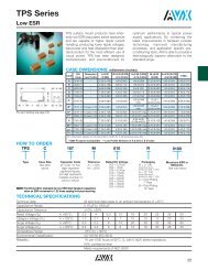
SMPS Capacitors<br />
Application Information on SupraCap TM<br />
SUPRACAP TM - LARGE CAPACITANCE VALUE MLCS<br />
High speed switch mode power supplies require extremely<br />
low equivalent series resistance (ESR) and equivalent-series<br />
inductance (ESL) capacitors for output filtering. These<br />
requirements are beyond the practical limits of electrolytic<br />
capacitors, both aluminum and tantalums, but are readily<br />
met by multilayer ceramic (MLCs) capacitors (Figure 1 and<br />
table on page 5).<br />
Theoretical SMPS’s output filter capacitor values are in the<br />
range of 6-10 µF/amp at 40KHz and drop to less than<br />
1 µF/amp at 1MHz. Most electrolytic applications use 10 to<br />
100 times the theoretical value in order to obtain lower ESR<br />
from paralleling many capacitors. This is not necessary with<br />
SupraCap MLC capacitors which inherently have ESRs in the<br />
range of milliohms. These extremely low values of ESR mean<br />
low ripple voltage and less self-heating of the capacitor.<br />
ESR (Ohms)<br />
100,000<br />
10,000<br />
1,000<br />
0.100<br />
0.010<br />
Aluminum<br />
Electrolytic<br />
ESR -vs- Frequency<br />
24 uFd Filter Capacitors<br />
Low "ESR"<br />
Tantalum<br />
Ceramic<br />
MLC<br />
0.001<br />
0.1 1.0 10.0 100.0 1000.0 10000.0<br />
Frequency (KHz)<br />
Output noise spikes are reduced by lowering the filter capacitance<br />
self-inductance. The ripple current is a triangle wave<br />
form with constant di/dt except when it changes polarity,<br />
then the di/dt is very high. The noise voltage generated by<br />
the filter capacitor is<br />
V Noise = L Capacitor di/dt<br />
<strong>AVX</strong>’s SupraCaps have inductance value less than 3nH.<br />
Figure 2 compares a 5.6 µF MLC to a 5.6 µF tantalum which<br />
was specially designed for low ESR and ESL. When subjected<br />
to a di/dt of 200 mA/ns the tantalum shows an ESR of<br />
165 mΩ and an ESL of 18nH versus the MLC’s 4 mΩ and<br />
0.3 nH. These performance differences allow considerable<br />
reduction in size and weight of the filter capacitor.<br />
Additionally, MLCs are compatible with surface mount technology<br />
reflow and assembly techniques which is the desirable<br />
assembly for conversion frequencies exceeding 1 MHz.<br />
Electrolytic capacitors (both aluminum and tantalum) are not<br />
compatible with normal vapor phase (VPS) or infrared (IR)<br />
reflow temperatures (205-215°C) due to electrolyte and<br />
structural problems. <strong>AVX</strong>’s SupraCaps are supplied with lead<br />
frames for either thru-hole or surface mount assembly. The<br />
lead frames act as stress relief for differences in coefficients<br />
of expansion between the large ceramic chip (10 ppm/°C)<br />
and the PC boards.<br />
DSW 16<br />
Ta<br />
50mV<br />
50nS<br />
TPOS-7<br />
Figure 1<br />
MLC<br />
CSW 1<br />
50mV<br />
V=2.0mV<br />
50nS<br />
VZR-0.2<br />
T=25.5nS<br />
Figure 2<br />
7
SMPS Capacitors<br />
Technical Information on SMPS Output Filter Capacitors<br />
ELECTRICAL SPECIFICATIONS<br />
Temperature Coefficient<br />
C0G: A Temperature Coefficient — 0 ±30 ppm/°C, -55° to +125°C<br />
X7R: C Temperature Coefficient — ±15%, -55° to +125°C<br />
Z5U: E Temperature Coefficient — +22, -56%, +10° to +85°C<br />
Capacitance Test (MIL-STD-202 Method 305)<br />
C0G: 25°C, 1.0±0.2 Vrms at 1KHz<br />
X7R: 25°C, 1.0±0.2 Vrms at 1KHz<br />
Z5U: 25°C, 0.5 Vrms max at 1KHz<br />
Dissipation Factor 25°C<br />
C0G: .15% Max @ 25°C, 1.0±0.2 Vrms at 1KHz<br />
X7R: 2.5% Max @ 25°C, 1.0±0.2 Vrms at 1KHz<br />
Z5U: 3.0% Max @ 25°C, 0.5 Vrms max at 1KHz<br />
Insulation Resistance 25°C (MIL-STD-202 Method 302)<br />
C0G and X7R: 100K MΩ or 1000 MΩ-µF whichever is less.<br />
Z5U: 10K MΩ or 1000 MΩ-µF whichever is less.<br />
Dielectric Withstanding Voltage 25°C (Flash Test)<br />
C0G and X7R: 250% rated voltage for 5 seconds with 50 mA max<br />
charging current. (500 Volt units @ 750 VDC.)<br />
Z5U: 200% rated voltage for 5 seconds with 50 mA max charging<br />
current.<br />
Life Test (1000 hrs)<br />
C0G and X7R: 200% rated voltage at +125°C. (500 Volt units @<br />
600 VDC.)<br />
Z5U: 150% rated voltage at +85°C<br />
Moisture Resistance (MIL-STD-202 Method 106)<br />
C0G, X7R, Z5U: Ten cycles with no voltage applied.<br />
Thermal Shock (MIL-STD-202 Method 107, Condition A)<br />
Immersion Cycling (MIL-STD-202 Method104, Condition B)<br />
Resistance To Solder Heat (MIL-STD-202, Method 210, Procedure 2,<br />
Condition C)<br />
Typical ESR (mΩ)<br />
24µF Performance<br />
Aluminum Tantalum MLC<br />
Electrolytic<br />
ESR @ 50KHz 2,100 140 1<br />
ESR @ 100KHz 2,000 125 1<br />
ESR @ 500KHz 1,600 105 2.5<br />
ESR @ 1MHz 1,500 105 5<br />
ESR @ 5MHz 1,200 140 10<br />
ESR @ 10MHz 1,700 190 14<br />
HOW TO ORDER:<br />
<strong>AVX</strong> styles: SM-1, SM-2, SM-3, SM-4, SM-5, SM-6<br />
SM0 1 7 C 106 M A N 650<br />
<strong>AVX</strong> Style Size Voltage Temperature Capacitance Capacitance Failure Termination Height<br />
Size See 50V = 5 Coefficient Code Tolerance Rate N = Straight Lead Max<br />
SM0 = Uncoated dimen- 100V = 1 C0G = A (2 significant C0G: J = ±5% A = Does J = Leads formed 120 = .120"<br />
SM5 = Epoxy sions 200V = 2 X7R = C digits + no. K = ±10% not apply in 240 = .240"<br />
coated chart 500V = 7 Z5U = E of zeros) M = ±20% L = Leads formed 360 = .360"<br />
10 pF = 100 X7R: K = ±10% out 480 = .480"<br />
100 pF = 101 M = ±20% 650 = .650"<br />
1,000 pF = 102 Z = +80, -20%<br />
22,000 pF = 223 Z5U: Z = +80, -20%<br />
220,000 pF = 224 P = GMV (+100, -0%)<br />
1 µF = 105<br />
10 µF = 106<br />
100 µF = 107<br />
Note: Capacitors with X7R and Z5U Dielectrics are not intended for AC line filtering applications. Contact Plant for recommendations.<br />
8
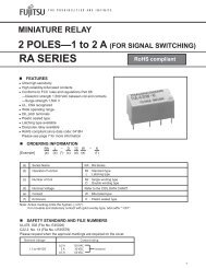
SMPS Capacitors<br />
Surface Mount and Thru Hole Series (SM0, SM5)<br />
D<br />
E<br />
CHIP SEPARATION<br />
.010 TYP.<br />
.010 RAD. (TYP.)<br />
B A<br />
0.055±.010<br />
.070±.010<br />
.075±.025 (TYP.)<br />
0.250 MIN.<br />
0.020 TYP.<br />
0.100 TYP.<br />
C<br />
0.010 TYP.<br />
"J" STYLE LEADS<br />
.010 RAD. (TYP.)<br />
0.100 MAX.<br />
0.025 MIN.<br />
"N" STYLE LEADS<br />
.070±.010<br />
.075±.025 (TYP.)<br />
"L" STYLE LEADS<br />
DIMENSION CHART<br />
No. of leads<br />
Style A (max.) B (max.) C ±.025 D ±.025 E (max.) per side<br />
SM-1 .650 .710 .450 2.050 .500 20<br />
SM-2 .650 .710 .800 1.510 .870 15<br />
SM-3 .650 .710 .450 1.050 .500 10<br />
SM-4 .650 .710 .400 .400 .440 4<br />
SM-5 .650 .710 .250 .250 .300 3<br />
SM-6 .650 .710 1.250 2.050 1.350 20<br />
Note: Dimensions A & B are max. dimensions for 5 chip stacks (.120 max. each chip).<br />
For SM5 add .005" to max. and NOM dimensions A, B, D, & E<br />
MAXIMUM CAPACITANCE AVAILABLE VERSUS STYLE<br />
<strong>AVX</strong> Style SM-1 SM-2 SM-3 SM-4 SM-5 SM-6<br />
Max Cap. (µF)*<br />
C0G (NP0)<br />
X7R<br />
50V<br />
5.00<br />
130.0<br />
100V<br />
3.50<br />
60.0<br />
200V<br />
1.90<br />
27.0<br />
500V<br />
0.90<br />
13.0<br />
50V<br />
6.00<br />
200.0<br />
100V<br />
5.00<br />
90.0<br />
200V<br />
2.80<br />
42.0<br />
500V<br />
1.30<br />
20.0<br />
50V<br />
2.30<br />
90.0<br />
100V<br />
1.90<br />
30.0<br />
200V<br />
1.00<br />
14.0<br />
500V<br />
0.45<br />
6.50<br />
50V<br />
0.80<br />
36.0<br />
100V<br />
0.65<br />
9.00<br />
200V<br />
0.35<br />
5.50<br />
500V<br />
0.12<br />
2.00<br />
50V<br />
0.25<br />
12.00<br />
100V<br />
0.20<br />
3.40<br />
200V<br />
0.10<br />
1.60<br />
500V<br />
0.05<br />
0.80<br />
50V<br />
16.0<br />
400<br />
100V<br />
12.0<br />
200<br />
200V<br />
6.50<br />
120<br />
500V<br />
2.50<br />
45.0<br />
Z5U<br />
420.0 160.0 60.0 – – 590.0 230.0 170.0 – – 200.0 75.0 30.0 – – 60.0 23.0 15.0 – – 23.0 9.00 3.60 – – 1300 720 460 – –<br />
No. of Leads/side** 20 15 10 4 3 20<br />
Standard Max. Stack* 5 5 5 5 5 5<br />
* Values given are for 5 chips stacked. For maximum per chip divide by 5. Maximum thickness per individual chip equals 0.120".<br />
** Based on 0.100" centers.<br />
Note: Contact factory for other voltage ratings.<br />
EXAMPLE OF HOW TO ORDER<br />
SM04 200 volt X7R<br />
Maximum capacitance for 5 section unit is 5.5 µF (as seen in above table).<br />
This would be 1.1 µF per chip.<br />
Maximum capacitance for 1 chip (single) is 1.1 µF SM042C115KAN120<br />
Maximum capacitance for 2 chips stacked is 2.2 µF SM042C225KAN240<br />
Maximum capacitance for 3 chips stacked is 3.3 µF SM042C335KAN360<br />
Maximum capacitance for 4 chips stacked is 4.4 µF SM042C445KAN480<br />
Maximum capacitance for 5 chips stacked is 5.5 µF SM042C555KAN650<br />
9
SMPS Capacitors<br />
Plastic Case (SM9)<br />
D .010<br />
E +.000<br />
-.010<br />
+ -<br />
+ -<br />
Maximum Height<br />
(see table)<br />
0.015<br />
.005<br />
+ -<br />
.002<br />
0.250 (MIN.)<br />
0.100 CENTERS (TYP.)<br />
0.020<br />
+ - .002<br />
+ -<br />
0.010<br />
C .025<br />
HOW TO ORDER:<br />
<strong>AVX</strong> styles: SM91, SM92, SM93, SM94, SM95, SM96<br />
SM9 1 7 C 106 M A N 660<br />
<strong>AVX</strong> Style Size Voltage Temperature Capacitance Capacitance Failure Termination Height<br />
Size See 50V = 5 Coefficient Code Tolerance Rate N = Straight Lead See Table<br />
SM9 = Plastic Case dimen- 100V = 1 C0G = A (2 significant C0G: J = ±5% A = Does J = Leads formed on next<br />
sions 200V = 2 X7R = C digits + no. K = ±10% not apply in page for<br />
chart 500V = 7 Z5U = E of zeros) M = ±20% L = Leads formed max cap.<br />
10 pF = 100 X7R: K = ±10% out per<br />
100 pF = 101 M = ±20% height<br />
1,000 pF = 102 Z = +80, -20%<br />
22,000 pF = 223 Z5U: Z = +80, -20%<br />
220,000 pF = 224 P = GMV (+100, -0%)<br />
1 µF = 105<br />
10 µF = 106<br />
100 µF = 107<br />
Note: Capacitors with X7R and Z5U Dielectrics are not intended for AC line filtering applications. Contact Plant for recommendations.<br />
10<br />
DIMENSION CHART<br />
Case Code C D E<br />
No. of leads<br />
per side*<br />
SM91 0.450 2.155 0.580 20<br />
SM92 0.800 1.615 0.950 15<br />
SM93 0.450 1.155 0.580 10<br />
SM94 0.400 0.485 0.485 4<br />
SM95 0.250 0.355 0.355 3<br />
SM96 1.250 2.155 1.430 20<br />
*Leads styles N, J or L available
SMPS Capacitors<br />
Max Cap (µF) Available Versus Style with Height of .270"<br />
<strong>AVX</strong><br />
STYLE<br />
C0G<br />
X7R<br />
Z5U<br />
SM91 _ _ _ _ _ A N270 SM92 _ _ _ _ _ _ A N270 SM93 _ _ _ _ A N270 SM94 _ _ _ _ A N270 SM95 _ _ _ _ _ A N270 SM96 _ _ _ _ _ A N270<br />
50V 100V 200V 500V 50V 100V 200V 500V 50V 100V 200V 500V 50V 100V 200V 500V 50V 100V 200V 500V 50V 100V 200V 500V<br />
1.0 .70 .38 .18 1.2 1.0 .56 .26 .46 .38 .20 .09 .16 .13 .07 .02 .05 .04 .02 .01 3.2 2.4 1.3 .50<br />
27 12 5.4 2.6 40 18 8.4 4.0 18 6.0 2.8 1.3 7.2 1.8 1.1 .40 2.4 .68 .32 .16 80 40 24 9.0<br />
84 32 12 – – 110 46 34 – – 40 15 6.0 – – 12 4.6 3.0 – – 4.6 1.8 .72 – – 260 140 92 – –<br />
Max Cap (µF) Available Versus Style with Height of .390"<br />
<strong>AVX</strong><br />
STYLE<br />
C0G<br />
X7R<br />
Z5U<br />
SM91 _ _ _ _ _ A N390 SM92 _ _ _ _ _ _ A N390 SM93 _ _ _ _ A N390 SM94 _ _ _ _ A N390 SM95 _ _ _ _ _ A N390 SM96 _ _ _ _ _ A N390<br />
50V 100V 200V 500V 50V 100V 200V 500V 50V 100V 200V 500V 50V 100V 200V 500V 50V 100V 200V 500V 50V 100V 200V 500V<br />
2.0 1.4 .76 .36 2.4 2.0 1.1 .52 .92 .76 .40 .18 .32 .26 .14 .04 .10 .08 .04 .02 6.4 4.8 2.6 1.0<br />
54 24 10 5.2 80 36 16 8.0 36 12 5.6 2.6 14 3.6 2.2 .80 4.8 1.3 .64 .32 160 80 48 18<br />
160 64 24 – – 230 92 68 – – 80 30 12 – – 24 9.2 6.0 – – 9.2 3.6 1.4 – – 520 280 180 – –<br />
Max Cap (µF) Available Versus Style with Height of .530"<br />
<strong>AVX</strong><br />
STYLE<br />
C0G<br />
X7R<br />
Z5U<br />
SM91 _ _ _ _ _ A N530 SM92 _ _ _ _ _ _ A N530 SM93 _ _ _ _ A N530 SM94 _ _ _ _ A N530 SM95 _ _ _ _ _ A N530 SM96 _ _ _ _ _ A N530<br />
50V 100V 200V 500V 50V 100V 200V 500V 50V 100V 200V 500V 50V 100V 200V 500V 50V 100V 200V 500V 50V 100V 200V 500V<br />
3.0 2.1 1.1 .54 3.6 3.0 1.6 .78 1.3 1.1 .60 .27 .48 .39 .21 .07 .15 .12 .06 .03 9.6 7.2 3.9 1.5<br />
81 36 16 7.8 120 54 25 12 54 18 8.4 3.9 21 5.4 3.3 1.2 7.2 2.0 .96 .48 240 120 72 27<br />
250 96 36 – – 350 130 100 – – 120 45 18 – – 36 13 9.0 – – 13 5.4 2.1 – – 780 430 270 – –<br />
Max Cap (µF) Available Versus Style with Height of .660"<br />
<strong>AVX</strong><br />
STYLE<br />
C0G<br />
X7R<br />
Z5U<br />
SM91 _ _ _ _ _ A N660 SM92 _ _ _ _ _ _ A N660 SM93 _ _ _ _ A N660 SM94 _ _ _ _ A N660 SM95 _ _ _ _ _ A N660 SM96 _ _ _ _ _ A N660<br />
50V 100V 200V 500V 50V 100V 200V 500V 50V 100V 200V 500V 50V 100V 200V 500V 50V 100V 200V 500V 50V 100V 200V 500V<br />
4.0 2.8 1.5 .72 4.8 4.0 2.2 1.0 1.8 1.5 .80 .36 .64 .52 .28 .09 .20 .16 .08 .04 12 9.6 5.2 2.0<br />
100 48 21 10 160 72 33 16 72 24 11 5.2 28 7.2 4.4 1.6 9.6 2.7 1.2 .64 320 160 96 36<br />
330 120 48 – – 470 180 130 – – 160 60 24 – – 48 18 12 – – 18 7.2 2.8 – – 1000 570 360 – –<br />
Max Cap (µF) Available Versus Style with Height of .800"<br />
<strong>AVX</strong><br />
STYLE<br />
C0G<br />
X7R<br />
Z5U<br />
SM91 _ _ _ _ _ A N800 SM92 _ _ _ _ _ _ A N800 SM93 _ _ _ _ A N800 SM94 _ _ _ _ A N800 SM95 _ _ _ _ _ A N800 SM96 _ _ _ _ _ A N800<br />
50V 100V 200V 500V 50V 100V 200V 500V 50V 100V 200V 500V 50V 100V 200V 500V 50V 100V 200V 500V 50V 100V 200V 500V<br />
5.0 3.5 1.9 .90 6.0 5.0 2.8 1.3 2.3 1.9 1.0 .45 .80 .65 .35 .12 .25 .20 .10 .05 16 12 6.5 2.5<br />
130 60 27 13 200 90 42 20 90 30 14 6.5 36 9.0 5.5 2.0 12 3.4 1.6 .80 400 200 120 45<br />
420 160 60 – – 590 230 170 – – 200 75 30 – – 60 23 15 – – 23 9.0 3.6 – – 1300 720 460 – –<br />
11
SMPS Capacitors<br />
SK Series/SMPS Capacitors<br />
Product Offering – C0G, X7R<br />
and Z5U<br />
<strong>Olean</strong> <strong>Advanced</strong> <strong>Products</strong>’ SK series are conformally<br />
coated MLC capacitors for input or output filtering<br />
in switch mode power supplies. They are specially<br />
processed to handle high currents and are low<br />
enough in cost for commercial SMPS application.<br />
HOW TO ORDER:<br />
SK 01 3 E 125 Z A A *<br />
Style<br />
Size<br />
See chart<br />
below<br />
Voltage<br />
25V = 3<br />
50V = 5<br />
100V = 1<br />
200V = 2<br />
500V = 7<br />
Temperature<br />
Coefficient<br />
Z5U = E<br />
X7R = C<br />
C0G = A<br />
Capacitance<br />
Code<br />
(2 significant<br />
digits + no.<br />
of zeros)<br />
22 nF = 223<br />
220 nF = 224<br />
1 µF = 105<br />
100 µF = 107<br />
Capacitance<br />
Tolerance<br />
C0G: J = ±5%<br />
K = ±10%<br />
M = ±20%<br />
X7R: K = ±10%<br />
M = ±20%<br />
Z = +80, -20%<br />
Z5U: Z = +80, -20%<br />
P = GMV (+100, -0%)<br />
Failure<br />
Rate<br />
A = Does<br />
not apply<br />
Leads<br />
A = Does<br />
not apply<br />
Packaging<br />
(See Note 1)<br />
Note 1: No suffix signifies bulk packaging,<br />
which is <strong>AVX</strong>’s standard packaging.<br />
SK01, SK * 3, SK * 4 & SK * 5 are available<br />
taped and reel per EIA-468. Use<br />
suffix “TR1” if tape & reel is required.<br />
Note: Capacitors with X7R and Z5U Dielectrics are not intended for AC line filtering applications. Contact Plant for recommendations.<br />
Maximum Capacitance Values (C0G), µFd<br />
Style<br />
25 50 100 200 500<br />
WVDC WVDC WVDC WVDC WVDC<br />
SK01 .015 .012 .010 .0056 .0018<br />
SK03/SK53 .056 .047 .039 .022 .0068<br />
SK04/SK54 .12 .10 .082 .047 .015<br />
SK05/SK55 .18 .15 .12 .068 .022<br />
SK06 .56 .47 .39 .22 .068<br />
SK07 .68 .56 .47 .27 .082<br />
SK08 1.20 1.10 .82 .47 .15<br />
Maximum Capacitance Values (X7R), µFd<br />
Style<br />
25 50 100 200 500<br />
WVDC WVDC WVDC WVDC WVDC<br />
SK01 0.39 0.27 0.15 0.082 0.033<br />
SK03/SK53 2.2 1.0 0.56 0.39 0.15<br />
SK04/SK54 4.7 2.2 1.2 0.68 0.27<br />
SK05/SK55 6.8 3.3 1.8 1.2 0.47<br />
SK06 15 10 5.6 3.9 1.2<br />
SK07 18 14 8.2 4.7 1.8<br />
SK08 33 22 15 8.2 3.3<br />
Maximum Capacitance Values (Z5U), µFd<br />
Style 25 WVDC 50 WVDC 100 WVDC 200 WVDC<br />
SK01 1.2 0.82 0.47 0.33<br />
SK03/SK53 5.6 3.30 2.20 1.50<br />
SK04/SK54 10.0 8.20 4.70 3.30<br />
SK05/SK55 18.0 10.00 6.80 4.70<br />
SK06 47.0 39.00 22.00 15.00<br />
SK07 68.0 47.00 27.00 18.00<br />
SK08 120.0 100.00 47.00 33.00<br />
12
SK Series/SMPS Capacitors<br />
Product Offering – C0G, X7R and Z5U<br />
L<br />
L<br />
L<br />
T<br />
H<br />
H<br />
H + 0.145"<br />
H<br />
LL<br />
M<br />
LD<br />
LL<br />
LD<br />
M<br />
LD<br />
M<br />
LL<br />
LS<br />
LS<br />
LS<br />
SK01 SK03 – SK08 SK53 – SK55<br />
DIMENSION CHART<br />
Style L (max.) H (max.) T (max.) LS (nom.) LD (nom.)<br />
SK01 0.200 0.200 0.200 0.200 0.020<br />
SK03/SK53 0.300 0.300 0.200 0.200 0.020<br />
SK04/SK54 0.400 0.400 0.200 0.200 0.020<br />
SK05/SK55 0.500 0.500 0.200 0.400 0.025<br />
SK06 0.870 0.600 0.200 0.790 0.032<br />
SK07 1.100 0.600 0.200 0.980 0.032<br />
SK08 1.100 0.600 0.350 0.980 0.032<br />
L = Length T = Thickness LS = Lead Spacing (Nominal ±0.031)<br />
H = Height M = Meniscus (0.060 max.) LL = Lead Length (2" max./1" min.)<br />
LD = Lead Diameter (Nominal ±0.002)<br />
TAPE & REEL QUANTITY<br />
Part<br />
Pieces<br />
SK01 2000<br />
SK03/SK53 1000<br />
SK04/SK54 1000<br />
SK05/SK55 750<br />
13
SMPS Capacitors<br />
SM Military Series DSCC Dwg. #87106 & #88011<br />
D<br />
E<br />
CHIP SEPARATION<br />
.010 TYP.<br />
B<br />
A<br />
0.055±.010<br />
0.250 MIN.<br />
0.020 TYP.<br />
0.100 TYP.<br />
0.100 MAX.<br />
0.025 MIN.<br />
(Note 5)<br />
C<br />
0.010 TYP.<br />
"N" STYLE LEADS<br />
.010 RAD. (TYP.)<br />
.070±.010<br />
.075±.025 (TYP.)<br />
SCHEMATIC<br />
"J" STYLE LEADS<br />
DIMENSION CHART<br />
Case A (max.) B (max.) No. of leads<br />
Code (See Note 3) (See Note 3) C ±.025 D ±.025 E (max.) per side<br />
1 .650 .715 .450 2.050 .500 20<br />
2 .650 .715 .800 1.510 .870 15<br />
3 .650 .715 .450 1.050 .500 10<br />
4 .650 .715 .400 .400 .440 4<br />
5 .650 .715 .250 .250 .300 3<br />
6 .650 .715 1.250 2.050 1.350 20<br />
NOTES:<br />
1. Dimensions are in inches.<br />
2. Unless otherwise specified, tolerances ±.010.<br />
3. “A” dimensions are maximum (see tables on pages 17 thru 20 for specific part number dimensions).<br />
4. “N” straight leads; “J” leads formed in.<br />
5. For case code 5, dimensions shall be .100 maximum, .012 minimum.<br />
Figure 1. Dimensions and configurations.<br />
14
SMPS Capacitors<br />
SM Military Series DSCC Dwg. #87106 & 88011<br />
Ordering Information<br />
Part Number: The complete part number shall be as follows:<br />
X7R: 87016 XXX<br />
_________________<br />
______________<br />
Drawing number<br />
Dash number<br />
(see list)<br />
Ordering Data. The contract or purchase order should<br />
specify the following:<br />
a. Complete part number.<br />
b. Requirements for delivery of one copy of the quality conformance<br />
inspection data with each shipment of parts by<br />
the manufacturer.<br />
c. Whether the manufacturer performs the group B tests, or<br />
provides certification of compliance with group B requirements.<br />
d. Requirements for notification of change of products to<br />
acquiring activity, if applicable.<br />
e. Requirements for packaging and packing.<br />
Source of Supply.<br />
Vendor CAGE<br />
number<br />
Vendor name<br />
and address<br />
96095 <strong>Olean</strong> <strong>Advanced</strong> <strong>Products</strong><br />
A Division of <strong>AVX</strong> Corporation<br />
1695 Seneca Avenue<br />
<strong>Olean</strong>, NY 14760<br />
Performance Characteristics<br />
Operating Temperature Range. The operating temperature<br />
range shall be -55°C to +125°C.<br />
Electrical Characteristics.<br />
Rated Voltage. See tables on pages 17, 18, 19 & 20.<br />
Dissipation Factor (+25°C). X7R: Dissipation factor shall be 2.5<br />
percent maximum (measured under the same conditions as<br />
capacitance.) C0G: Dissipation factor shall be .15 percent maximum.<br />
Capacitance. Measured in accordance with method 305 of<br />
MIL-STD-202 (1KHz at 1.0Vrms, open circuit voltage, at +25°C).<br />
Temperature Coefficient.<br />
DSCC Dwg. Bias = 0 volt Bias = rated voltage<br />
88011 All Voltages 0±30 ppm/°C 0±30 ppm/°C<br />
87106 50 WV dc ±15% ±15, -25%<br />
and 100 WV dc<br />
87106 200 WV dc ±15% ±15, -40%<br />
87106 500 WV dc ±15% ±15, -45%<br />
Insulation Resistance.<br />
At +25°C, rated voltage: 100K MΩ or 1,000 MΩ-µF,<br />
whichever is less.<br />
At +125°C, rated voltage: 10K MΩ<br />
whichever is less.<br />
or 100 MΩ-µF,<br />
Dielectric Withstanding Voltage. Dielectric withstanding voltage<br />
shall be 2.5 times rated voltage except 500V rated parts at<br />
1.5 times rated voltage.<br />
Capacitance Tolerance.<br />
M = ±20 percent.<br />
J = ±5 percent, K = ±10 percent,<br />
Solderability of Terminals. In accordance with MIL-C-39014<br />
or MIL-C-20.<br />
Resistance to Soldering Heat. In accordance with MIL-STD-<br />
202, method 210, procedure 2, condition B.<br />
Shock. In accordance with MIL-C-39014 or MIL-C-20.<br />
Immersion Cycling. In accordance with MIL-C-39014 or MIL-<br />
C-20.<br />
Moisture Resistance. In accordance with MIL-C-39014 or<br />
MIL-C-20.<br />
Life. Life shall be 200 percent of rated voltage except 500V<br />
rated parts at 120 percent of rated voltage applied at +125°C for<br />
1,000 hours.<br />
Thermal Shock. MIL-STD-202, method 107, test condition A,<br />
except high temperature is +125°C.<br />
Voltage Conditioning. In accordance with MIL-C-39014 or<br />
MIL-C-20, except 500V rated parts at 120 percent of rated voltage<br />
at +125°C.<br />
Terminal Strength. MIL-STD-202, method 211, condition B,<br />
except that each lead shall be bent away from the body 90<br />
degrees from the original position and back, two bends.<br />
Marking. Marking shall be in accordance with MIL-STD-1285,<br />
except the part number shall be as specified in 1.2 with the manufacturer’s<br />
name or code and date code minimum, except case<br />
sizes 4 and 5 shall be marked with coded cap and tolerance minimum.<br />
Full marking shall be included on the package.<br />
15
SMPS Capacitors<br />
DSCC #87106<br />
Inspection<br />
Requirement<br />
paragraph<br />
of<br />
MIL-C-39014<br />
Group A<br />
Test Method<br />
paragraph<br />
of<br />
MIL-C-39014<br />
Subgroup 1<br />
Thermal Shock and<br />
Voltage conditioning 1 / . . . . 3.6 4.7.2 100% inspection<br />
AQL (percent defective)<br />
and LQ (limiting quality)<br />
(percent defective)<br />
Major<br />
Minor<br />
Subgroup 2<br />
Visual and mechanical<br />
examination<br />
Material . . . 3.4 and 4.7.1<br />
3.4.1<br />
Physical<br />
dimensions . . . 3.1 1.0 (AQL) 4.0 (AQL)<br />
Design and<br />
construction<br />
(Other than physical 3.5 and 7.6 (LQ) 18 (LQ)<br />
dimensions) 3.5.1<br />
Marking<br />
Workmanship . . . . 3.28<br />
1 / 500 WVDC capacitors shall be tested at 600 VDC.<br />
Group B<br />
Inspection<br />
Requirement Test Method Number of Number of<br />
paragraph paragraph Sample Units defectives<br />
of of to be permitted<br />
MIL-C-39014 MIL-C-39014 inspected 1 /<br />
Subgroup 1<br />
Voltage-temperature<br />
limits . . . . 3.14 4.7.10.2<br />
Vibration, high<br />
frequency . . . . 3.15 4.7.11 18 1<br />
Immersion . . . . 3.16 4.7.12<br />
Subgroup 2<br />
Shock, specified<br />
pulse . . . . 3.18 4.7.14<br />
Terminal<br />
strength . . . . 18 1<br />
Moisture Resistance 3.20 4.7.16<br />
Subgroup 3<br />
Barometric pressure 3.10 4.7.6 6 1<br />
Low Temp. Storage 3.25 4.7.21<br />
Subgroup 4<br />
Resistance to<br />
soldering heat . . . . 3.22 4.7.18<br />
Solderability . . . . 3.13 4.7.9 4 0<br />
Resistance to<br />
solvents . . . .<br />
(Ink and OLM only) 3.23 4.7.19<br />
Subgroup 5<br />
Life (1,000 hours<br />
accelerated condition)<br />
See<br />
2 / . . . . 3.24 4.7.20.2.2 5 minimum 4.6.2.1.1.2<br />
per case code<br />
of MIL-C-39014<br />
1 / A sample unit having one or more defects shall be charged as a single defect.<br />
2 / 500 WVDC capacitors shall be tested at 600 VDC.<br />
16
SMPS Capacitors<br />
SM Military Series DSCC Dwg. #87106<br />
Electrical characteristics<br />
DSCC Cap.<br />
Dwg. Value Cap. Case Lead Max. A<br />
87106- (µF) Tol. Code Style Dimension<br />
50V<br />
001 1.0 K 5 N .120<br />
002 1.0 M 5 N .120<br />
241 1.0 K 5 J .120<br />
242 1.0 M 5 J .120<br />
003 1.2 K 5 N .120<br />
004 1.2 M 5 N .120<br />
243 1.2 K 5 J .120<br />
244 1.2 M 5 J .120<br />
005 1.5 K 5 N .240<br />
006 1.5 M 5 N .240<br />
245 1.5 K 5 J .240<br />
246 1.5 M 5 J .240<br />
007 1.8 K 5 N .240<br />
008 1.8 M 5 N .240<br />
247 1.8 K 5 J .240<br />
248 1.8 M 5 J .240<br />
009 2.2 K 5 N .240<br />
010 2.2 M 5 N .240<br />
249 2.2 K 5 J .240<br />
250 2.2 M 5 J .240<br />
011 2.7 K 5 N .360<br />
012 2.7 M 5 N .360<br />
251 2.7 K 5 J .360<br />
252 2.7 M 5 J .360<br />
013 3.3 K 5 N .360<br />
014 3.3 M 5 N .360<br />
253 3.3 K 5 J .360<br />
254 3.3 M 5 J .360<br />
015 3.9 K 5 N .480<br />
016 3.9 M 5 N .480<br />
255 3.9 K 5 J .480<br />
256 3.9 M 5 J .480<br />
017 4.7 K 5 N .480<br />
018 4.7 M 5 N .480<br />
257 4.7 K 5 J .480<br />
258 4.7 M 5 J .480<br />
019 5.6 K 5 N .650<br />
020 5.6 M 5 N .650<br />
259 5.6 K 5 J .650<br />
260 5.6 M 5 J .650<br />
223 6.8 K 4 N .360<br />
224 6.8 M 4 N .360<br />
261 6.8 K 4 J .360<br />
262 6.8 M 4 J .360<br />
021 8.2 K 4 N .360<br />
022 8.2 M 4 N .360<br />
263 8.2 K 4 J .360<br />
264 8.2 M 4 J .360<br />
023 10 K 4 N .480<br />
024 10 M 4 N .480<br />
265 10 K 4 J .480<br />
266 10 M 4 J .480<br />
025 12 K 4 N .480<br />
026 12 M 4 N .480<br />
267 12 K 4 J .480<br />
268 12 M 4 J .480<br />
027 15 K 4 N .650<br />
028 15 M 4 N .650<br />
269 15 K 4 J .650<br />
270 15 M 4 J .650<br />
029 18 K 3 N .240<br />
030 18 M 3 N .240<br />
271 18 K 3 J .240<br />
DSCC Cap.<br />
Dwg. Value Cap. Case Lead Max. A<br />
87106- (µF) Tol. Code Style Dimension<br />
50V<br />
272 18 M 3 J .240<br />
272 18 M 3 J .240<br />
031 22 K 3 N .360<br />
032 22 M 3 N .360<br />
273 22 K 3 J .360<br />
274 22 M 3 J .360<br />
033 27 K 3 N .360<br />
034 27 M 3 N .360<br />
275 27 K 3 J .360<br />
276 27 M 3 J .360<br />
035 33 K 3 N .360<br />
036 33 M 3 N .360<br />
277 33 K 3 J .360<br />
278 33 M 3 J .360<br />
037 39 K 3 N .480<br />
038 39 M 3 N .480<br />
279 39 K 3 J .480<br />
280 39 M 3 J .480<br />
039 47 K 3 N .650<br />
040 47 M 3 N .650<br />
281 47 K 3 J .650<br />
282 47 M 3 J .650<br />
225 56 K 1 N .360<br />
226 56 M 1 N .360<br />
283 56 K 1 J .360<br />
284 56 M 1 J .360<br />
041 68 K 1 N .480<br />
042 68 M 1 N .480<br />
285 68 K 1 J .480<br />
286 68 M 1 J .480<br />
043 82 K 1 N .480<br />
044 82 M 1 N .480<br />
287 82 K 1 J .480<br />
288 82 M 1 J .480<br />
045 100 K 1 N .650<br />
046 100 M 1 N .650<br />
289 100 K 1 J .650<br />
290 100 M 1 J .650<br />
227 120 K 2 N .480<br />
228 120 M 2 N .480<br />
291 120 K 2 J .480<br />
292 120 M 2 J .480<br />
047 150 K 2 N .650<br />
048 150 M 2 N .650<br />
293 150 K 2 J .650<br />
294 150 M 2 J .650<br />
049 180 K 6 N .480<br />
050 180 M 6 N .480<br />
295 180 K 6 J .480<br />
296 180 M 6 J .480<br />
051 220 K 6 N .480<br />
052 220 M 6 N .480<br />
297 220 K 6 J .480<br />
298 220 M 6 J .480<br />
053 270 K 6 N .650<br />
054 270 M 6 N .650<br />
299 270 K 6 J .650<br />
300 270 M 6 J .650<br />
DSCC Cap.<br />
Dwg. Value Cap. Case Lead Max. A<br />
87106- (µF) Tol. Code Style Dimension<br />
100V<br />
055 .68 K 5 N .120<br />
056 .68 M 5 N .120<br />
301 .68 K 5 J .120<br />
302 .68 M 5 J .120<br />
057 .82 K 5 N .240<br />
058 .82 M 5 N .240<br />
303 .82 K 5 J .240<br />
304 .82 M 5 J .240<br />
059 1.0 K 5 N .240<br />
060 1.0 M 5 N .240<br />
305 1.0 K 5 J .240<br />
306 1.0 M 5 J .240<br />
061 1.2 K 5 N .240<br />
062 1.2 M 5 N .240<br />
307 1.2 K 5 J .240<br />
308 1.2 M 5 J .240<br />
063 1.5 K 5 N .360<br />
064 1.5 M 5 N .360<br />
309 1.5 K 5 J .360<br />
310 1.5 M 5 J .360<br />
065 1.8 K 5 N .360<br />
066 1.8 M 5 N .360<br />
311 1.8 K 5 J .360<br />
312 1.8 M 5 J .360<br />
067 2.2 K 5 N .480<br />
068 2.2 M 5 N .480<br />
313 2.2 K 5 J .480<br />
314 2.2 M 5 J .480<br />
069 2.7 K 5 N .480<br />
070 2.7 M 5 N .480<br />
315 2.7 K 5 J .480<br />
316 2.7 M 5 J .480<br />
071 3.3 K 5 N .650<br />
072 3.3 M 5 N .650<br />
317 3.3 K 5 J .650<br />
318 3.3 M 5 J .650<br />
073 3.9 K 4 N .360<br />
074 3.9 M 4 N .360<br />
319 3.9 K 4 J .360<br />
320 3.9 M 4 J .360<br />
075 4.7 K 4 N .360<br />
076 4.7 M 4 N .360<br />
321 4.7 K 4 J .360<br />
322 4.7 M 4 J .360<br />
077 5.6 K 4 N .480<br />
078 5.6 M 4 N .480<br />
323 5.6 K 4 J .480<br />
324 5.6 M 4 J .480<br />
079 6.8 K 4 N .480<br />
080 6.8 M 4 N .480<br />
325 6.8 K 4 J .480<br />
326 6.8 M 4 J .480<br />
081 8.2 K 4 N .650<br />
082 8.2 M 4 N .650<br />
327 8.2 K 4 J .650<br />
328 8.2 M 4 J .650<br />
229 10 K 3 N .240<br />
230 10 M 3 N .240<br />
329 10 K 3 J .240<br />
330 10 M 3 J .240<br />
083 12 K 3 N .240<br />
084 12 M 3 N .240<br />
331 12 K 3 J .240<br />
332 12 M 3 J .240<br />
17
SMPS Capacitors<br />
SM Military Series DSCC Dwg. #87106<br />
Electrical characteristics<br />
DSCC Cap.<br />
Dwg. Value Cap. Case Lead Max. A<br />
87106- (µF) Tol. Code Style Dimension<br />
100V<br />
085 15 K 3 N .360<br />
086 15 M 3 N .360<br />
333 15 K 3 J .360<br />
334 15 M 3 J .360<br />
087 18 K 3 N .360<br />
088 18 M 3 N .360<br />
335 18 K 3 J .360<br />
336 18 M 3 J .360<br />
089 22 K 3 N .480<br />
090 22 M 3 N .480<br />
337 22 M 3 K .480<br />
338 22 M 3 J .480<br />
091 27 K 3 N .650<br />
092 27 M 3 N .650<br />
339 27 K 3 J .650<br />
340 27 M 3 J .650<br />
093 33 K 1 N .360<br />
094 33 M 1 N .360<br />
341 33 K 1 J .360<br />
342 33 M 1 J .360<br />
095 39 K 1 N .480<br />
096 39 M 1 N .480<br />
343 39 K 1 J .480<br />
344 39 M 1 J .480<br />
097 47 K 1 N .480<br />
098 47 M 1 N .480<br />
345 47 K 1 J .480<br />
346 47 M 1 J .480<br />
099 56 K 1 N .650<br />
100 56 M 1 N .650<br />
347 56 K 1 J .650<br />
348 56 M 1 J .650<br />
101 68 K 2 N .480<br />
102 68 M 2 N .480<br />
349 68 K 2 J .480<br />
350 68 M 2 J .480<br />
103 82 K 2 N .650<br />
104 82 M 2 N .650<br />
351 82 K 2 J .650<br />
352 82 M 2 J .650<br />
105 100 K 6 N .360<br />
106 100 M 6 N .360<br />
353 100 K 6 J .360<br />
354 100 M 6 J .360<br />
107 120 K 6 N .360<br />
108 120 M 6 N .360<br />
355 120 K 6 J .360<br />
356 120 M 6 J .360<br />
109 150 K 6 N .480<br />
110 150 M 6 N .480<br />
357 150 K 6 J .480<br />
358 150 M 6 J .480<br />
111 180 K 6 N .650<br />
112 180 M 6 N .650<br />
359 180 K 6 J .650<br />
360 180 M 6 J .650<br />
DSCC Cap.<br />
Dwg. Value Cap. Case Lead Max. A<br />
87106- (µF) Tol. Code Style Dimension<br />
200V<br />
113 .47 K 5 N .240<br />
114 .47 M 5 N .240<br />
361 .47 K 5 J .240<br />
362 .47 M 5 J .240<br />
115 .56 K 5 N .240<br />
116 .56 M 5 N .240<br />
363 .56 K 5 J .240<br />
364 .56 M 5 J .240<br />
117 .68 K 5 N .360<br />
118 .68 M 5 N .360<br />
365 .68 K 5 J .360<br />
366 .68 M 5 J .360<br />
119 .82 K 5 N .360<br />
120 .82 M 5 N .360<br />
367 .82 M 5 J .360<br />
368 .82 M 5 J .360<br />
121 1.0 K 5 N .480<br />
122 1.0 M 5 N .480<br />
369 1.0 K 5 J .480<br />
370 1.0 M 5 J .480<br />
123 1.2 K 5 N .480<br />
124 1.2 M 5 N .480<br />
371 1.2 K 5 J .480<br />
372 1.2 M 5 J .480<br />
125 1.5 K 5 N .650<br />
126 1.5 M 5 N .650<br />
373 1.5 K 5 J .650<br />
374 1.5 M 5 J .650<br />
127 1.8 K 4 N .360<br />
128 1.8 M 4 N .360<br />
375 1.8 K 4 J .360<br />
376 1.8 M 4 J .360<br />
129 2.2 K 4 N .360<br />
130 2.2 M 4 N .360<br />
377 2.2 K 4 J .360<br />
378 2.2 M 4 J .360<br />
131 2.7 K 4 N .480<br />
132 2.7 M 4 N .480<br />
379 2.7 K 4 J .480<br />
380 2.7 M 4 J .480<br />
133 3.3 K 4 N .480<br />
134 3.3 M 4 N .480<br />
381 3.3 K 4 J .480<br />
382 3.3 M 4 J .480<br />
135 3.9 K 4 N .650<br />
136 3.9 M 4 N .650<br />
383 3.9 K 4 J .650<br />
384 3.9 M 4 J .650<br />
137 4.7 K 3 N .240<br />
138 4.7 M 3 N .240<br />
385 4.7 K 3 J .240<br />
386 4.7 M 3 J .240<br />
139 5.6 K 3 N .240<br />
140 5.6 M 3 N .240<br />
387 5.6 K 3 J .240<br />
388 5.6 M 3 J .240<br />
141 6.8 K 3 N .360<br />
142 6.8 M 3 N .360<br />
389 6.8 K 3 J .360<br />
390 6.8 M 3 J .360<br />
143 8.2 K 3 N .360<br />
144 8.2 M 3 N .360<br />
391 8.2 K 3 J .360<br />
392 8.2 M 3 J .360<br />
DSCC Cap.<br />
Dwg. Value Cap. Case Lead Max. A<br />
87106- (µF) Tol. Code Style Dimension<br />
200V<br />
145 10 K 3 N .480<br />
146 10 M 3 N .480<br />
393 10 K 3 J .480<br />
394 10 M 3 J .480<br />
147 12 K 3 N .650<br />
148 12 M 3 N .650<br />
395 12 K 3 J .650<br />
396 12 M 3 J .650<br />
149 15 K 1 N .360<br />
150 15 M 1 N .360<br />
397 15 K 1 J .360<br />
398 15 M 1 J .360<br />
151 18 K 1 N .480<br />
152 18 M 1 N .480<br />
399 18 K 1 J .480<br />
400 18 M 1 J .480<br />
153 22 K 1 N .650<br />
154 22 M 1 N .650<br />
401 22 K 1 J .650<br />
402 22 M 1 J .650<br />
155 27 K 1 N .650<br />
156 27 M 1 N .650<br />
403 27 K 1 J .650<br />
404 27 M 1 J .650<br />
157 33 K 2 N .480<br />
158 33 M 2 N .480<br />
405 33 K 2 J .480<br />
406 33 M 2 J .480<br />
159 39 K 2 N .650<br />
160 39 M 2 N .650<br />
407 39 K 2 J .650<br />
408 39 M 2 J .650<br />
161 47 K 6 N .240<br />
162 47 M 6 N .240<br />
409 47 K 6 J .240<br />
410 47 M 6 J .240<br />
163 56 K 6 N .360<br />
164 56 M 6 N .360<br />
411 56 K 6 J .360<br />
412 56 M 6 J .360<br />
165 68 K 6 N .360<br />
166 68 M 6 N .360<br />
413 68 K 6 J .360<br />
414 68 M 6 J .360<br />
167 82 K 6 N .480<br />
168 82 M 6 N .480<br />
415 82 K 6 J .480<br />
416 82 M 6 J .480<br />
169 100 K 6 N .650<br />
170 100 M 6 N .650<br />
417 100 K 6 J .650<br />
418 100 M 6 J .650<br />
171 120 K 6 N .650<br />
172 120 M 6 N .650<br />
419 120 K 6 J .650<br />
420 120 M 6 J .650<br />
18
SMPS Capacitors<br />
SM Military Series DSCC Dwg. #87106<br />
Electrical characteristics<br />
DSCC Cap.<br />
Dwg. Value Cap. Case Lead Max. A<br />
87106- (µF) Tol. Code Style Dimension<br />
500V<br />
173 .15 K 5 N .120<br />
174 .15 M 5 N .120<br />
421 .15 K 5 J .120<br />
422 .15 M 5 J .120<br />
175 .18 K 5 N .240<br />
176 .18 M 5 N .240<br />
423 .18 K 5 J .240<br />
424 .18 M 5 J .240<br />
177 .22 K 5 N .240<br />
178 .22 M 5 N .240<br />
425 .22 K 5 J .240<br />
426 .22 M 5 J .240<br />
179 .27 K 5 N .240<br />
180 .27 M 5 N .240<br />
427 .27 K 5 J .240<br />
428 .27 M 5 J .240<br />
181 .33 K 5 N .360<br />
182 .33 M 5 N .360<br />
429 .33 K 5 J .360<br />
430 .33 M 5 J .360<br />
183 .39 K 5 N .360<br />
184 .39 M 5 N .360<br />
431 .39 K 5 J .360<br />
432 .39 M 5 J .360<br />
185 .47 K 5 N .360<br />
186 .47 M 5 N .360<br />
433 .47 K 5 J .360<br />
434 .47 M 5 J .360<br />
187 .56 K 5 N .480<br />
188 .56 M 5 N .480<br />
435 .56 K 5 J .480<br />
436 .56 M 5 J .480<br />
189 .68 K 5 N .650<br />
190 .68 M 5 N .650<br />
437 .68 K 5 J .650<br />
438 .68 M 5 J .650<br />
231 .82 K 4 N .360<br />
232 .82 M 4 N .360<br />
439 .82 K 4 J .360<br />
440 .82 M 4 J .360<br />
191 1.0 K 4 N .360<br />
192 1.0 M 4 N .360<br />
441 1.0 K 4 J .360<br />
442 1.0 M 4 J .360<br />
193 1.2 K 4 N .360<br />
194 1.2 M 4 N .360<br />
443 1.2 K 4 J .360<br />
444 1.2 M 4 J .360<br />
195 1.5 K 4 N .480<br />
196 1.5 M 4 N .480<br />
445 1.5 K 4 J .480<br />
446 1.5 M 4 J .480<br />
197 1.8 K 4 N .650<br />
198 1.8 M 4 N .650<br />
447 1.8 K 4 J .650<br />
448 1.8 M 4 J .650<br />
233 2.2 K 3 N .240<br />
234 2.2 M 3 N .240<br />
449 2.2 K 3 J .240<br />
450 2.2 M 3 J .240<br />
199 2.7 K 3 N .360<br />
200 2.7 M 3 N .360<br />
451 2.7 K 3 J .360<br />
452 2.7 M 3 J .360<br />
DSCC Cap.<br />
Dwg. Value Cap. Case Lead Max. A<br />
87106- (µF) Tol. Code Style Dimension<br />
500V<br />
201 3.3 K 3 N .360<br />
202 3.3 M 3 N .360<br />
453 3.3 K 3 J .360<br />
454 3.3 M 3 J .360<br />
203 3.9 K 3 N .360<br />
204 3.9 M 3 N .360<br />
455 3.9 K 3 J .360<br />
456 3.9 M 3 J .360<br />
205 4.7 K 3 N .480<br />
206 4.7 M 3 N .480<br />
457 4.7 K 3 J .480<br />
458 4.7 M 3 J .480<br />
207 5.6 K 3 N .650<br />
208 5.6 M 3 N .650<br />
459 5.6 K 3 J .650<br />
460 5.6 M 3 J .650<br />
235 6.8 K 1 N .480<br />
236 6.8 M 1 N .480<br />
461 6.8 K 1 J .480<br />
462 6.8 M 1 J .480<br />
209 8.2 K 1 N .480<br />
210 8.2 M 1 N .480<br />
463 8.2 K 1 J .480<br />
464 8.2 M 1 J .480<br />
211 10 K 1 N .480<br />
212 10 M 1 N .480<br />
465 10 K 1 J .480<br />
466 10 M 1 J .480<br />
213 12 K 1 N .650<br />
214 12 M 1 N .650<br />
467 12 K 1 J .650<br />
468 12 M 1 J .650<br />
237 15 K 2 N .650<br />
238 15 M 2 N .650<br />
469 15 K 2 J .650<br />
470 15 M 2 J .650<br />
215 18 K 2 N .650<br />
216 18 M 2 N .650<br />
471 18 K 2 J .650<br />
472 18 M 2 J .650<br />
239 22 K 6 N .360<br />
240 22 M 6 N .360<br />
473 22 K 6 J .360<br />
474 22 M 6 J .360<br />
217 27 K 6 N .360<br />
218 27 M 6 N .360<br />
475 27 K 6 J .360<br />
476 27 M 6 J .360<br />
219 33 K 6 N .480<br />
220 33 M 6 N .480<br />
477 33 K 6 J .480<br />
478 33 M 6 J .480<br />
221 39 K 6 N .650<br />
222 39 M 6 N .650<br />
479 39 K 6 J .650<br />
480 39 M 6 J .650<br />
19
SMPS Capacitors<br />
SM Military Series DSCC Dwg. #88011<br />
CG (C0G) Electrical characteristics per MIL-C-20<br />
DSCC Cap.<br />
Dwg. Value Cap. Case Lead Max. A<br />
88011- (µF) Tol. Code Style Dimension<br />
50V<br />
001 .056 J 5 N .120<br />
002 .056 K 5 N .120<br />
003 .068 J 5 N .240<br />
004 .068 K 5 N .240<br />
005 .082 J 5 N .240<br />
006 .082 K 5 N .240<br />
007 .10 J 5 N .240<br />
008 .10 K 5 N .240<br />
009 .12 J 5 N .360<br />
010 .12 K 5 N .360<br />
011 .15 J 5 N .360<br />
012 .15 K 5 N .360<br />
013 .18 J 5 N .480<br />
014 .18 K 5 N .480<br />
015 .22 J 5 N .480<br />
016 .22 K 5 N .480<br />
017 .27 J 5 N .650<br />
018 .27 K 5 N .650<br />
019 .33 J 4 N .360<br />
020 .33 K 4 N .360<br />
021 .39 J 4 N .480<br />
022 .39 K 4 N .480<br />
023 .47 J 4 N .480<br />
024 .47 K 4 N .480<br />
025 .56 J 4 N .650<br />
026 .56 K 4 N .650<br />
027 .68 J 3 N .240<br />
028 .68 K 3 N .240<br />
029 .82 J 3 N .240<br />
030 .82 K 3 N .240<br />
031 1.0 J 3 N .360<br />
032 1.0 K 3 N .360<br />
033 1.2 J 3 N .360<br />
034 1.2 K 3 N .360<br />
035 1.5 J 3 N .480<br />
036 1.5 K 3 N .480<br />
037 1.8 J 3 N .480<br />
038 1.8 K 3 N .480<br />
039 2.2 J 3 N .650<br />
040 2.2 K 3 N .650<br />
041 2.7 J 1 N .360<br />
042 2.7 K 1 N .360<br />
043 3.3 J 1 N .480<br />
044 3.3 K 1 N .480<br />
045 3.9 J 1 N .480<br />
046 3.9 K 1 N .480<br />
047 4.7 J 1 N .650<br />
048 4.7 K 1 N .650<br />
049 5.6 J 2 N .650<br />
050 5.6 K 2 N .650<br />
051 6.8 J 6 N .360<br />
052 6.8 K 6 N .360<br />
053 8.2 J 6 N .360<br />
054 8.2 K 6 N .360<br />
055 10 J 6 N .480<br />
056 10 K 6 N .480<br />
057 12 J 6 N .480<br />
058 12 K 6 N .480<br />
059 15 J 6 N .650<br />
060 15 K 6 N .650<br />
100V<br />
061 .047 J 5 N .240<br />
062 .047 K 5 N .240<br />
063 .056 J 5 N .240<br />
064 .056 K 5 N .240<br />
065 .068 J 5 N .240<br />
066 .068 K 5 N .240<br />
067 .082 J 5 N .240<br />
068 .082 K 5 N .240<br />
069 .10 J 5 N .360<br />
070 .10 K 5 N .360<br />
071 .12 J 5 N .360<br />
072 .12 K 5 N .360<br />
073 .15 J 5 N .480<br />
074 .15 K 5 N .480<br />
075 .18 J 5 N .480<br />
076 .18 K 5 N .480<br />
077 .22 J 5 N .650<br />
078 .22 K 5 N .650<br />
079 .27 J 4 N .360<br />
DSCC Cap.<br />
Dwg. Value Cap. Case Lead Max. A<br />
88011- (µF) Tol. Code Style Dimension<br />
100V (continued)<br />
080 .27 K 4 N .360<br />
081 .33 J 4 N .480<br />
082 .33 K 4 N .480<br />
083 .39 J 4 N .480<br />
084 .39 K 4 N .480<br />
085 .47 J 4 N .650<br />
086 .47 K 4 N .650<br />
087 .56 J 4 N .650<br />
088 .56 K 4 N .650<br />
089 .68 J 3 N .240<br />
090 .68 K 3 N .240<br />
091 .82 J 3 N .360<br />
092 .82 K 3 N .360<br />
093 1.0 J 3 N .360<br />
094 1.0 K 3 N .360<br />
095 1.2 J 3 N .480<br />
096 1.2 K 3 N .480<br />
097 1.5 J 3 N .480<br />
098 1.5 K 3 N .480<br />
099 1.8 J 3 N .650<br />
100 1.8 K 3 N .650<br />
101 2.2 J 1 N .480<br />
102 2.2 K 1 N .480<br />
103 2.7 J 1 N .480<br />
104 2.7 K 1 N .480<br />
105 3.3 J 1 N .650<br />
106 3.3 K 1 N .650<br />
107 3.9 J 2 N .480<br />
108 3.9 K 2 N .480<br />
109 4.7 J 2 N .650<br />
110 4.7 K 2 N .650<br />
111 5.6 J 6 N .360<br />
112 5.6 K 6 N .360<br />
113 6.8 J 6 N .360<br />
114 6.8 K 6 N .360<br />
115 8.2 J 6 N .480<br />
116 8.2 K 6 N .480<br />
117 10 J 6 N .650<br />
118 10 K 6 N .650<br />
119 12 J 6 N .650<br />
120 12 K 6 N .650<br />
200V<br />
121 .022 J 5 N .120<br />
122 .022 K 5 N .120<br />
123 .027 J 5 N .240<br />
124 .027 K 5 N .240<br />
125 .033 J 5 N .240<br />
126 .033 K 5 N .240<br />
127 .039 J 5 N .240<br />
128 .039 K 5 N .240<br />
129 .047 J 5 N .360<br />
130 .047 K 5 N .360<br />
131 .056 J 5 N .360<br />
132 .056 K 5 N .360<br />
133 .068 J 5 N .480<br />
134 .068 K 5 N .480<br />
135 .082 J 5 N .480<br />
136 .082 K 5 N .480<br />
137 .10 J 5 N .650<br />
138 .10 K 5 N .650<br />
139 .12 J 4 N .360<br />
140 .12 K 4 N .360<br />
141 .15 J 4 N .360<br />
142 .15 K 4 N .360<br />
143 .18 J 4 N .480<br />
144 .18 K 4 N .480<br />
145 .22 J 4 N .480<br />
146 .22 K 4 N .480<br />
147 .27 J 4 N .650<br />
148 .27 K 4 N .650<br />
149 .33 J 3 N .240<br />
150 .33 K 3 N .240<br />
151 .39 J 3 N .240<br />
152 .39 K 3 N .240<br />
153 .47 J 3 N .360<br />
154 .47 K 3 N .360<br />
155 .56 J 3 N .360<br />
156 .56 K 3 N .360<br />
157 .68 J 3 N .480<br />
158 .68 K 3 N .480<br />
DSCC Cap.<br />
Dwg. Value Cap. Case Lead Max. A<br />
88011- (µF) Tol. Code Style Dimension<br />
200V (continued)<br />
159 .82 J 3 N .650<br />
160 .82 K 3 N .650<br />
161 1.0 J 3 N .650<br />
162 1.0 K 3 N .650<br />
163 1.2 J 1 N .480<br />
164 1.2 K 1 N .480<br />
165 1.5 J 1 N .480<br />
166 1.5 K 1 N .480<br />
167 1.8 J 1 N .650<br />
168 1.8 K 1 N .650<br />
169 2.2 J 2 N .480<br />
170 2.2 K 2 N .480<br />
171 2.7 J 2 N .650<br />
172 2.7 K 2 N .650<br />
173 3.3 J 6 N .360<br />
174 3.3 K 6 N .360<br />
175 3.9 J 6 N .360<br />
176 3.9 K 6 N .360<br />
177 4.7 J 6 N .480<br />
178 4.7 K 6 N .480<br />
179 5.6 J 6 N .650<br />
180 5.6 K 6 N .650<br />
500V<br />
181 .010 J 5 N .120<br />
182 .010 K 5 N .120<br />
183 .012 J 5 N .240<br />
184 .012 K 5 N .240<br />
185 .015 J 5 N .240<br />
186 .015 K 5 N .240<br />
187 .018 J 5 N .240<br />
188 .018 K 5 N .240<br />
189 .022 J 5 N .360<br />
190 .022 K 5 N .360<br />
191 .027 J 5 N .360<br />
192 .027 K 5 N .360<br />
193 .033 J 5 N .480<br />
194 .033 K 5 N .480<br />
195 .039 J 5 N .480<br />
196 .039 K 5 N .480<br />
197 .047 J 5 N .650<br />
198 .047 K 5 N .650<br />
199 .056 J 4 N .360<br />
200 .056 K 4 N .360<br />
201 .068 J 4 N .360<br />
202 .068 K 4 N .360<br />
203 .082 J 4 N .480<br />
204 .082 K 4 N .480<br />
205 .10 J 4 N .480<br />
206 .10 K 4 N .480<br />
207 .12 J 4 N .650<br />
208 .12 K 4 N .650<br />
209 .15 J 3 N .240<br />
210 .15 K 3 N .240<br />
211 .18 J 3 N .240<br />
212 .18 K 3 N .240<br />
213 .22 J 3 N .360<br />
214 .22 K 3 N .360<br />
215 .27 J 3 N .360<br />
216 .27 K 3 N .360<br />
217 .33 J 3 N .480<br />
218 .33 K 3 N .480<br />
219 .39 J 3 N .650<br />
220 .39 K 3 N .650<br />
221 .47 J 1 N .360<br />
222 .47 K 1 N .360<br />
223 .56 J 1 N .480<br />
224 .56 K 1 N .480<br />
225 .68 J 1 N .480<br />
226 .68 K 1 N .480<br />
227 .82 J 1 N .650<br />
228 .82 K 1 N .650<br />
229 1.0 J 2 N .480<br />
230 1.0 K 2 N .480<br />
231 1.2 J 2 N .650<br />
232 1.2 K 2 N .650<br />
233 1.5 J 6 N .360<br />
234 1.5 K 6 N .360<br />
235 1.8 J 6 N .480<br />
236 1.8 K 6 N .480<br />
237 2.2 J 6 N .650<br />
238 2.2 K 6 N .650<br />
20
SMPS Capacitors<br />
Reliability<br />
<strong>Olean</strong> <strong>Advanced</strong> <strong>Products</strong> has been involved in numerous<br />
military and customer High Reliability programs for over 40 years.<br />
Reliability [% Failure Rate (FR%) or Mean Time Between Failure<br />
(MTBF)] is based on the number of failures and the cumulative<br />
test hours expanded by test versus use acceleration factors. The<br />
acceleration factors are calculated according to the following<br />
relationships:<br />
T T – T U<br />
Temperature<br />
Acceleration<br />
= 10<br />
25<br />
Where:<br />
T T<br />
= test temp. (°C)<br />
T U = use temp. (°C)<br />
Voltage V T 3 Where:<br />
=<br />
Acceleration<br />
V u V T<br />
= test voltage<br />
V U<br />
= use voltage<br />
Military Reliability levels are usually expressed in terms of<br />
rated conditions versus test conditions (generally 125°C and<br />
2X WVDC). If actual conditions are less than rated, the reliability<br />
levels will improve significantly over rated and can be<br />
calculated by use of the above relationship for determining<br />
accelerated test hours. For example, if the actual use conditions<br />
were 75°C and 1/2 WVDC rating for a 125°C rated<br />
part, the acceleration factors are 64X for voltage and 100X<br />
for temperature. Reliabilities based on current testing can be<br />
obtained by contacting <strong>AVX</strong>.<br />
There are no existing MIL or DSCC specifications with an<br />
established reliability level covering either the SM or SK<br />
series. The SM series can be purchased to DSCC specifications<br />
#87106 (X7R) and #88011 (NP0). For these specifications,<br />
Group A is required and test plans can be written for<br />
Group B testing to achieve desired reliability levels for Source<br />
Control Drawings (SCD).<br />
General Processing Guidelines<br />
Soldering*<br />
The SM series capacitors are generally quite large relative to<br />
other types of MLC capacitors. As a result of the size, precautions<br />
must be taken before subjecting the parts to any soldering<br />
operation in order to prevent thermal shock. Preheat prior to soldering<br />
is essential. The heating rate of the SupraCap ceramic<br />
body during preheat must not exceed 4°C/second. The maximum<br />
preheat temperature must be within 50°C of the soldering<br />
temperature (solder bath, iron tip, etc.) and the part temperature<br />
should be stable at the maximum preheat temperature prior to<br />
soldering. Assembly of the parts, as received, is done with 9 /<br />
89.5 / 1.5 (Sn / Pb / Ag, Solidus 268°C, Liquidus 290°C).<br />
Vibration Specifications*<br />
<br />
<br />
Due to the weight of the SupraCaps and the size and strength of<br />
the lead frame used, when the SupraCap is to be used in an<br />
application where it will undergo high frequency vibration, we<br />
strongly recommend using our potted SM9 series SupraCap.<br />
If the SM0 or SM5 series SupraCap is to be used in a high frequency<br />
vibration environment, the SupraCap should be supported<br />
in some way to prevent oscillation of the capacitor assembly<br />
which will result in lead breakage. If “strapping” the SupraCap to<br />
the board is the chosen method of support, care should be taken<br />
not to chip the ceramic or apply undue pressure so that cracking<br />
of the ceramic results.<br />
If bonding the SupraCap to the board with adhesive, consideration<br />
of the CTE (coefficient of thermal expansion) is necessary. A<br />
mismatch between the CTE of the ceramic and adhesive can<br />
cause the ceramic to crack during temperature cycles.<br />
Processing Guidelines*<br />
There are practical size limitations for MLCs which prohibit reliable<br />
direct mounting of chip capacitors larger than 2225 (.22" x<br />
.25") to a substrate. These large chips are subject to thermal<br />
shock cracking and thermal cycling solder joint fatigue. Even<br />
1812 (.18" x .12") and 2225 chip capacitors will have solder joint<br />
failures due to mechanical fatigue after 1500 thermal cycles<br />
from 0 to 85°C on FR4 and 3000 cycles on alumina from -55<br />
to 125°C. This is due to differences in the Coefficient of Thermal<br />
Expansion (CTE) between MLCs and substrate materials used in<br />
hybrids and surface mount assemblies. Materials used in the<br />
manufacture of all electronic components and substrates have<br />
wide ranges of CTEs as shown in Table 1.<br />
Table I<br />
CTEs of Typical Components and Substrates<br />
Material<br />
CTE (ppm/°C)<br />
Alloy 42 5.3<br />
Alumina<br />
7<br />
Barium Titanate Capacitor Body 10-12<br />
Copper 17.6<br />
Copper Clad Invar 6-7<br />
Filled Epoxy Resin (
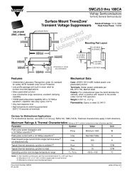
SMPS Capacitors<br />
SM Series<br />
CAPACITOR<br />
SUBSTRATE<br />
DIMENSIONS<br />
AT AMBIENT<br />
TEMPERATURE<br />
CAPACITOR<br />
BODY<br />
"J" LEADS<br />
"L" LEADS<br />
CAPACITOR<br />
BODY<br />
CAPACITOR<br />
SUBSTRATE<br />
Toper > Tamb CTE sub > CTE cap<br />
SUBSTRATE LINEAR<br />
DISPLACEMENT<br />
PUTS SOLDER JOINT<br />
AND CAPACITOR IN<br />
TENSION<br />
SOLDER LAND<br />
SOLDER<br />
FILLETS<br />
CAPACITOR<br />
SUBSTRATE<br />
Toper > Tamb CTE sub < CTE cap<br />
Figure 1. Linear Displacement Between<br />
Component and Substrate<br />
General Processing Guidelines<br />
Figure 2 shows the location of maximum stress in the solder<br />
joint due to positive and negative DCTE and linear displacement.<br />
CAPACITOR<br />
MAXIMUM STRESS<br />
SUBSTRATE<br />
SUBSTRATE LINEAR<br />
DISPLACEMENT<br />
PUTS SOLDER JOINT<br />
AND CAPACITOR IN<br />
COMPRESSION<br />
SOLDER<br />
FILLET<br />
SUBSTRATE<br />
Figure 3. “J” and “L” Leadframes Mounted on Capacitors to<br />
Relieve Stress<br />
Inductance<br />
Adding leadframes has a small impact on component inductance<br />
but this is the price that must be paid for reliable operation<br />
over temperature. Figure 4 shows typical leadframe inductance<br />
that is added for two lead standoff distances (0.020" and 0.050")<br />
versus the number of leads along one side of SupraCap TM which<br />
are specifically designed output filter capacitors for 1 MHz and<br />
above switchers. The actual inductance will be somewhat less<br />
because the leadframes flare out from the lead where the leadframe<br />
is attached to the capacitor body.<br />
0.4<br />
Stress for Toper > Tamb CTE sub > CTE cap<br />
Total Leadframe<br />
Inductance (nH)<br />
0.3<br />
0.2<br />
0.1<br />
0.020"<br />
Standoff<br />
0.050"<br />
Standoff<br />
CAPACITOR<br />
MAXIMUM STRESS<br />
SOLDER<br />
FILLET<br />
0<br />
5 10 15 20<br />
Number of leads on one side of Capacitor<br />
SUBSTRATE<br />
Stress for Toper > Tamb CTE sub < CTE cap<br />
Figure 2<br />
Stress Relief<br />
Leadframes on larger capacitor sizes (greater than 2225) must<br />
be used to minimize mechanical stress on the solder joints during<br />
temperature cycling which is normal operation for power<br />
supplies (figure 3). Failing solder joints increase both ESR and<br />
ESL causing an increase in ripple, noise and heat, accelerating<br />
failure.<br />
Layout<br />
Effective solder dams must be used to keep all molten solder<br />
on the solder lands during reflow or solder will migrate away<br />
from the land, causing opens or weak solder joints. High frequency<br />
output filters cannot use low power layout techniques<br />
such as necked down conductors because of the stringent<br />
inductance requirements.<br />
Figure 4. Number of Leads on One Side of Capacitor vs.<br />
Total Leadframe Inductance vs. Substrate Standoff Height<br />
Very high frequency switch mode power supplies place<br />
tremendous restrictions on output filter capacitors. In addition<br />
to handling high ripple current (low ESR), ESL must approach<br />
zero nano henrys, part must be truly surface mountable and be<br />
available in new configurations to be integrated into transmission<br />
lines to further reduce inductance with load currents<br />
greater than 40A at 1 MHz and as frequencies move above<br />
1-2 MHz.<br />
The total inductance is the sum of each side of the part where<br />
the inductance of one side is the parallel combination of each<br />
lead in the leadframe. That inductance is given by:<br />
L (nH) = 5x [In (2x) / (B+C) + 1/2]<br />
Where = lead length in inches<br />
In = natural log<br />
B+C = lead cross section in inches<br />
so L 1 (nH) = 2xL (nH) where L 1 is the total inductance of the leadframe.<br />
* Reference <strong>AVX</strong> Technical Information paper, “Processing Guidelines for<br />
SMPS Capacitors.”<br />
22
High Voltage SMPS Capacitors<br />
C0G Dielectric<br />
General<br />
Specifications<br />
Capacitance Range<br />
100 pF to 1.2 µF (25°C, 1.0±0.2 Vrms at<br />
1 KHz, for ≤100 pF use 1 MHz)<br />
Capacitance Tolerances<br />
±5%, ±10%, ±20%<br />
Operating Temperature Range<br />
-55°C to +125°C<br />
Temperature Characteristic<br />
0 ± 30 ppm/°C<br />
Voltage Ratings<br />
1000 Vdc thru 5000 Vdc (+125°C)<br />
Dissipation Factor<br />
0.15% max. (25°C, 1.0±0.2 Vrms at<br />
1 KHz, for ≤100 pF use 1 MHz)<br />
Insulation Resistance (+25°C, at 500V)<br />
100K MΩ min., or 1000 MΩ-µF min.,<br />
whichever is less<br />
Insulation Resistance (+125°C, at 500V)<br />
10K MΩ min., or 100 MΩ-µF min.,<br />
whichever is less<br />
Dielectric Strength<br />
120% rated voltage, 5 seconds<br />
Life Test<br />
100% rated and +125°C<br />
N1500<br />
General<br />
Specifications<br />
Capacitance Range<br />
100 pF to 1.9 µF (25°C, 1.0±0.2 Vrms at<br />
1 KHz.<br />
Capacitance Tolerances<br />
±5%, ±10%, ±20%<br />
Operating Temperature Range<br />
-55°C to +125°C<br />
Temperature Characteristic<br />
N1500 ±250 ppm/°C<br />
Voltage Ratings<br />
1000 Vdc thru 5000 Vdc (+125°C)<br />
Dissipation Factor<br />
0.15% max. (25°C, 1.0±0.2 Vrms at<br />
1 KHz.<br />
Insulation Resistance (+25°C, at 500V)<br />
100K MΩ min., or 1000 MΩ-µF min.,<br />
whichever is less<br />
Insulation Resistance (+125°C, at 500V)<br />
10K MΩ min., or 100 MΩ-µF min.,<br />
whichever is less<br />
Dielectric Strength<br />
120% rated voltage, 5 seconds<br />
Life Test<br />
100% rated and +125°C<br />
X7R Dielectric<br />
General<br />
Specifications<br />
Capacitance Range<br />
100 pF to 15 µF (25°C, 1.0±0.2 Vrms at<br />
1 KHz.<br />
Capacitance Tolerances<br />
±10%, ±20%, +80%, -20%<br />
Operating Temperature Range<br />
-55°C to +125°C<br />
Temperature Characteristic<br />
±15% (0 Vdc)<br />
Voltage Ratings<br />
1000 Vdc thru 5000 Vdc (+125°C)<br />
Dissipation Factor<br />
2.5% max. (25°C, 1.0±0.2 Vrms at<br />
1 KHz.<br />
Insulation Resistance (+25°C, at 500V)<br />
100K MΩ min., or 1000 MΩ-µF min.,<br />
whichever is less<br />
Insulation Resistance (+125°C, at 500V)<br />
10K MΩ min., or 100 MΩ-µF min.,<br />
whichever is less<br />
Dielectric Strength<br />
120% rated voltage, 5 seconds<br />
Life Test<br />
100% rated and +125°C<br />
HOW TO ORDER:<br />
<strong>AVX</strong> STYLES: HV01 THRU HV06<br />
HV 01 A C 10 M A N 650<br />
<strong>AVX</strong> Style Size Voltage Temperature Capacitance Capacitance Failure Termination Height<br />
See 1K = A Coefficient Code Tolerance Rate N = Straight Lead (.650 is std.<br />
dimen- 2K = G C0G = A (2 significant C0G: J = ±5% A = Does J = Leads max. thickness<br />
sions 3K = H X7R = C digits + no. K = ±10% not apply formed in see dimensions<br />
chart 4K = J N1500 = 4 of zeros) M = ±20% L = Leads chart ref. dim. A)<br />
5K = K 10 pF = 100 X7R: K = ±10% formed out<br />
100 pF = 101 M = ±20%<br />
1,000 pF = 102 Z = +80, -20%<br />
22,000 pF = 223 N1500: J = ±5%<br />
220,000 pF = 224 K = ±10%<br />
1 µF = 105 M = ±20%<br />
10 µF = 106<br />
100 µF = 107<br />
Note: Capacitors with X7R and Z5U Dielectrics are not intended for AC line filtering applications. Contact Plant for recommendations.<br />
23
High Voltage SMPS Capacitors<br />
Surface Mount and Thru Hole Series<br />
D<br />
E<br />
CHIP SEPARATION<br />
.010 TYP.<br />
.010 RAD. (TYP.)<br />
B A<br />
0.055±.010<br />
.070±.010<br />
.075±.025 (TYP.)<br />
0.250 MIN.<br />
0.020 TYP.<br />
0.100 TYP.<br />
C<br />
0.010 TYP.<br />
"J" STYLE LEADS<br />
.010 RAD. (TYP.)<br />
0.100 MAX.<br />
0.025 MIN.<br />
.070±.010<br />
.075±.025 (TYP.)<br />
"N" STYLE LEADS<br />
"L" STYLE LEADS<br />
DIMENSION CHART<br />
No. of leads<br />
Style A (max.) B (max.) C ±.025 D ±.025 E (max.) per side<br />
HV01 .650 .710 2.100 .415 2.160 4<br />
HV02 .650 .710 1.540 .800 1.600 8<br />
HV03 .650 .710 1.070 .415 1.130 4<br />
HV04 .650 .710 .400 .400 .440 4<br />
HV05 .650 .710 .250 .250 .300 3<br />
HV06 .650 .710 2.100 1.140 2.160 11<br />
Note: Dimensions A & B are max. dimensions for 5 chip stacks (.120 max. each chip).<br />
Maximum Capacitance Available Versus Style<br />
<strong>AVX</strong> Style HV01 HV02 HV03 HV04 HV05 HV06<br />
Max. Cap. (µF) 1KV 2KV 3KV 4KV 5KV 1KV 2KV 3KV 4KV 5KV 1KV 2KV 3KV 4KV 5KV 1KV 2KV 3KV 4KV 5KV 1KV 2KV 3KV 4KV 5KV<br />
C0G (NP0)<br />
N1500<br />
.430<br />
.700<br />
.120 .056 .031 .026<br />
.210 .092 .050 .042<br />
.610 .170 .079 .044 .037<br />
1.00 .290 .120 .072 .060<br />
.210 .065 .029 .015 .012<br />
.340 .100 .045 .025 .020<br />
.064 .020 .009 .0045 .0037<br />
.100 .033 .014 .0072 .0063<br />
.024 .0068 .0029 .0013 .0011<br />
.039 .011 .0050 .0022 .0018<br />
X7R<br />
5.50 1.30 .750 .330 .260 7.90 1.80 1.00 .470 .390 2.60 .690 .360 .160 .120 .820 .210 .110 .048 – .300 .070 .032 .014 –<br />
No. of Leads/side** 4 8 4 4 3 11<br />
Standard Max. Stack* 5 5 5 5 5 5<br />
* All capacitance values are in µF’s and are based on 5 chips stacked.<br />
** Based on 0.100" centers.<br />
Note: Contact factory for other voltage ratings.<br />
EXAMPLE OF HOW TO ORDER<br />
HV01 3KV X7R<br />
Maximum capacitance for 5 section unit is .75 µF (as seen in above table).<br />
This would be .15 µF per chip.<br />
Maximum capacitance for 1 chip (single) is .15 µF HV01HC154KAN120<br />
Maximum capacitance for 2 chips stacked is .30 µF HV01HC304KAN240<br />
Maximum capacitance for 3 chips stacked is .45 µF HV01HC454KAN360<br />
Maximum capacitance for 4 chips stacked is .60 µF HV01HC604KAN480<br />
Maximum capacitance for 5 chips stacked is .75 µF HV01HC754KAN650<br />
24<br />
1KV 2KV 3KV 4KV 5KV<br />
1.20 .330 .140 .092 .078<br />
1.90 .530 .230 .150 .130<br />
15.0 3.50 2.20 1.00 .850
High Voltage MLC Radials<br />
Application Information on High Voltage MLC Capacitors<br />
High value, low leakage and small size are difficult parameters to<br />
obtain in capacitors for high voltage systems. <strong>Olean</strong> <strong>Advanced</strong><br />
<strong>Products</strong>’ special high voltage MLC leaded capacitors meet these<br />
performance characteristics. The added advantage of these capacitors<br />
lies in special internal design minimizing the electric field stresses<br />
within the MLC. These special design criteria result in significant<br />
reduction of partial discharge activity within the dielectric and having,<br />
therefore, a major impact on long-term reliability of the product. The<br />
high voltage radial capacitors are conformally coated with high insulation<br />
resistance, high dielectric strength epoxy eliminating the possibility<br />
of arc flashover.<br />
The high voltage radial MLC designs exhibit low ESRs at high frequency.<br />
The same criteria governing the high voltage design carries<br />
the added benefits of extremely low ESR in relatively low (0.05 µF to<br />
0.005 µF) capacitance and small packages. These capacitors are<br />
designed and are ideally suited for applications such as snubbers in<br />
high frequency power converters, resonators in SMPS, and high voltage coupling/DC blocking.<br />
Also because these MLC’s are designed for high voltage applications, as input resonator capacitors they are well safeguarded<br />
against transient requirements.<br />
High voltage chips are available with voltage ratings greater or equal to 600 volts in EIA standard sizes 1808 and larger. For full<br />
listing of high voltage chip capacitors please refer to pages 29 and 30.<br />
C0G Dielectric<br />
General Specifications<br />
Capacitance Range<br />
100 pF to .15 µF (1.0 Vrms, 1 KHz)<br />
Capacitance Tolerances<br />
±5%, ±10%, ±20%<br />
Operating Temperature Range<br />
-55°C to +125°C<br />
Temperature Characteristic<br />
0 ± 30 ppm/°C<br />
Voltage Ratings<br />
1000 Vdc thru 5000 Vdc (+125°C)<br />
Dissipation Factor<br />
0.15% max. (+25°C)<br />
1.0 Vrms, 1 KHz<br />
Insulation Resistance (+25°C, at 500V)<br />
100K MΩ min. or 1000 MΩ-µF min.,<br />
whichever is less<br />
Insulation Resistance (+125°C, at 500V)<br />
10K MΩ min., or 100 MΩ-µF min.,<br />
whichever is less<br />
Dielectric Strength<br />
120% rated voltage, 5 seconds<br />
Life Test<br />
100% rated and +125°C<br />
X7R Dielectric<br />
General Specifications<br />
Capacitance Range<br />
100 pF to 2.2 µF (1.0 Vrms, 1 KHz)<br />
Capacitance Tolerances<br />
±10%, ±20%, +80%, -20%<br />
Operating Temperature Range<br />
-55°C to +125°C<br />
Temperature Characteristic<br />
±15% (0 Vdc)<br />
Voltage Ratings<br />
1000 Vdc thru 5000 Vdc (+125°C)<br />
Dissipation Factor<br />
2.5% max. (+25°C, 1.0 Vrms, 1 KHz)<br />
Insulation Resistance (+25°C, at 500V)<br />
100K MΩ min., or 1000 MΩ-µF min.,<br />
whichever is less<br />
Insulation Resistance (+125°C, at 500V)<br />
10K MΩ min., or 100 MΩ-µF min.,<br />
whichever is less<br />
Dielectric Strength<br />
120% rated voltage, 5 seconds<br />
Life Test<br />
100% rated and +125°C<br />
25
High Voltage MLC Radials<br />
L<br />
T<br />
H<br />
1.25<br />
MIN<br />
.025 ±.002 (22 GA)<br />
S<br />
High Voltage Radial Lead<br />
<strong>AVX</strong> Styles: SV01 thru SV12<br />
How to Order:<br />
SV01 A A 102 K A A<br />
<strong>AVX</strong> Voltage Temperature Capacitance Code Capacitance A = Does A = Does<br />
Style 1000V = A Coefficient (2 significant digits + no. Tolerance not apply not apply<br />
2000V = G C0G = A of zeros) C0G: J = ±5%<br />
3000V = H X7R = C Examples: K = ±10%<br />
4000V = J 10 pF = 100 M = ±20%<br />
5000V = K 100 pF = 101 X7R: K = ±10%<br />
1,000 pF = 102 M = ±20%<br />
22,000 pF = 223 Z = +80 -20%<br />
220,000 pF = 224<br />
1 µF = 105<br />
Note: Capacitors with X7R and Z5U Dielectrics are not intended for AC line filtering applications. Contact Plant for recommendations.<br />
DIMENSION CHART<br />
<strong>AVX</strong> Style Length (L) max Height (H) max Thickness (T) max Lead Spacing±.030 (S)<br />
SV01 .250 .220 .200 .170<br />
SV02 .320 .280 .200 .220<br />
SV03 .370 .300 .200 .275<br />
SV04 .450 .220 .200 .300<br />
SV05 .470 .400 .200 .375<br />
SV06 .550 .280 .200 .400<br />
SV07 .570 .500 .200 .475<br />
SV08 .670 .600 .200 .575<br />
SV09 .770 .720 .200 .675<br />
SV10 1.050 .500 .200 .900<br />
SV11 1.250 .600 .200 1.100<br />
SV12 1.450 .720 .200 1.300<br />
26
High Voltage MLC Radials<br />
Maximum Capacitance Value<br />
C0G<br />
Style 1000V 2000V 3000V 4000V 5000V<br />
SV01 1000pF 180pF 82pF — —<br />
SV02 3300pF 680pF 270pF 150pF 100pF<br />
SV03 5600pF 1200pF 470pF 270pF 180pF<br />
SV04 2200pF 470pF 180pF 100pF 68pF<br />
SV05 .015µF 3300pF 1200pF 680pF 470pF<br />
SV06 .0068µF 1500pF 560pF 330pF 220pF<br />
SV07 .027µF 5600pF 2200pF 1200pF 820pF<br />
SV08 .039µF .01µF 3900pF 2200pF 1500pF<br />
SV09 .068µF .015µF 6800pF 3900pF 2700pF<br />
SV10 .056µF .012µF 5600pF 3300pF 2200pF<br />
SV11 .082µF .022µF .0082µF 4700pF 3300pF<br />
SV12 .15µF .033µF .015µF 8200pF 5600pF<br />
X7R<br />
SV01 .012µF 1500pF — — —<br />
SV02 .047µF 5600pF 2700pF — —<br />
SV03 .082µF .01µF 4700pF 1800pF —<br />
SV04 .033µF 3900pF 1800pF 820pF —<br />
SV05 .22µF .027µF .012µF 4700pF —<br />
SV06 .10µF .012µF 6800pF 2700pF 1200pF<br />
SV07 .39µF .047µF .027µF .01µF 6800pF<br />
SV08 .68µF .082µF .047µF .018µF .012µF<br />
SV09 1.00µF .12µF .068µF .027µF .018µF<br />
SV10 .82µF .10µF .056µF .022µF .018µF<br />
SV11 1.2µF .18µF .10µF .039µF .027µF<br />
SV12 2.20µF .27µF .15µF .056µF .033µF<br />
Note: Contact factory for other voltage ratings or values.<br />
<strong>AVX</strong> is qualified to the following DSCC drawings.<br />
Specification # Description Capacitance Range<br />
87046 C0G-1000 VDC 10 pF - 0.025 µF<br />
87043 X7R-1000 VDC 100 pF - 0.47 µF<br />
87040 X7R-2000 VDC 100 pF - 0.22 µF<br />
87114 C0G-3000 VDC 10 pF - 8200 pF<br />
87047 X7R-3000 VDC 100 pF - 0.1 µF<br />
87076 C0G-4000 VDC 10 pF - 6800 pF<br />
89044 X7R-4000 VDC 100 pF - 0.056 µF<br />
87077 C0G-5000 VDC 10 pF - 5600 pF<br />
87070 X7R-5000 VDC 100 pF - 0.033 µF<br />
87081 X7R-10000 VDC 470 pF - 0.01 µF<br />
These specifications require group A and B testing per<br />
C0G - MIL-C-20<br />
X7R - MIL-C-39014<br />
27
MLC Chip Capacitors<br />
Basic Construction<br />
A multilayer ceramic (MLC) capacitor is a monolithic block<br />
of ceramic containing two sets of offset, interleaved planar<br />
electrodes that extend to two opposite surfaces of<br />
the ceramic dielectric. This simple structure requires a<br />
considerable amount of sophistication, both in material<br />
and in manufacture, to produce it in the quality and quantities<br />
needed in today’s electronic equipment.<br />
Terminations<br />
Ceramic Layer<br />
Electrode<br />
• Standard Nickel Barrier<br />
• Leach resistance to 90 seconds at 260°C<br />
• Solder plated for dimensional control<br />
End Terminations<br />
Terminated<br />
Edge<br />
Terminated<br />
Edge<br />
Margin<br />
Electrodes<br />
Quality Statement<br />
<strong>AVX</strong>’s focus is customer satisfaction – Customer satisfaction in the broadest sense: <strong>Products</strong>, service, price,<br />
delivery, technical support, and all the aspects of a business that impact you, the customer.<br />
Our long term strategy is for continuous improvement which is defined by our Quality Vision 2000. This is a total quality<br />
management system developed by and supported by <strong>AVX</strong> corporate management. The foundation of QV2000 is built upon<br />
military and commercial standards and systems including ISO 9001. QV2000 is a natural extension of past quality efforts with<br />
world class techniques for ensuring a total quality environment to satisfy our customers during this decade and into the<br />
21st century.<br />
As your components supplier, we invite you to experience the quality, service, and commitment of <strong>AVX</strong>.<br />
28
MLC High Voltage Chips<br />
For 600V to 5,000V Application<br />
High value, low leakage and small size are difficult parameters<br />
to obtain in capacitors for high voltage systems. <strong>AVX</strong>’s special<br />
high voltage MLC chips capacitors meet these performance<br />
characteristics and are designed for applications such as<br />
snubbers in high frequency power converters, resonators in<br />
SMPS, and high voltage coupling/DC blocking. These high<br />
voltage chip designs exhibit low ESRs at high frequencies.<br />
Larger physical sizes than normally encountered chips are<br />
used to make high voltage chips. These larger sizes require<br />
that special precautions be taken in applying these chips in<br />
surface mount assemblies. This is due to differences in the<br />
coefficient of thermal expansion (CTE) between the substrate<br />
materials and chip capacitors.<br />
How to Order:<br />
1808 A A 271 K A 1 1A<br />
<strong>AVX</strong> Voltage Temperature Capacitance Code Capacitance Failure Termination<br />
Style 600V = C Coefficient (2 significant digits Tolerance Rate 1 = Pd/Ag<br />
1206 1000V = A C0G = A + no. of zeros) C0G: J = ±5% A = Not T = NiGuard<br />
1210 1500V = S X7R = C Examples: K = ±10% Applicable Nickel<br />
1808 2000V = G 10 pF = 100 M = ±20% Barrier<br />
1812 2500V = W 100 pF = 101 X7R: K = ±10% Solder<br />
1825 3000V = H 1,000 pF = 102 M = ±20% Plate<br />
2225 4000V = J 22,000 pF = 223 Z = +80% (See Note 1)<br />
3640 5000V = K 220,000 pF = 224 -20%<br />
1 µF = 105<br />
Note 1: Styles 1825, 2225, & 3640 are available with “N”, “L” or “J” leads as seen on page 9.<br />
“V” denotes uncoated leaded units similar to SM0 product.<br />
“W” denotes leaded epoxy coated units similar to SM5 product.<br />
IE 1825AA103KAV00J would be uncoated leaded part with “J” style leads.<br />
Note 2: Style 1808 cannot have the marking oriented in tape & reel packaging due to square<br />
cross-section of chip.<br />
Packaging/Marking*<br />
ME = 7" Reel<br />
Embossed<br />
Tape/Marked<br />
RE = 13" Reel<br />
Embossed<br />
Tape/Marked<br />
BE = Bulk/Marked<br />
1A = 7" Reel<br />
Embossed<br />
Tape/Unmarked<br />
3A = 13" Reel<br />
Embossed<br />
Tape/Unmarked<br />
9A = Bulk/Unmarked<br />
*Unmarked product is standard.<br />
Note: Capacitors with X7R and Z5U Dielectrics are not intended for AC line filtering applications. Contact Plant for recommendations.<br />
L<br />
W<br />
T<br />
DIMENSIONS<br />
SIZE 1206 1210 1808 1812 1825 2225 3640<br />
(L) Length inches .126 ± .008 .126 ± .008 .180 ± .010 .177 ± .012 .177 ± .012 .225 ±.010 .360 ± .010<br />
(mm) (3.20 ± .20) (3.20 ± .20) (4.57 ± .25) (4.50 ± .3) (4.50 ± .3) (5.72 ± .25) (9.14 ± .25)<br />
(W) Width inches .063 ± .008 .098 ± .008 .080 ± .010 .126 ± .008 .252 ± .012 .250 ± .010 .400 ± .010<br />
(mm) (1.60 ± .20) .(2.50 ± .20) (2.03 ± .25) (3.20 ± 0.2) (6.40 ± .3) (6.35 ± .25) (10.2 ± .25)<br />
(T) Thickness inches .060 .067 .100 .100 .100 .100 .100<br />
Max. (mm) (1.52) (1.70) (2.54) (2.54) (2.54) (2.54) (2.54)<br />
(t) terminal min. .010 (.25) .010 (.25) .010 (.25) .010 (.25) .010 (.25) .010 (.25) .030 (.76)<br />
in. (mm) max. .030 (.75) .030 (.75) .040 (1.02) .040 (1.02) .040 (1.02) .040 (1.02) .060 (1.52)<br />
t<br />
29
MLC High Voltage Chips<br />
For 600V to 5000V Applications<br />
C0G Dielectric<br />
Performance Characteristics<br />
Capacitance Range 10 pF to .047 µF<br />
(25°C, 1.0 ±0.2 Vrms at 1kHz, for ≤ 1000pF use 1 MHz)<br />
Capacitance Tolerances ±5%, ±10%, ±20%<br />
Dissipation Factor<br />
Operating Temperature Range<br />
Temperature Characteristic<br />
Voltage Ratings<br />
Insulation Resistance (+25°C, at 500 VDC)<br />
Insulation Resistance (+125°C, at 500 VDC)<br />
Dielectric Strength<br />
C0G Maximum Capacitance Values<br />
0.1% max. (+25°C, 1.0 ±0.2 Vrms, 1kHz, for ≤ 1000pF use 1 MHz)<br />
–55°C to +125°C<br />
0 ±30 ppm/°C (0 VDC)<br />
600, 1000, 1500, 2000, 2500, 3000, 4000 & 5000 VDC (+125°C)<br />
100K MΩ min. or 1000 MΩ - µF min., whichever is less<br />
10K MΩ min. or 100 MΩ - µF min., whichever is less<br />
120% rated voltage for 5 seconds at 50 mamp max. current<br />
VOLTAGE 1206 1210 1808 1812 1825 2225 3640<br />
600 470 pF 1200 pF 3300 pF 5600 pF .012 µF .018 µF .047 µF<br />
1000 180 pF 470 pF 1200 pF 2200 pF 5600 pF 8200 pF .018 µF<br />
1500 — — 330 pF 560 pF 1500 pF 1800 pF 5600 pF<br />
2000 — — 270 pF 470 pF 1200 pF 1500 pF 4700 pF<br />
2500 — — 100 pF 220 pF 560 pF 820 pF 2700 pF<br />
3000 — — 82 pF 180 pF 470 pF 680 pF 2200 pF<br />
4000 — — — — — — 1000 pF<br />
5000 — — — — — — 680 pF<br />
X7R Dielectric<br />
Performance Characteristics<br />
Capacitance Range<br />
100 pF to 0.56 µF (25°C, 1.0 ±0.2 Vrms at 1kHz)<br />
Capacitance Tolerances ±10%; ±20%; +80%, -20%<br />
Dissipation Factor<br />
Operating Temperature Range<br />
Temperature Characteristic<br />
Voltage Ratings<br />
Insulation Resistance (+25°C, at 500 VDC)<br />
Insulation Resistance (+125°C, at 500 VDC)<br />
Dielectric Strength<br />
2.5% max. (+25°C, 1.0 ±0.2 Vrms, 1kHz)<br />
–55°C to +125°C<br />
±15% (0 VDC)<br />
600, 1000, 1500, 2000, 2500, 3000 & 4000 VDC (+125°C)<br />
100K MΩ min. or 1000 MΩ - µF min., whichever is less<br />
10K MΩ min. or 100 MΩ - µF min., whichever is less<br />
120% rated voltage for 5 seconds at 50 mamp max. current<br />
X7R Maximum Capacitance Values<br />
VOLTAGE 1206 1210 1808 1812 1825 2225 3640<br />
600 6800 pF .018 µF .039 µF .068 µF .15 µF .22 µF .56 µF<br />
1000 1000 pF 2700 pF .015 µF .027 µF .068 µF .082 µF .22 µF<br />
1500 — — 2700 pF 5600 pF .012 µF .018 µF .056 µF<br />
2000 — — 1500 pF 2700 pF 6800 pF .010 µF .027 µF<br />
2500 — — 1200 pF 2200 pF 5600 pF 8200 pF .022 µF<br />
3000 — — — — — 4700 pF .018 µF<br />
4000 — — — — — — 5600 pF<br />
30
MLC High Voltage Chips<br />
Packaging of Chip Components<br />
Automatic Insertion Packaging<br />
Tape & Reel Quantities<br />
All tape and reel specifications are in compliance with EIA481.<br />
8mm 12mm 24mm<br />
Embossed Only 1206 1808 1812, 1825 3640<br />
1210 2225<br />
Qty. per Reel/7" Reel 2000 2000 1000 N/A<br />
Qty. per Reel/13" Reel 10,000 4000 3000 1000<br />
Reel Dimensions<br />
Tape A B*<br />
C<br />
D* N<br />
W<br />
W 2 1 W Size Max. Min. Min. Min. Max.<br />
3<br />
8mm<br />
7.9 Min.<br />
+1.0<br />
330 1.5 13.0±0.20 20.2 50 8.4 -0.0 14.4 (.311)<br />
(12.992) (.059) (.512±.008) (.795) (1.969) (.331 +.060 ) (.567) 10.9 Max.<br />
+0.0<br />
(.429)<br />
11.9 Min.<br />
+2.0<br />
12mm 330 1.5 13.0±0.20 20.2 50 12.4 –0.0 18.4 (.469)<br />
(12.992) (.059) (.512±.008) (.795) (1.969) (.488 +.076 –0.0 ) (.724) 15.4 Max.<br />
(.607)<br />
Metric dimensions will govern.<br />
23.9 Min.<br />
+0.5 +2.0<br />
English 24mm measurements 360 rounded and for 1.5 reference only. 13.0 -0.2 20.2 60 24.4 –0.00 30.4 (.941)<br />
(14.173) (.059) (.512 +.020 -.008) (.795) (2.362) (.961 +.070 –0.00) (1.197) 27.4 Max.<br />
(1.079)<br />
31
Tip & Ring<br />
Multilayer Ceramic Chip Capacitors<br />
<strong>AVX</strong>’s “Tip & Ring”, or “ringer”, Multilayer Ceramic Chip<br />
Capacitors are designed as a standard telecom filter to block<br />
-48 Volts DC telephone line voltage and pass subscriber’s AC<br />
signal pulse (16 to 25Hz, 70 to 90Vrms). The typical ringing<br />
signal is shown in figure 1. The ringer capacitor replaces large<br />
leaded film capacitors and are ideal for telecom/modem applications.<br />
Using <strong>AVX</strong>’s “Tip & Ring” capacitors not only saves<br />
valuable real estate on the board and reduces the weight of<br />
overall product, but also features standard surface mounting<br />
capabilities, which is critical to new and compact designs.<br />
250V<br />
Tip & Ring<br />
The <strong>AVX</strong> “Tip & Ring” capacitors are offered in three standard<br />
EIA sizes and standard values. They offer excellent high frequency<br />
performance, low ESR and improved temperature<br />
performance over film capacitors.<br />
0<br />
-48V<br />
-250V<br />
-400ms 200ms/div 1.6s<br />
Note: These capacitors are larger than standard surface<br />
mount components and are intended for IR, hot plate (belt)<br />
and convection reflow or vapor phase reflow (VPR) processes.<br />
For recommended soldering profiles reference <strong>AVX</strong>’s<br />
Technical Paper: “Parameters Important for Surface Mount<br />
Applications of Multilayer Ceramic Capacitors” on <strong>AVX</strong>’s<br />
World Wide Web site: http://www.avxcorp.com<br />
Figure 1<br />
GENERAL SPECIFICATIONS<br />
Capacitance Range<br />
0.1µF to 1.0µF (25°C, 1.0 ± 0.2Vrms at 1KHz)<br />
Capacitance Tolerances ±10%, ±20%<br />
Dissipation Factor<br />
2.5% max. (25°C, 1.0 ± 0.2Vrms at 1 KHz)<br />
Temperature Characteristic Y5R ±15% (0VDC)<br />
Voltage Rating<br />
Tip and Ring Application<br />
IR (25°C, at 100VDC) 1000 MΩ-µF min.<br />
Dielectric Strength<br />
300VDC for 5 seconds at 50mA max. current<br />
Life Test Capabilities 1000 hrs, 200 VDC at 85°C<br />
Humidity Test<br />
(MIL-C-55681)<br />
Resistance to Soldering Heat (MIL-C-55681)<br />
Solderability 90% min. coverage (MIL-STD-202, Method 208)<br />
32
Tip & Ring<br />
Multilayer Ceramic Chip Capacitors<br />
HOW TO ORDER:<br />
1812<br />
<strong>AVX</strong><br />
Style<br />
1812<br />
1825<br />
2225<br />
P 2<br />
Voltage Temp<br />
Coefficient<br />
Y5R<br />
Tip & Ring<br />
Application<br />
104<br />
Capacitance<br />
Code<br />
(2 significant<br />
digits + no. of<br />
zeros)<br />
Examples:<br />
1,000 pF = 102<br />
22,000 pF = 223<br />
220,000 pF = 224<br />
1 uF = 105<br />
K<br />
Capacitance<br />
Tolerance<br />
K = ± 10%<br />
M = ± 20%<br />
A<br />
Failure<br />
Rate<br />
A = Not<br />
Applicable<br />
1<br />
Termination<br />
1 = Pd/Ag<br />
T = Nickel<br />
Barrier<br />
Solder<br />
Plate<br />
1<br />
Packaging<br />
1 = 7” Reel<br />
Embossed<br />
Tape<br />
3 = 13” Reel<br />
Embossed<br />
Tape<br />
9 = Bulk<br />
A<br />
Special<br />
Code<br />
A =<br />
Unmarked<br />
DIMENSIONS OF<br />
TIP & RING CAPACITORS<br />
Size 1812 1825 2225<br />
L<br />
➔<br />
➔<br />
W<br />
➔<br />
(L) Length<br />
(W) Width<br />
inches<br />
(mm)<br />
inches<br />
(mm)<br />
.177 ± .012<br />
(4.50 ± .3)<br />
.126 ± .008<br />
(3.20 ± .2)<br />
.177 ± .012<br />
(4.50 ± .3)<br />
.252 ± .012<br />
(6.40 ± .3)<br />
.225 ± .010<br />
(5.72 ± .25)<br />
.250 ± .010<br />
(6.35 ± .25)<br />
➔<br />
➔<br />
T<br />
➔<br />
➔<br />
➔<br />
t<br />
(t) terminal<br />
in. (mm)<br />
min.<br />
max.<br />
.010 (.25)<br />
.040 (1.02)<br />
.010 (.25)<br />
.040 (1.02)<br />
.010 (.25)<br />
.040 (1.02)<br />
PRODUCT OFFERING<br />
SIZE CAPACITANCE (T) THICKNESS<br />
µF (MAX.)<br />
1812<br />
1825<br />
0.10<br />
0.22<br />
0.33<br />
0.47<br />
0.055 (1.40)<br />
0.075 (1.91)<br />
0.055 (1.40)<br />
0.070 (1.78)<br />
2225 1.00<br />
0.100 (2.54)<br />
33
Single-In-Line Packages (SIP)<br />
Capacitor Arrays<br />
SIP-style, MLC ceramic capacitor arrays are Single-In-Line,<br />
conformally coated packages. These capacitor networks<br />
incorporate multiple capacitors into a single substrate and,<br />
therefore, offer excellent TC tracking. The utilization of SIP<br />
capacitor arrays minimizes board real estate and reduces<br />
component count in the assembly. Various circuit configurations<br />
and capacitance/voltage values are available.<br />
.850 MAX .135 MAX<br />
.015<br />
MIN<br />
.300 MAX<br />
.115 MIN<br />
.060<br />
MAX<br />
.100<br />
±.010*<br />
.058<br />
±.012<br />
.018 +.004<br />
-.002<br />
.010 +.003<br />
-.000<br />
*Lead spacing .100 ± .010 noncumulative<br />
1 2 3 4 5 6 7 8 1 2 3 4 5 6 7 8<br />
7 CAPACITOR SECTIONS 4 CAPACITOR SECTIONS<br />
1 GROUND LEAD<br />
CIRCUIT DIAGRAM “A”<br />
CIRCUIT DIAGRAM “B”<br />
<strong>AVX</strong> IS QUALIFIED TO THE FOLLOWING DSCC DRAWINGS<br />
SPECIFICATION # DESCRIPTION CIRCUIT CAPACITANCE RANGE<br />
87112 BX-100 VDC A 1000 pF - 0.1 µF<br />
87116 C0G-100 VDC A 10 pF - 820 pF<br />
87122 BX-100 VDC B 1000 pF - 0.1 µF<br />
89086 C0G-100 VDC B 10 pF - 820 pF<br />
34
Discoidal MLC<br />
Application Information on Discoidal<br />
OD*<br />
ID<br />
T Max.<br />
Lowest Capacitance Impedances to Ground<br />
A discoidal MLC capacitor has very low impedance associated with its ground<br />
path since the signal is presented with a multi-directional path. These electrode<br />
paths, which can be as many as 100, allow for low ESR and ESL which are the<br />
major elements in impedance at high frequencies.<br />
The assembled discoidal element or feed-thru allows signal to be fed in through<br />
a chassis or bulkhead, conditioned as it passes through the discoidal, and isolated<br />
by the chassis and discoidal from the original signal. An example of this application<br />
would be in an AFT circuit where the AC noise signal would be required to<br />
be stripped from the DC control signal. Other applications include single line<br />
EMI/RFI suppression, L-C filter construction, and coaxial shield bypass filtering.<br />
The shape of the discoidal lends itself to filter construction. The short length allows<br />
compact construction where L-C construction is desired.<br />
The size freedom associated with this element allows almost any inside/outside<br />
diameter combination. By allowing the inside diameter to equal the center insulator<br />
diameter of a coaxial signal line and special termination techniques, this device<br />
will allow bypass filtering of a floating shield to ground.<br />
Discoidal capacitors are available in three temperature coefficients (NP0, X7R,<br />
Z5U) and a variety of sizes, the most standard of which appear in this catalog.<br />
These surfaces are metallized<br />
.005 in. minimum wide except<br />
for DC61, DC26 and DC63<br />
where metallized surfaces<br />
are 0.005" maximum.<br />
*Tol. = + - .010" or 3%, whichever is greater<br />
Electrical Specifications<br />
Temperature Coefficient<br />
C0G: A Temperature Coefficient — 0 ±30 ppm/°C, -55° +125°C<br />
X7R: C Temperature Coefficient — ±15%, -55° to +125°C<br />
Z5U: E Temperature Coefficient — +22, -56°, +10° to +85°C<br />
Capacitance Test (MIL-STD-202 Method 305)<br />
C0G: 25°C, 1.0±0.2 Vrms at 1KHz, for ≤100pF use 1 MHz<br />
X7R: 25°C, 1.0±0.2 Vrms at 1KHz<br />
Z5U: 25°C, 0.5 Vrms max at 1KHz<br />
Dissipation Factor 25°C<br />
C0G: .15% Max @ 25°C, 1.0±0.2 Vrms at 1KHz, for ≤100pF use 1 MHz<br />
X7R: 2.5% Max @ 25°C, 1.0±0.2 Vrms at 1KHz<br />
Z5U: 3.0% Max @ 25°C, 0.5 Vrms max at 1KHz<br />
Insulation Resistance 25°C (MIL-STD-202 Method 302)<br />
C0G and X7R: 100K MΩ or 1000 MΩ-µF whichever is less.<br />
Z5U: 10K MΩ or 1000 MΩ-µF whichever is less.<br />
HOW TO ORDER:<br />
INSERTION LOSS<br />
-80<br />
0 100 200 300 400 500 600 700 800 900 1000<br />
f (MHz)<br />
Dielectric Withstanding Voltage 25°C (Flash Test)*<br />
C0G and X7R: 250% rated voltage for 5 seconds with 50 mA max<br />
charging current. 500V rated units will be tested at 750 VDC<br />
Z5U: 200% rated voltage for 5 seconds with 50 mA max charging<br />
current.<br />
Life Test (1000 hrs)<br />
C0G and X7R: 200% rated voltage at +125°C (500 Volt Units<br />
@ 600 VDC)<br />
Z5U: 150% rated voltage at +85°C<br />
Moisture Resistance (MIL-STD-202 Method 106)<br />
C0G, X7R, Z5U: Ten cycles with no voltage applied.<br />
Thermal Shock (MIL-STD-202 Method 107, Condition A)<br />
Immersion Cycling (MIL-STD-202 Method 104, Condition B)<br />
DC61 5 A 561 K A 5 1 06<br />
<strong>AVX</strong> Voltage Temperature Capacitance Code Capacitance Failure Termination Inside Maximum<br />
Style 50V = 5 Coefficient (2 significant digits Tolerance Rate 5 = Silver Diameter Thickness<br />
See Pages 100V = 1 C0G = A + no. of zeros) NP0: J = ±5% A = Not (<strong>AVX</strong> Standard) See Pages 06 = .060 inches<br />
36-38 200V = 2 X7R = C Examples: K = ±10% applicable 36-38 (1.52)<br />
500V = 7 Z5U = E 10 pF = 100 M = ±20% 10 = .100 inches<br />
100 pF = 101 X7R: K = ±10% (2.54)<br />
1,000 pF = 102 M = ±20%<br />
22,000 pF = 223 Z5U: M = ±20%<br />
220,000 pF = 224 Z = +80 -20%<br />
1 µF = 105 P = GMV<br />
(dB)<br />
0<br />
-10<br />
-20<br />
-30<br />
-40<br />
-50<br />
-60<br />
-70<br />
SINGLE CHIP<br />
DISCOIDAL<br />
For dimensions, voltages or values not specified, please consult factory.<br />
35
Discoidal C0G (NP0)<br />
Size and Capacitance Specifications<br />
EIA<br />
Characteristic<br />
C0G (NP0)<br />
Dimensions: Inches (Millimeters)<br />
<strong>AVX</strong> Style DC61 DC26 DC63 DC04 DC65 DC66 DC67 DC69 DC32 DC70 DC02 DC71 DC05 DC73 DC72<br />
Outside .100 .135 .150 .190 .210 .235 .265 .320 .335 .350 .370 .385 .500 .600 .640<br />
Diameter (OD)* (2.54) (3.43) (3.81) (4.83) (5.33) (5.97) (6.73) (8.13) (8.51) (8.89) (9.40) (9.78) (12.70) (15.24) (16.26)<br />
Thickness .060 .060 .060 .100 .100 .100 .100 .100 .100 .100 .100 .100 .100 .100 .100<br />
Maximum<br />
(T)<br />
(1.52) (1.52) (1.52) (2.54) (2.54) (2.54) (2.54) (2.54) (2.54) (2.54) (2.54) (2.54) (2.54) (2.54) (2.54)<br />
Inside 1,2 1,2,3 1,2,3,4 1,2,3 1,2,3,4 1,2,3,4 1,2,3,4 1,2,3,4 1,2,3,4 1,2,3,4 1,2,3,4 1,2,3,4 1,2,3,4 1,2,3,4 1,2,3,4<br />
Diameter No.** (ID) 5,6,7 5,6,7 5,6,7 5,6,7 5,6,7 5,6,7 5,6,7 5,6,7 5,6,7 5,6,7 5,6,7<br />
Voltage **<br />
500<br />
200<br />
100<br />
50<br />
500<br />
200<br />
100<br />
50<br />
500<br />
200<br />
100<br />
50<br />
500<br />
200<br />
100<br />
50<br />
500<br />
200<br />
100<br />
50<br />
500<br />
200<br />
100<br />
50<br />
500<br />
200<br />
100<br />
50<br />
500<br />
200<br />
100<br />
50<br />
500<br />
200<br />
100<br />
50<br />
500<br />
200<br />
100<br />
50<br />
500<br />
200<br />
100<br />
50<br />
500<br />
200<br />
100<br />
50<br />
500<br />
200<br />
100<br />
50<br />
500<br />
200<br />
100<br />
50<br />
500<br />
200<br />
100<br />
50<br />
cap. in pF 10<br />
12<br />
15<br />
18<br />
22<br />
27<br />
33<br />
39<br />
47<br />
56<br />
68<br />
82<br />
100<br />
120<br />
150<br />
180<br />
220<br />
270<br />
330<br />
390<br />
470<br />
560<br />
680<br />
820<br />
1000<br />
1200<br />
1500<br />
1800<br />
2200<br />
2700<br />
3300<br />
3900<br />
4700<br />
5600<br />
6800<br />
8200<br />
10,000<br />
12,000<br />
15,000<br />
18,000<br />
22,000<br />
27,000<br />
33,000<br />
39,000<br />
47,000<br />
56,000<br />
68,000<br />
82,000<br />
100,000<br />
120,000<br />
150,000<br />
180,000<br />
220,000<br />
270,000<br />
330,000<br />
390,000<br />
470,000<br />
560,000<br />
680,000<br />
*Outside Diameter:<br />
Tolerance is ±.010 or 3% whichever is greater<br />
1 = .025 +.005 (.635 +.127 )<br />
-.002 -.051<br />
2 = .030 +.005 (.762 +.127 )<br />
-.002 -.051<br />
3 = .036 +.005 (.914 +.127 )<br />
-.002 -.051<br />
4 = .042 +.005 (1.07 +.127 )<br />
-.002 -.051<br />
5 = .050±.005 (1.27±.127)<br />
6 = .060±.005 (1.52±.127)<br />
7 = .068±.005 (1.73±.127)<br />
36
Discoidal X7R<br />
Size and Capacitance Specifications<br />
Dimensions: Inches (Millimeters)<br />
EIA<br />
Characteristic<br />
X7R<br />
<strong>AVX</strong> Style DC61 DC26 DC63 DC04 DC65 DC66 DC67 DC69 DC32 DC70 DC02 DC71 DC05 DC73 DC72<br />
Outside .100 .135 .150 .190 .210 .235 .265 .320 .335 .350 .370 .385 .500 .600 .640<br />
Diameter (OD)* (2.54) (3.43) (3.81) (4.83) (5.33) (5.97) (6.73) (8.13) (8.51) (8.89) (9.40) (9.78) (12.70) (15.24) (16.26)<br />
Thickness<br />
Maximum<br />
(T)<br />
.060<br />
(1.52)<br />
.060<br />
(1.52)<br />
.060<br />
(1.52)<br />
.100<br />
(2.54)<br />
.100<br />
(2.54)<br />
.100<br />
(2.54)<br />
.100<br />
(2.54)<br />
.100<br />
(2.54)<br />
.100<br />
(2.54)<br />
.100<br />
(2.54)<br />
.100<br />
(2.54)<br />
.100<br />
(2.54)<br />
.100<br />
(2.54)<br />
.100<br />
(2.54)<br />
.100<br />
(2.54)<br />
Inside 1,2 1,2,3 1,2,3,4 1,2,3 1,2,3,4 1,2,3,4 1,2,3,4 1,2,3,4 1,2,3,4 1,2,3,4 1,2,3,4 1,2,3,4 1,2,3,4 1,2,3,4 1,2,3,4<br />
Diameter No.** (ID) 5,6,7 5,6,7 5,6,7 5,6,7 5,6,7 5,6,7 5,6,7 5,6,7 5,6,7 5,6,7 5,6,7<br />
Voltage **<br />
cap. in pF 56<br />
68<br />
82<br />
100<br />
120<br />
150<br />
180<br />
220<br />
270<br />
330<br />
390<br />
470<br />
560<br />
680<br />
820<br />
1000<br />
1200<br />
1500<br />
1800<br />
2200<br />
2700<br />
3300<br />
3900<br />
4700<br />
5600<br />
6800<br />
8200<br />
10,000<br />
12,000<br />
15,000<br />
18,000<br />
22,000<br />
27,000<br />
33,000<br />
39,000<br />
47,000<br />
56,000<br />
68,000<br />
82,000<br />
100,000<br />
120,000<br />
150,000<br />
180,000<br />
220,000<br />
270,000<br />
330,000<br />
390,000<br />
470,000<br />
560,000<br />
680,000<br />
820,000<br />
1.0 µF<br />
1.2 µF<br />
1.5 µF<br />
1.8 µF<br />
2.2 µF<br />
2.7 µF<br />
3.3 µF<br />
3.9 µF<br />
6.8 µF<br />
500<br />
200<br />
100<br />
50<br />
500<br />
200<br />
100<br />
50<br />
500<br />
200<br />
100<br />
50<br />
500<br />
200<br />
100<br />
50<br />
500<br />
200<br />
100<br />
50<br />
500<br />
200<br />
100<br />
50<br />
500<br />
200<br />
100<br />
50<br />
500<br />
200<br />
100<br />
50<br />
500<br />
200<br />
100<br />
50<br />
500<br />
200<br />
100<br />
50<br />
500<br />
200<br />
100<br />
50<br />
500<br />
200<br />
100<br />
50<br />
500<br />
200<br />
100<br />
50<br />
500<br />
200<br />
100<br />
50<br />
500<br />
200<br />
100<br />
50<br />
*Outside Diameter:<br />
Tolerance is ±.010 or 3% whichever is greater<br />
1 = .025 +.005 (.635 +.127 )<br />
-.002 -.051<br />
2 = .030 +.005 (.762 +.127 )<br />
-.002 -.051<br />
3 = .036 +.005 (.914 +.127 )<br />
-.002 -.051<br />
4 = .042 +.005 (1.07 +.127 )<br />
-.002 -.051<br />
5 = .050±.005 (1.27±.127)<br />
6 = .060±.005 (1.52±.127)<br />
7 = .068±.005 (1.73±.127)<br />
37
Discoidal Z5U<br />
Size and Capacitance Specifications<br />
Dimensions: Inches (Millimeters)<br />
EIA<br />
Characteristic<br />
Z5U<br />
<strong>AVX</strong> Style DC61 DC26 DC63 DC04 DC65 DC66 DC67 DC69 DC32 DC70 DC02 DC71 DC05 DC73 DC72<br />
Outside .100 .135 .150 .190 .210 .235 .265 .320 .335 .350 .370 .385 .500 .600 .640<br />
Diameter (OD)* (2.54) (3.43) (3.81) (4.83) (5.33) (5.97) (6.73) (8.13) (8.51) (8.89) (9.40) (9.78) (12.70) (15.24) (16.26)<br />
Thickness<br />
Maximum<br />
(T)<br />
.060<br />
(1.52)<br />
.060<br />
(1.52)<br />
.060<br />
(1.52)<br />
.100<br />
(2.54)<br />
.100<br />
(2.54)<br />
.100<br />
(2.54)<br />
.100<br />
(2.54)<br />
.100<br />
(2.54)<br />
.100<br />
(2.54)<br />
.100<br />
(2.54)<br />
.100<br />
(2.54)<br />
.100<br />
(2.54)<br />
.100<br />
(2.54)<br />
.100<br />
(2.54)<br />
.100<br />
(2.54)<br />
Inside 1,2 1,2,3 1,2,3,4 1,2,3 1,2,3,4 1,2,3,4 1,2,3,4 1,2,3,4 1,2,3,4 1,2,3,4 1,2,3,4 1,2,3,4 1,2,3,4 1,2,3,4 1,2,3,4<br />
Diameter No.** (ID) 5,6,7 5,6,7 5,6,7 5,6,7 5,6,7 5,6,7 5,6,7 5,6,7 5,6,7 5,6,7 5,6,7<br />
Voltage **<br />
200<br />
100<br />
50<br />
200<br />
100<br />
50<br />
200<br />
100<br />
50<br />
200<br />
100<br />
50<br />
200<br />
100<br />
50<br />
200<br />
100<br />
50<br />
200<br />
100<br />
50<br />
200<br />
100<br />
50<br />
200<br />
100<br />
50<br />
200<br />
100<br />
50<br />
200<br />
100<br />
50<br />
200<br />
100<br />
50<br />
200<br />
100<br />
50<br />
200<br />
100<br />
50<br />
200<br />
100<br />
50<br />
cap. in pF 1800<br />
2200<br />
2700<br />
3300<br />
3900<br />
4700<br />
5600<br />
6800<br />
8200<br />
10,000<br />
12,000<br />
15,000<br />
18,000<br />
22,000<br />
27,000<br />
33,000<br />
39,000<br />
47,000<br />
56,000<br />
68,000<br />
82,000<br />
100,000<br />
120,000<br />
150,000<br />
180,000<br />
220,000<br />
270,000<br />
330,000<br />
390,000<br />
470,000<br />
560,000<br />
680,000<br />
820,000<br />
1.0 µF<br />
1.2 µF<br />
1.5 µF<br />
1.8 µF<br />
2.2 µF<br />
2.7 µF<br />
3.3 µF<br />
3.9 µF<br />
4.7 µF<br />
5.6 µF<br />
6.8 µF<br />
8.2 µF<br />
10.0 µF<br />
12.0 µF<br />
15.0 µF<br />
*Outside Diameter:<br />
Tolerance is ±.010 or 3% whichever is greater<br />
**Inside Diameter:<br />
1 = .025 +.005 (.635 +.127 )<br />
-.002 -.051<br />
2 = .030 +.005 (.762 +.127 )<br />
-.002 -.051<br />
3 = .036 +.005 (.914 +.127 )<br />
-.002 -.051<br />
4 = .042 +.005 (1.07 +.127 )<br />
-.002 -.051<br />
5 = .050±.005 (1.27±.127)<br />
6 = .060±.005 (1.52±.127)<br />
7 = .068±.005 (1.73±.127)<br />
38
Baseline Management<br />
A Dedicated Facility<br />
Baseline <strong>Products</strong> —<br />
A Selection of Options<br />
As a matter of course, <strong>AVX</strong> maintains<br />
a level of quality control that is<br />
sufficient to guarantee whatever reliability<br />
specifications are needed.<br />
However, <strong>Olean</strong> <strong>Advanced</strong> <strong>Products</strong><br />
goes further. There are over 65 quality<br />
control and inspection operations<br />
that are available as options to a<br />
customer. Any number may be<br />
requested and written into a baseline<br />
process. The abbreviated list<br />
that follows indicates the breadth<br />
and thoroughness of available Q.C.<br />
services at <strong>AVX</strong>:<br />
Ultrasonic Scanning<br />
Destructive Physical Analysis<br />
(DPA)<br />
X-Ray<br />
Bondability Testing<br />
Sorting and Matching to<br />
Specification Limits<br />
Temperature and Immersion<br />
Cycling<br />
Load/Humidity Life Testing<br />
Dye Penetration Evaluation<br />
100% Ceramic Sheet Inspection<br />
Voltage Conditioning<br />
Termination Pull Testing<br />
Pre-encapsulation Inspection<br />
Within the “specials” area, <strong>Olean</strong><br />
<strong>Advanced</strong> <strong>Products</strong> accommodates<br />
a broad variety of customer needs.<br />
The <strong>AVX</strong> facility is capable of developing<br />
and producing the most reliable<br />
and advanced MLCs available<br />
anywhere in the world today. Yet it is<br />
equally adept at making volume<br />
“custom” components that may differ<br />
only in markings or lead placement<br />
from the standard catalog<br />
part.<br />
Stretching the Limits<br />
<strong>Advanced</strong> products are developed<br />
to meet the extraordinary needs of<br />
specific applications. Requirements<br />
may include: low ESR, low ESL,<br />
voltages up to 10’s of thousands,<br />
advanced decoupling designs for<br />
frequencies up to 10’s of megahertzs,<br />
temperatures up to 200°C,<br />
extremely high current discharge,<br />
ability to perform in high radiation or<br />
toxic atmospheres, or minimizing<br />
piezoelectric effect in high vibration<br />
environments.<br />
In addition, solving customer packaging<br />
problems, aside from<br />
addressing circuit problems, is available.<br />
Special lead frames for high<br />
current or special mounting requirements<br />
are examples. Multiple<br />
ceramic chip package designs per<br />
customer requirements are also<br />
available.<br />
<strong>Advanced</strong> products always begin<br />
with a joint development program<br />
involving <strong>AVX</strong> and the customer. In<br />
undersea cable components, for<br />
example, capacitance and impedance<br />
ratings had to be maintained<br />
within 1% over the multi-year life of<br />
the system. In this case, <strong>Olean</strong><br />
<strong>Advanced</strong> <strong>Products</strong> not only met the<br />
parametric requirements of the customer,<br />
but accelerated life testing of<br />
3,500 units indicated an average life<br />
expectancy of over 100,000 years.<br />
Baseline Program<br />
Management<br />
Baseline Program Management has<br />
been <strong>Olean</strong> <strong>Advanced</strong> <strong>Products</strong>’<br />
forte over the years. This is both a<br />
product and a service function<br />
designed to provide the customer<br />
the full capabilities of <strong>Olean</strong><br />
<strong>Advanced</strong> <strong>Products</strong> in meeting their<br />
program requirements. <strong>Olean</strong><br />
<strong>Advanced</strong> <strong>Products</strong> has had<br />
Baseline and Program Management<br />
in the following major systems:<br />
—AT&T Undersea Cable<br />
—Minuteman<br />
—Peacekeeper<br />
—STC Undersea Cable<br />
—CIT Undersea Cable<br />
—Raytheon-Hawk Missile<br />
—Trident<br />
—Small Missile Program<br />
—Northrop - Peacekeeper<br />
—Sparrow Program<br />
—Space Station<br />
<strong>Olean</strong> <strong>Advanced</strong> <strong>Products</strong>' technical<br />
personnel stand ready to answer<br />
any questions and provide any information<br />
required on your programs<br />
from the most exotic Hi-Rel part to<br />
the simplest variation on a standard.<br />
Put the experience, technology and<br />
facilities of the leading company in<br />
multilayer ceramics to work for you.<br />
No other source offers the unique<br />
combination of capability and commitment<br />
to advanced application<br />
specific components.<br />
FPO<br />
39
<strong>Advanced</strong> Application<br />
Specific <strong>Products</strong><br />
Examples of Special Packaging and Custom<br />
Lead Configurations from <strong>Olean</strong> <strong>Advanced</strong> <strong>Products</strong><br />
Custom Lead<br />
Configurations. . .<br />
optimimum 3D packaging, high current<br />
applications and high reliability stress<br />
relief mounting.<br />
Custom<br />
Packaging. . .<br />
eliminate reliability concerns with multiple<br />
component assembly.<br />
Many other innovations are available from <strong>Olean</strong> <strong>Advanced</strong> <strong>Products</strong>. Let them apply<br />
these ideas to your application specific programs.<br />
40
<strong>Olean</strong> <strong>Advanced</strong> <strong>Products</strong><br />
TYPICAL TEMPERATURE COEFFICIENT CURVES<br />
Average Percent<br />
Capacitance Change<br />
+22<br />
0<br />
-30<br />
-56<br />
Z5U<br />
Typical TC<br />
Z5U<br />
-82<br />
-55 -30 +10 +25 +85<br />
Temperature o C<br />
Average Percent<br />
Capacitance Change<br />
+15<br />
0<br />
X7R<br />
Typical TC<br />
-15<br />
-55 0 +25 +125<br />
Temperature C<br />
X7R<br />
Average Percent<br />
Capacitance Change<br />
+1.0<br />
0<br />
+0.24%<br />
P090<br />
Typical TC<br />
C0G<br />
Typical TC<br />
+0.3%<br />
-0.24%<br />
-0.3%<br />
-0.56%<br />
-0.72%<br />
-0.88%<br />
-1.0<br />
-55 0 +25 +125<br />
Temperature o C<br />
+1.1<br />
+.9<br />
+.7<br />
C0G<br />
o<br />
0 + - 30 ppm/ C<br />
NOTICE: Specifications are subject to change without notice. Contact your nearest <strong>AVX</strong> Sales Office for the latest specifications. All<br />
statements, information and data given herein are believed to be accurate and reliable, but are presented without guarantee,<br />
warranty, or responsibility of any kind, expressed or implied. Statements or suggestions concerning possible use of our products are<br />
made without representation or warranty that any such use is free of patent infringement and are not recommendations to infringe<br />
any patent. The user should not assume that all safety measures are indicated or that other measures may not be required.<br />
Specifications are typical and may not apply to all applications.<br />
41
USA<br />
EUROPE<br />
ASIA-PACIFIC<br />
<strong>AVX</strong> Myrtle Beach, SC<br />
Corporate Offices<br />
Tel: 843-448-9411<br />
FAX: 843-448-1943<br />
<strong>AVX</strong> Northwest, WA<br />
Tel: 360-669-8746<br />
FAX: 360-699-8751<br />
<strong>AVX</strong> North Central, IN<br />
Tel: 317-848-7153<br />
FAX: 317-844-9314<br />
<strong>AVX</strong> Northeast, MA<br />
Tel: 508-485-8114<br />
FAX: 508-485-8471<br />
<strong>AVX</strong> Mid-Pacific, CA<br />
Tel: 408-436-5400<br />
FAX: 408-437-1500<br />
<strong>AVX</strong> Southwest, AZ<br />
Tel: 602-539-1496<br />
FAX: 602-539-1501<br />
<strong>AVX</strong> South Central, TX<br />
Tel: 972-669-1223<br />
FAX: 972-669-2090<br />
<strong>AVX</strong> Southeast, NC<br />
Tel: 919-878-6357<br />
FAX: 919-878-6462<br />
<strong>AVX</strong> Canada<br />
Tel: 905-564-8959<br />
FAX: 905-564-9728<br />
<strong>AVX</strong> Limited, England<br />
European Headquarters<br />
Tel: ++44 (0)1252 770000<br />
FAX: ++44 (0)1252 770001<br />
<strong>AVX</strong> S.A., France<br />
Tel: ++33 (1) 69.18.46.00<br />
FAX: ++33 (1) 69.28.73.87<br />
<strong>AVX</strong> GmbH, Germany - <strong>AVX</strong><br />
Tel: ++49 (0) 8131 9004-0<br />
FAX: ++49 (0) 8131 9004-44<br />
<strong>AVX</strong> GmbH, Germany - Elco<br />
Tel: ++49 (0) 2741 2990<br />
FAX: ++49 (0) 2741 299133<br />
<strong>AVX</strong> srl, Italy<br />
Tel: ++39 (0)2 665 00116<br />
FAX: ++39 (0)2 614 2576<br />
<strong>AVX</strong> <strong>sro</strong>, Czech Republic<br />
Tel: ++420 (0)467 558340<br />
FAX: ++420 (0)467 2844<br />
Contact:<br />
<strong>AVX</strong>/Kyocera, Singapore<br />
Asia-Pacific Headquarters<br />
Tel: (65) 258-2833<br />
FAX: (65) 350-4880<br />
<strong>AVX</strong>/Kyocera, Hong Kong<br />
Tel: (852) 2-363-3303<br />
FAX: (852) 2-765-8185<br />
<strong>AVX</strong>/Kyocera, Korea<br />
Tel: (82) 2-785-6504<br />
FAX: (82) 2-784-5411<br />
<strong>AVX</strong>/Kyocera, Taiwan<br />
Tel: (886) 2-2516-7010<br />
FAX: (886) 2-2506-9774<br />
<strong>AVX</strong>/Kyocera, China<br />
Tel: (86) 21-6249-0314-16<br />
FAX: (86) 21-6249-0313<br />
<strong>AVX</strong>/Kyocera, Malaysia<br />
Tel: (60) 4-228-1190<br />
FAX: (60) 4-228-1196<br />
Elco, Japan<br />
Tel: 045-943-2906<br />
FAX: 045-943-2910<br />
Kyocera, Japan<br />
Tel: (81) 75-593-4518<br />
FAX: (81) 75-502-2705<br />
http://www.avxcorp.com<br />
S-OAP10M498-C