Xilinx XC4000E and XC4000X Series FPGA data sheet functional ...
Xilinx XC4000E and XC4000X Series FPGA data sheet functional ...
Xilinx XC4000E and XC4000X Series FPGA data sheet functional ...

Create successful ePaper yourself
Turn your PDF publications into a flip-book with our unique Google optimized e-Paper software.
R<br />
<strong>XC4000E</strong> <strong>and</strong> <strong>XC4000X</strong> <strong>Series</strong> Field Programmable Gate Arrays<br />
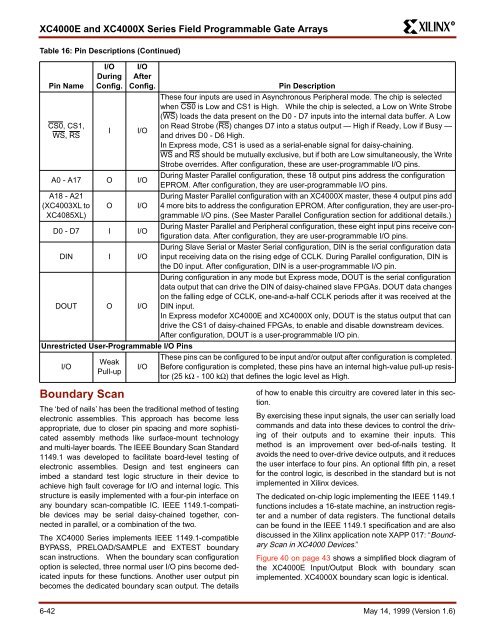
Table 16: Pin Descriptions (Continued)<br />
I/O I/O<br />
During After<br />
Pin Name Config. Config.<br />
Pin Description<br />
These four inputs are used in Asynchronous Peripheral mode. The chip is selected<br />
when CS0 is Low <strong>and</strong> CS1 is High. While the chip is selected, a Low on Write Strobe<br />
(WS) loads the <strong>data</strong> present on the D0 - D7 inputs into the internal <strong>data</strong> buffer. A Low<br />
CS0, CS1,<br />
on Read Strobe (RS) changes D7 into a status output — High if Ready, Low if Busy —<br />
I I/O<br />
WS, RS<br />
<strong>and</strong> drives D0 - D6 High.<br />
In Express mode, CS1 is used as a serial-enable signal for daisy-chaining.<br />
WS <strong>and</strong> RS should be mutually exclusive, but if both are Low simultaneously, the Write<br />
Strobe overrides. After configuration, these are user-programmable I/O pins.<br />
A0 - A17 O I/O<br />
During Master Parallel configuration, these 18 output pins address the configuration<br />
EPROM. After configuration, they are user-programmable I/O pins.<br />
A18 - A21<br />
(XC4003XL to<br />
XC4085XL)<br />
O I/O<br />
During Master Parallel configuration with an <strong>XC4000X</strong> master, these 4 output pins add<br />
4 more bits to address the configuration EPROM. After configuration, they are user-programmable<br />
I/O pins. (See Master Parallel Configuration section for additional details.)<br />
D0 - D7 I I/O<br />
During Master Parallel <strong>and</strong> Peripheral configuration, these eight input pins receive configuration<br />
<strong>data</strong>. After configuration, they are user-programmable I/O pins.<br />
DIN I I/O<br />
During Slave Serial or Master Serial configuration, DIN is the serial configuration <strong>data</strong><br />
input receiving <strong>data</strong> on the rising edge of CCLK. During Parallel configuration, DIN is<br />
the D0 input. After configuration, DIN is a user-programmable I/O pin.<br />
DOUT O I/O<br />
During configuration in any mode but Express mode, DOUT is the serial configuration<br />
<strong>data</strong> output that can drive the DIN of daisy-chained slave <strong>FPGA</strong>s. DOUT <strong>data</strong> changes<br />
on the falling edge of CCLK, one-<strong>and</strong>-a-half CCLK periods after it was received at the<br />
DIN input.<br />
In Express modefor <strong>XC4000E</strong> <strong>and</strong> <strong>XC4000X</strong> only, DOUT is the status output that can<br />
drive the CS1 of daisy-chained <strong>FPGA</strong>s, to enable <strong>and</strong> disable downstream devices.<br />
After configuration, DOUT is a user-programmable I/O pin.<br />
Unrestricted User-Programmable I/O Pins<br />
I/O<br />
Weak<br />
Pull-up<br />
Boundary Scan<br />
I/O<br />
The ‘bed of nails’ has been the traditional method of testing<br />
electronic assemblies. This approach has become less<br />
appropriate, due to closer pin spacing <strong>and</strong> more sophisticated<br />
assembly methods like surface-mount technology<br />
<strong>and</strong> multi-layer boards. The IEEE Boundary Scan St<strong>and</strong>ard<br />
1149.1 was developed to facilitate board-level testing of<br />
electronic assemblies. Design <strong>and</strong> test engineers can<br />
imbed a st<strong>and</strong>ard test logic structure in their device to<br />
achieve high fault coverage for I/O <strong>and</strong> internal logic. This<br />
structure is easily implemented with a four-pin interface on<br />
any boundary scan-compatible IC. IEEE 1149.1-compatible<br />
devices may be serial daisy-chained together, connected<br />
in parallel, or a combination of the two.<br />
The XC4000 <strong>Series</strong> implements IEEE 1149.1-compatible<br />
BYPASS, PRELOAD/SAMPLE <strong>and</strong> EXTEST boundary<br />
scan instructions. When the boundary scan configuration<br />
option is selected, three normal user I/O pins become dedicated<br />
inputs for these functions. Another user output pin<br />
becomes the dedicated boundary scan output. The details<br />
These pins can be configured to be input <strong>and</strong>/or output after configuration is completed.<br />
Before configuration is completed, these pins have an internal high-value pull-up resistor<br />
(25 kΩ - 100 kΩ) that defines the logic level as High.<br />
of how to enable this circuitry are covered later in this section.<br />
By exercising these input signals, the user can serially load<br />
comm<strong>and</strong>s <strong>and</strong> <strong>data</strong> into these devices to control the driving<br />
of their outputs <strong>and</strong> to examine their inputs. This<br />
method is an improvement over bed-of-nails testing. It<br />
avoids the need to over-drive device outputs, <strong>and</strong> it reduces<br />
the user interface to four pins. An optional fifth pin, a reset<br />
for the control logic, is described in the st<strong>and</strong>ard but is not<br />
implemented in <strong>Xilinx</strong> devices.<br />
The dedicated on-chip logic implementing the IEEE 1149.1<br />
functions includes a 16-state machine, an instruction register<br />
<strong>and</strong> a number of <strong>data</strong> registers. The <strong>functional</strong> details<br />
can be found in the IEEE 1149.1 specification <strong>and</strong> are also<br />
discussed in the <strong>Xilinx</strong> application note XAPP 017: “Boundary<br />
Scan in XC4000 Devices.”<br />
Figure 40 on page 43 shows a simplified block diagram of<br />
the <strong>XC4000E</strong> Input/Output Block with boundary scan<br />
implemented. <strong>XC4000X</strong> boundary scan logic is identical.<br />
6-42 May 14, 1999 (Version 1.6)