Innovative Treatment of Ceramics Using Low O2 ... - Sacmi
Innovative Treatment of Ceramics Using Low O2 ... - Sacmi
Innovative Treatment of Ceramics Using Low O2 ... - Sacmi

You also want an ePaper? Increase the reach of your titles
YUMPU automatically turns print PDFs into web optimized ePapers that Google loves.
High-Performance <strong>Ceramics</strong><br />
the same formulae as those used for determining<br />
the LEL and UEL by varying the oxygen percentages<br />
and it constitutes the interface between the<br />
line <strong>of</strong> stoichiometric combustion and the one<br />
for the least possible oxygen percentage for a reaction.<br />
In Fig. 5 the explosive range is marked by area 1.<br />
As the transition from non-explosive to explosive<br />
can occur very quickly, the limit-air-concentration<br />
(LAC) line is added for limiting a transition<br />
area which is connected with the LOC<br />
(limiting-oxygen-concentration) by the relation<br />
LOC = 0.209* LAC<br />
Every mixture to the right <strong>of</strong> the LOC is not ignitable<br />
and also relatively explosion-resistant. As<br />
with high methanal contents, however, a low<br />
oxygen infiltration can already provoke an explosion;<br />
this range is restricted even further by<br />
the ICR (inert gas-combustion gas rate) line.<br />
This straight line starts at an air concentration <strong>of</strong><br />
100 % and runs through the end point <strong>of</strong> the<br />
explosive range. The range determined by this<br />
method and limited by the LAC and ICR lines<br />
can now be classified as inert and consequently<br />
as safe. All other ranges must be considered explosive<br />
and thus to be avoided.<br />
The individual debinding components as well as<br />
their possible concentrations during the entire<br />
debinding process must be determined in preliminary<br />
tests as described above. Subsequently<br />
an explosion diagram as per Fig. 5 is created for<br />
each component if the measured concentrations<br />
are above the ICR line. As the measured concentrations<br />
<strong>of</strong> the previous processes have always<br />
been in the low ppm range, i.e. far below the ICR<br />
line, there is no explosion danger. A reliable oxygen<br />
measurement is sufficient for the supervision.<br />
6 Intermittent kiln plants with the new<br />
low O 2<br />
technology<br />
To meet the market and product requirements,<br />
kiln plants with this innovative technology must<br />
have the following features:<br />
• Intermittent and continuous production methods<br />
suitable for the required capacities<br />
• Debinding and sintering in one firing process<br />
and/or in one plant<br />
• No gas-tight plants but plants meeting the<br />
standard and the principles <strong>of</strong> shuttle kilns<br />
and/or tunnel kilns, to be able to resort to<br />
proven systems and to minimise investment<br />
costs<br />
• Heating by fuel for reasons <strong>of</strong> process requirements<br />
and operating costs<br />
• Precise atmosphere control, particularly during<br />
debinding, with due consideration <strong>of</strong> the regulations<br />
for explosion protection<br />
• High and uniform heat transfer with a binder<br />
degasification ensuring gentle product treatment<br />
• Use <strong>of</strong> thermal postcombustion for the binders<br />
to reduce energy consumption and thus avoid<br />
ecological damage<br />
• Safe operation in the non explosive range.<br />
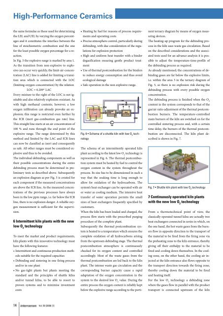
Fig. 6 • Schema <strong>of</strong> a shuttle kiln with low O 2<br />
technology<br />
The schema <strong>of</strong> an intermittently operated kiln<br />
plant according to the latest low O 2<br />
technology is<br />
represented in Fig. 6. The thermal postcombustion<br />
system must be heated by fuel to control the<br />
oxygen content in the system throughout the<br />
process. Its size has to be dimensioned in such a<br />
way that the soaking time is long enough to<br />
allow for oxidation <strong>of</strong> the hydrocarbons. The<br />
system’s heat exchanger can be operated with air<br />
or water as cooling medium. The intensive heat<br />
transfer <strong>of</strong> water operation permits the small<br />
sizes <strong>of</strong> heat exchangers frequently specified by<br />
customers.<br />
When the kiln has been loaded and charged, the<br />
process flow starts with the prescribed purging<br />
procedure <strong>of</strong> the complete plant.<br />
Subsequently the thermal postcombustion system<br />
is heated to a temperature which ensures the<br />
complete oxidation <strong>of</strong> all hydrocarbons arising<br />
from the upstream debinding stage. The thermal<br />
post combustion atmosphere is continuously<br />
checked for its oxygen content and controlled<br />
accordingly. Most <strong>of</strong> the waste gases from the<br />
thermal postcombustion are led back to the kiln<br />
plant. The intense waste gas circulation and the<br />
corresponding burner capacity cause a rapid<br />
adaptation <strong>of</strong> the oxygen concentration in the<br />
system to the desired low O 2<br />
value. During the<br />
entire process the oxygen content is reliably kept<br />
below the explosive range according to the perti-<br />
nent ternary diagram by means <strong>of</strong> oxygen measuring<br />
devices.<br />
The heating-up program for the debinding process<br />
in the kiln uses waste gas circulation. Based<br />
on the described con siderations and the associated<br />
tests used for an advance analysis it is possible<br />
to adjust the temperature-time-pr<strong>of</strong>ile <strong>of</strong><br />
the debinding process as required.<br />
As already mentioned, the concentrations <strong>of</strong> debinding<br />
gases are far below the explosive limits,<br />
i.e. within the area 3 in the ternary diagram <strong>of</strong><br />
Fig. 5, so there is no explosion risk during the<br />
debinding process with every possible oxygen<br />
concentration.<br />
The debinding process is finished when the O 2<br />
content in the system corresponds to that <strong>of</strong> the<br />
gas/air ratio adjustment <strong>of</strong> the thermal postcombustion<br />
burners. The temperature-controlled<br />
main burners <strong>of</strong> the kiln are switched on for the<br />
controlled sintering process and, with a certain<br />
time delay, the burners <strong>of</strong> the thermal postcombustion<br />
are disconnected. The kiln plant described<br />
is shown in Fig. 7.<br />
Fig. 7 • Shuttle kiln plant with low O 2<br />
technology<br />
7 Continuously operated kiln plants<br />
with the new low O 2<br />
technology<br />
From a thermotechnical point <strong>of</strong> view, the<br />
classic ally operated tunnel kilns are actually two<br />
heat exchangers connected in series in which, on<br />
the one hand, the hot waste gases from the burners<br />
flow in opposite direction to the transport <strong>of</strong><br />
the material to be fired from the firing zone via<br />
the preheating zone to the kiln entrance, thereby<br />
giving <strong>of</strong>f their enthalpy to the material to be<br />
fired and cooling down themselves. In the cooling<br />
zone, on the other hand, the cooling air injected<br />
at the kiln entrance also flows opposite to<br />
the transport direction towards the firing zone,<br />
thereby cooling down the material to be fired<br />
and heating itself.<br />
For the low O 2<br />
technology a debinding zone<br />
where the gases flow in parallel with the product<br />
transport is connected upstream <strong>of</strong> the kiln<br />
14 Vol. 58 (2009) [1]