Innovative Treatment of Ceramics Using Low O2 ... - Sacmi
Innovative Treatment of Ceramics Using Low O2 ... - Sacmi
Innovative Treatment of Ceramics Using Low O2 ... - Sacmi

You also want an ePaper? Increase the reach of your titles
YUMPU automatically turns print PDFs into web optimized ePapers that Google loves.
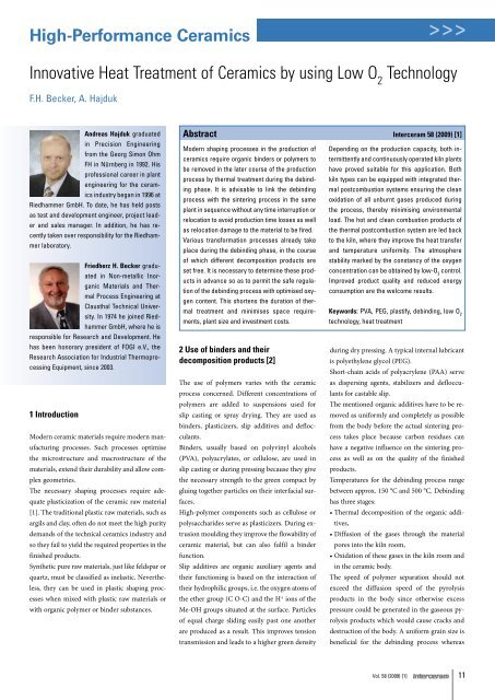
High-Performance <strong>Ceramics</strong> >>><br />
<strong>Innovative</strong> Heat <strong>Treatment</strong> <strong>of</strong> <strong>Ceramics</strong> by using <strong>Low</strong> O 2<br />
Technology<br />
F.H. Becker, A. Hajduk<br />
Andreas Hajduk graduated<br />
in Precision Engineering<br />
from the Georg Simon Ohm<br />
FH in Nürnberg in 1992. His<br />
pr<strong>of</strong>essional career in plant<br />
engineering for the ceramics<br />
industry began in 1996 at<br />
Riedhammer GmbH. To date, he has held posts<br />
as test and development engineer, project leader<br />
and sales manager. In addition, he has recently<br />
taken over responsibility for the Riedhammer<br />
laboratory.<br />
Friedherz H. Becker graduated<br />
in Non-metallic Inorganic<br />
Materials and Thermal<br />
Process Engineering at<br />
Clausthal Technical University.<br />
In 1974 he joined Riedhammer<br />
GmbH, where he is<br />
responsible for Research and Development. He<br />
has been honorary president <strong>of</strong> FOGI e.V., the<br />
Research Association for Industrial Thermoprocessing<br />
Equipment, since 2003.<br />
1 Introduction<br />
Modern ceramic materials require modern manufacturing<br />
processes. Such processes optimise<br />
the microstructure and macrostructure <strong>of</strong> the<br />
materials, extend their durability and allow complex<br />
geometries.<br />
The necessary shaping processes require adequate<br />
plasticization <strong>of</strong> the ceramic raw material<br />
[1]. The traditional plastic raw materials, such as<br />
argils and clay, <strong>of</strong>ten do not meet the high purity<br />
demands <strong>of</strong> the technical ceramics industry and<br />
so they fail to yield the required properties in the<br />
finished products.<br />
Synthetic pure raw materials, just like feldspar or<br />
quartz, must be classified as inelastic. Nevertheless,<br />
they can be used in plastic shaping processes<br />
when mixed with plastic raw materials or<br />
with organic polymer or binder substances.<br />
Abstract Interceram 58 (2009) [1]<br />
Modern shaping processes in the production <strong>of</strong><br />
ceramics require organic binders or polymers to<br />
be removed in the later course <strong>of</strong> the production<br />
process by thermal treatment during the debinding<br />
phase. It is advisable to link the debinding<br />
process with the sintering process in the same<br />
plant in sequence without any time interruption or<br />
relocation to avoid production time losses as well<br />
as relocation damage to the material to be fired.<br />
Various transformation processes already take<br />
place during the debinding phase, in the course<br />
<strong>of</strong> which different decomposition products are<br />
set free. It is necessary to determine these products<br />
in advance so as to permit the safe regulation<br />
<strong>of</strong> the debinding process with optimised oxygen<br />
content. This shortens the duration <strong>of</strong> thermal<br />
treatment and minimises space requirements,<br />
plant size and investment costs.<br />
2 Use <strong>of</strong> binders and their<br />
decomposition products [2]<br />
The use <strong>of</strong> polymers varies with the ceramic<br />
process concerned. Different concentrations <strong>of</strong><br />
polymers are added to suspensions used for<br />
slip casting or spray drying. They are used as<br />
binders, plasticizers, slip additives and deflocculants.<br />
Binders, usually based on polyvinyl alcohols<br />
(PVA), polyacrylates, or cellulose, are used in<br />
slip casting or during pressing because they give<br />
the necessary strength to the green compact by<br />
gluing together particles on their interfacial surfaces.<br />
High-polymer components such as cellulose or<br />
polysaccharides serve as plasticizers. During extrusion<br />
moulding they improve the flowability <strong>of</strong><br />
ceramic material, but can also fulfil a binder<br />
function.<br />
Slip additives are organic auxiliary agents and<br />
their functioning is based on the interaction <strong>of</strong><br />
their hydrophilic groups, i.e. the oxygen atoms <strong>of</strong><br />
the ether group (C O‐C) and the H + ions <strong>of</strong> the<br />
Me-OH groups situated at the surface. Particles<br />
<strong>of</strong> equal charge sliding easily past one another<br />
are produced as a result. This improves tension<br />
transmission and leads to a higher green density<br />
Depending on the production capacity, both intermittently<br />
and continuously operated kiln plants<br />
have proved suitable for this application. Both<br />
kiln types can be equipped with integrated thermal<br />
postcombustion systems ensuring the clean<br />
oxidation <strong>of</strong> all unburnt gases produced during<br />
the process, thereby minimising environmental<br />
load. The hot and clean combustion products <strong>of</strong><br />
the thermal postcombustion system are led back<br />
to the kiln, where they improve the heat transfer<br />
and temperature uniformity. The atmosphere<br />
stability marked by the constancy <strong>of</strong> the oxygen<br />
concentration can be obtained by low-O 2<br />
control.<br />
Improved product quality and reduced energy<br />
consumption are the welcome results.<br />
Keywords: PVA, PEG, plastify, debinding, low O 2<br />
technology, heat treatment<br />
during dry pressing. A typical internal lubricant<br />
is polyethylene glycol (PEG).<br />
Short-chain acids <strong>of</strong> polyacrylene (PAA) serve<br />
as dispersing agents, stabilizers and deflocculants<br />
for castable slip.<br />
The mentioned organic additives have to be removed<br />
as uniformly and completely as possible<br />
from the body before the actual sintering process<br />
takes place because carbon residues can<br />
have a negative influence on the sintering process<br />
as well as on the quality <strong>of</strong> the finished<br />
products.<br />
Temperatures for the debinding process range<br />
between approx. 150 °C and 500 °C. Debinding<br />
has three stages:<br />
• Thermal decomposition <strong>of</strong> the organic additives,<br />
• Diffusion <strong>of</strong> the gases through the material<br />
pores into the kiln room,<br />
• Oxidation <strong>of</strong> these gases in the kiln room and<br />
in the ceramic body.<br />
The speed <strong>of</strong> polymer separation should not<br />
exceed the diffusion speed <strong>of</strong> the pyrolysis<br />
products in the body since otherwise excess<br />
pressure could be generated in the gaseous pyrolysis<br />
products which would cause cracks and<br />
destruction <strong>of</strong> the body. A uniform grain size is<br />
beneficial for the debinding process whereas<br />
Vol. 58 (2009) [1] 11
High-Performance <strong>Ceramics</strong><br />
Fig. 1 • Differential thermal analysis<br />
Fig. 2 • Combustion diagram for Russian natural gas<br />
agglomerates or high-density areas have a retarding<br />
effect. The use <strong>of</strong> fine powder accelerates<br />
the sintering process, but it also reduces the debinding<br />
speed.<br />
In the production process the entire thermal<br />
treatment can last up to 80 h, with the debinding<br />
process taking place within a time frame <strong>of</strong> up to<br />
40 h. Long firing times push up energy and space<br />
requirements, factors which call for high investment<br />
and operating costs and should therefore<br />
be reduced to a minimum.<br />
3 Analysis <strong>of</strong> the debinding processes<br />
Table 1 gives an overview <strong>of</strong> the temperature<br />
range in which the decomposition reactions take<br />
place. However, it has to be considered that various<br />
ceramic materials have different catalytic<br />
effects on the temperature pr<strong>of</strong>ile <strong>of</strong> the decomposition<br />
reactions <strong>of</strong> polymers, e.g. Al 2<br />
O 3<br />
intensifies<br />
the decomposition process <strong>of</strong> the polymer<br />
chains and so the reactions proceed at lower<br />
temperatures [3]. During the debinding process<br />
the organic additives PVA, PEG and PAA decompose<br />
into a wide variety <strong>of</strong> chemical compounds,<br />
as shown in the Tables 2–4 [4].<br />
The thermal reactions proceeding in an industrial<br />
application test can be followed very clearly<br />
from the diagrams <strong>of</strong> the differential thermal<br />
analysis (DTA) (Fig. 1). While the organic decomposition<br />
products are escaping from the<br />
material to be fired, very distinct exothermic and<br />
endothermic reactions take place in some cases.<br />
Mostly the critical temperature range varies<br />
from 150–400 °C. An examination <strong>of</strong> the effect<br />
<strong>of</strong> the oxygen content on the intensity <strong>of</strong> the reactions<br />
reveals that the reactions can be influenced<br />
by the kiln atmosphere, which means that,<br />
in theory, a tool has been found for product debinding<br />
at the maximum possible speed without<br />
demands state <strong>of</strong> the art atmosphere control in a<br />
kiln or in certain kiln areas. If the requested finished<br />
product properties are not influenced by<br />
specific firing atmosphere conditions, the combustion<br />
should always take place under stoichiometric<br />
conditions for reasons <strong>of</strong> energy, i.e.<br />
complete combustion <strong>of</strong> the fuel with the lowest<br />
oxygen content. Figure 2 shows the combustion<br />
diagram for Russian natural gas, from which it<br />
can be seen that e.g. a 5 % deviation in the oxygen<br />
content in the firing atmosphere from the<br />
stoichiometric combustion point causes an approx.<br />
32 % increase <strong>of</strong> the waste gas volume, so<br />
the energy consumption will also rise by this<br />
amount.<br />
Special firing atmosphere conditions are necessary<br />
e.g. in the fast firing process for glost-firing<br />
hard porcelain. In this case fast firing signifies<br />
that the complete firing process including coolrisking<br />
a decline in quality. In the present case it<br />
is advisable to accelerate the debinding process<br />
and make it energetically efficient by a low O 2<br />
adjustment.<br />
4 Kiln plants with low O 2<br />
technology<br />
Depending on the production capacity and other<br />
factors, continuously operated kiln plants are<br />
used for large production quantities, i.e. tunnel<br />
kilns in the form <strong>of</strong> roller kilns, pusher-type<br />
kilns with tray conveyance, tunnel kilns with car<br />
conveyance, and rotary kilns. For smaller production<br />
volumes intermittently operated kiln<br />
plants are suitable, such as shuttle kilns, top-hat<br />
kilns, elevator and chamber kilns.<br />
In the broadest sense the low O 2<br />
technology can<br />
be used for all the above-mentioned kiln plants.<br />
The basic principle <strong>of</strong> the low O 2<br />
technology<br />
Table 3 • Pyrolysis product <strong>of</strong> PEG<br />
C 10<br />
H 8<br />
Table 1 • Decomposition ranges <strong>of</strong><br />
Naphthalene Cresol<br />
C 7<br />
H 8<br />
O<br />
polymers<br />
Products <strong>of</strong> pyrolysis Molecular formula<br />
Organic substance Decomposition range/°C Formaldehyde<br />
CH 2<br />
O<br />
PVA 200–300<br />
Acetaldehyde<br />
CH 3<br />
CHO<br />
PEG 150–250<br />
Valeraldehyde<br />
C 5<br />
H 10<br />
O<br />
PAA 250–300<br />
Mono-,di- and trimers<br />
<strong>of</strong> ethylene glycol<br />
C 2<br />
H 4<br />
(OH) 2<br />
Table 2 • Pyrolysis products <strong>of</strong> PVA<br />
Methyl-1.3-dioxolane C 4<br />
H 6<br />
O 3<br />
Products <strong>of</strong> pyrolysis Molecular formula<br />
Benzene C 6<br />
H 6<br />
Formaldehyde<br />
CH 2<br />
O<br />
Acetaldehyde<br />
CH 3<br />
CHO<br />
Table 4 • Pyrolysis product <strong>of</strong> PAA<br />
Cotonaldehyde<br />
C 4<br />
H 6<br />
O<br />
Products <strong>of</strong> pyrolysis Molecular formula<br />
Benzene C 6<br />
H 6<br />
Formaldehyde<br />
CH 2<br />
O<br />
Phenol<br />
C 6<br />
H 5<br />
OH<br />
Acetaldehyde<br />
CH 3<br />
CHO<br />
Benzaldehyde<br />
C 7<br />
H 6<br />
O<br />
Propionaldehyde<br />
C 3<br />
H 6<br />
O<br />
Toluene C 7<br />
H 8<br />
2-butanone<br />
C 4<br />
H 8<br />
O<br />
Styrol C 8<br />
H 8<br />
Benzene C 6<br />
H 6<br />
Cresol<br />
C 7<br />
H 8<br />
O<br />
Xylene C 8<br />
H 10<br />
Benz<strong>of</strong>uran<br />
C 8<br />
H 6<br />
O<br />
Phenol<br />
C 6<br />
H 5<br />
OH<br />
12 Vol. 58 (2009) [1]
ing is realised within 4 to 8 hours. The desired<br />
colour and thus quality <strong>of</strong> the porcelain products<br />
is adjusted and supervised by ensuring a nearstoichiometric,<br />
but reducing firing atmosphere<br />
(air factor λ ≈ 0.95) in the temperature range <strong>of</strong><br />
approx. 1100 °C to 1400 °C. The quality <strong>of</strong> electrotechnical<br />
porcelain, such as high-voltage insulators,<br />
is influenced in like manner.<br />
The thermal treatment <strong>of</strong> bulk solids under certain<br />
oxygen-deficient conditions can also be<br />
carried out in indirectly heated rotary kilns<br />
equipped with special sealings (Fig. 3) and with<br />
an appropriate lance technology for purging<br />
their kiln room e.g. with inert gases.<br />
For larger production capacities <strong>of</strong> s<strong>of</strong>t ferrites,<br />
electrically heated, gas-tight roller kilns and particularly<br />
gas-tight pusher-type kilns with tray<br />
conveyance are the perfect choice.<br />
The magnetic properties <strong>of</strong> s<strong>of</strong>t ferrites are obtained<br />
by a very quick change from near atmosphere<br />
conditions to oxygen ranges <strong>of</strong> up to<br />
30 ppm. This change <strong>of</strong> atmosphere is necessary<br />
between soaking time at maximum temperature<br />
and below Curie temperature. Depending on the<br />
product, however, different oxygen contents<br />
must already be maintained in the heating-up<br />
phase.<br />
products. The burning <strong>of</strong> carbon can be prevented<br />
only if no oxygen and, according to the<br />
Boudouard equilibrium, no CO 2<br />
gas comes into<br />
contact with the carbon products during the<br />
baking process. The typical production plant is<br />
the ring pit furnace for baking anodes and cathodes.<br />
This quasi-continuous plant consists <strong>of</strong><br />
individual sections filled with products and intermediate<br />
channels <strong>of</strong> ceramic pit bricks. A<br />
Fig. 4 • Two electrically heated gas-tight top-hat<br />
kilns<br />
burner ramp “moves” at a periodic interval <strong>of</strong><br />
26–32 h from one section to the next one. Its<br />
burners produce waste gases which are led<br />
through the channels, thereby ensuring the<br />
indir ect heat transfer. Before each section is<br />
closed, the product is completely packed in coke<br />
to make sure that no oxygen can penetrate.<br />
the lower explosive limit (LEL) – up to the upper<br />
explosive limit (UEL) <strong>of</strong> 73 %. The following<br />
explosion prevention representation refers to the<br />
ternary system <strong>of</strong> methanal, nitrogen and air as<br />
an example (Fig. 5).<br />
The vertices <strong>of</strong> the three axes with a scale division<br />
<strong>of</strong> 0–100% each define the initial state <strong>of</strong> a<br />
pure component. In order to assign points in the<br />
ternary system clearly to the percentages, the<br />
reference axes are to be displaced until they meet<br />
the required concentration point. The three concentration<br />
values <strong>of</strong> the substances together<br />
must always add up to 100 %. To ascertain the<br />
concentration <strong>of</strong> one point, the graphic determination<br />
<strong>of</strong> the percentages <strong>of</strong> two components is<br />
sufficient, the third one can be calculated on this<br />
basis. The LEL indicates the minimum percentage<br />
<strong>of</strong> combustible gas in the substance mixture<br />
necessary for an explosion. Under the LEL, no<br />
explosion is possible as the existing concentration<br />
<strong>of</strong> the combustible substance is too low. The<br />
UEL indicates the maximum possible percentage<br />
<strong>of</strong> combustibles in the substance mixture for an<br />
5 The new low O 2<br />
technology<br />
Fig. 3 • Indirectly heated rotary kiln with atmosphere<br />
control<br />
Roller kilns and pusher-type kilns with tray conveyance<br />
are also used for manufacturing other<br />
electronic ceramics products and ceramic diesel<br />
particulate filters.<br />
For smaller production capacities <strong>of</strong> s<strong>of</strong>t ferrites<br />
intermittent kiln plants are sufficient. The production<br />
unit most frequently used for this purpose<br />
is the electrically heated gas-tight top-hat<br />
kiln (Fig. 4), which also achieves the low oxygen<br />
values mentioned above.<br />
Another example among the large number <strong>of</strong><br />
well-known applications <strong>of</strong> thermal treatment at<br />
low oxygen content is the production <strong>of</strong> carbon<br />
The new low O 2<br />
technology for innovative heat<br />
treatment plants with integrated debinding process<br />
differs from the described plants mainly in<br />
terms <strong>of</strong> process engineering.<br />
The new low O 2<br />
technology is a thermal process<br />
technology achieving the shortest, energetically<br />
most efficient thermal treatment <strong>of</strong> high-quality<br />
ceramic products under near-stoichiometric<br />
combustion. A closer examination <strong>of</strong> the debinding<br />
process shows that the most important control<br />
variable is the dependence <strong>of</strong> this process on<br />
the oxygen content and the reaction intensity.<br />
Even if the concentrations <strong>of</strong> the gaseous debinding<br />
products are in the non-hazardous ppm<br />
range in all cases known up to now, the debinding<br />
reactions must be determined for the new<br />
low O 2<br />
technology, and the possible concentrations<br />
during the debinding process must be calculated<br />
in order to prevent deflagrations.<br />
As shown in Tables 1, 2 and 3, the main substance<br />
released during the debinding process is<br />
formaldehyde, also called methanal. The gases<br />
are explosive in a gas-air mixture <strong>of</strong> from 7 % –<br />
Fig. 5 • Ternary system methanal-nitrogen-air<br />
1 = explosive mixture<br />
2 = inert mixture<br />
3 = safe mixture with variable oxygen concentrations<br />
ignition. Above the UEL an explosion is not possible<br />
either, as the existing concentration <strong>of</strong> an<br />
oxidant, mostly oxygen, is too low. Between the<br />
LEL and the UEL an explosion must be expected<br />
if an ignition source exists. The limits are drawn<br />
in Fig. 5.<br />
The LEL and the UEL can be calculated with<br />
corresponding formulae [5]. To fix an explosive<br />
range, another third point limiting the explosive<br />
range is required. This point is calculated with<br />
Vol. 58 (2009) [1] 13
High-Performance <strong>Ceramics</strong><br />
the same formulae as those used for determining<br />
the LEL and UEL by varying the oxygen percentages<br />
and it constitutes the interface between the<br />
line <strong>of</strong> stoichiometric combustion and the one<br />
for the least possible oxygen percentage for a reaction.<br />
In Fig. 5 the explosive range is marked by area 1.<br />
As the transition from non-explosive to explosive<br />
can occur very quickly, the limit-air-concentration<br />
(LAC) line is added for limiting a transition<br />
area which is connected with the LOC<br />
(limiting-oxygen-concentration) by the relation<br />
LOC = 0.209* LAC<br />
Every mixture to the right <strong>of</strong> the LOC is not ignitable<br />
and also relatively explosion-resistant. As<br />
with high methanal contents, however, a low<br />
oxygen infiltration can already provoke an explosion;<br />
this range is restricted even further by<br />
the ICR (inert gas-combustion gas rate) line.<br />
This straight line starts at an air concentration <strong>of</strong><br />
100 % and runs through the end point <strong>of</strong> the<br />
explosive range. The range determined by this<br />
method and limited by the LAC and ICR lines<br />
can now be classified as inert and consequently<br />
as safe. All other ranges must be considered explosive<br />
and thus to be avoided.<br />
The individual debinding components as well as<br />
their possible concentrations during the entire<br />
debinding process must be determined in preliminary<br />
tests as described above. Subsequently<br />
an explosion diagram as per Fig. 5 is created for<br />
each component if the measured concentrations<br />
are above the ICR line. As the measured concentrations<br />
<strong>of</strong> the previous processes have always<br />
been in the low ppm range, i.e. far below the ICR<br />
line, there is no explosion danger. A reliable oxygen<br />
measurement is sufficient for the supervision.<br />
6 Intermittent kiln plants with the new<br />
low O 2<br />
technology<br />
To meet the market and product requirements,<br />
kiln plants with this innovative technology must<br />
have the following features:<br />
• Intermittent and continuous production methods<br />
suitable for the required capacities<br />
• Debinding and sintering in one firing process<br />
and/or in one plant<br />
• No gas-tight plants but plants meeting the<br />
standard and the principles <strong>of</strong> shuttle kilns<br />
and/or tunnel kilns, to be able to resort to<br />
proven systems and to minimise investment<br />
costs<br />
• Heating by fuel for reasons <strong>of</strong> process requirements<br />
and operating costs<br />
• Precise atmosphere control, particularly during<br />
debinding, with due consideration <strong>of</strong> the regulations<br />
for explosion protection<br />
• High and uniform heat transfer with a binder<br />
degasification ensuring gentle product treatment<br />
• Use <strong>of</strong> thermal postcombustion for the binders<br />
to reduce energy consumption and thus avoid<br />
ecological damage<br />
• Safe operation in the non explosive range.<br />
Fig. 6 • Schema <strong>of</strong> a shuttle kiln with low O 2<br />
technology<br />
The schema <strong>of</strong> an intermittently operated kiln<br />
plant according to the latest low O 2<br />
technology is<br />
represented in Fig. 6. The thermal postcombustion<br />
system must be heated by fuel to control the<br />
oxygen content in the system throughout the<br />
process. Its size has to be dimensioned in such a<br />
way that the soaking time is long enough to<br />
allow for oxidation <strong>of</strong> the hydrocarbons. The<br />
system’s heat exchanger can be operated with air<br />
or water as cooling medium. The intensive heat<br />
transfer <strong>of</strong> water operation permits the small<br />
sizes <strong>of</strong> heat exchangers frequently specified by<br />
customers.<br />
When the kiln has been loaded and charged, the<br />
process flow starts with the prescribed purging<br />
procedure <strong>of</strong> the complete plant.<br />
Subsequently the thermal postcombustion system<br />
is heated to a temperature which ensures the<br />
complete oxidation <strong>of</strong> all hydrocarbons arising<br />
from the upstream debinding stage. The thermal<br />
post combustion atmosphere is continuously<br />
checked for its oxygen content and controlled<br />
accordingly. Most <strong>of</strong> the waste gases from the<br />
thermal postcombustion are led back to the kiln<br />
plant. The intense waste gas circulation and the<br />
corresponding burner capacity cause a rapid<br />
adaptation <strong>of</strong> the oxygen concentration in the<br />
system to the desired low O 2<br />
value. During the<br />
entire process the oxygen content is reliably kept<br />
below the explosive range according to the perti-<br />
nent ternary diagram by means <strong>of</strong> oxygen measuring<br />
devices.<br />
The heating-up program for the debinding process<br />
in the kiln uses waste gas circulation. Based<br />
on the described con siderations and the associated<br />
tests used for an advance analysis it is possible<br />
to adjust the temperature-time-pr<strong>of</strong>ile <strong>of</strong><br />
the debinding process as required.<br />
As already mentioned, the concentrations <strong>of</strong> debinding<br />
gases are far below the explosive limits,<br />
i.e. within the area 3 in the ternary diagram <strong>of</strong><br />
Fig. 5, so there is no explosion risk during the<br />
debinding process with every possible oxygen<br />
concentration.<br />
The debinding process is finished when the O 2<br />
content in the system corresponds to that <strong>of</strong> the<br />
gas/air ratio adjustment <strong>of</strong> the thermal postcombustion<br />
burners. The temperature-controlled<br />
main burners <strong>of</strong> the kiln are switched on for the<br />
controlled sintering process and, with a certain<br />
time delay, the burners <strong>of</strong> the thermal postcombustion<br />
are disconnected. The kiln plant described<br />
is shown in Fig. 7.<br />
Fig. 7 • Shuttle kiln plant with low O 2<br />
technology<br />
7 Continuously operated kiln plants<br />
with the new low O 2<br />
technology<br />
From a thermotechnical point <strong>of</strong> view, the<br />
classic ally operated tunnel kilns are actually two<br />
heat exchangers connected in series in which, on<br />
the one hand, the hot waste gases from the burners<br />
flow in opposite direction to the transport <strong>of</strong><br />
the material to be fired from the firing zone via<br />
the preheating zone to the kiln entrance, thereby<br />
giving <strong>of</strong>f their enthalpy to the material to be<br />
fired and cooling down themselves. In the cooling<br />
zone, on the other hand, the cooling air injected<br />
at the kiln entrance also flows opposite to<br />
the transport direction towards the firing zone,<br />
thereby cooling down the material to be fired<br />
and heating itself.<br />
For the low O 2<br />
technology a debinding zone<br />
where the gases flow in parallel with the product<br />
transport is connected upstream <strong>of</strong> the kiln<br />
14 Vol. 58 (2009) [1]
Fig. 8 • Schema <strong>of</strong> a debinding zone for a tunnel<br />
kiln<br />
plant. Thus the gases loaded with hydrocarbons<br />
are led to increasing temperatures so that, with a<br />
correspondingly low oxygen concentration, most<br />
<strong>of</strong> them already burn up in this zone. The gases<br />
flow to the thermal postcombustion section via<br />
the chimney installed between the debinding<br />
and the preheating zone. In the thermal postcombustion<br />
system any residual hydrocarbons<br />
are burnt up completely by means <strong>of</strong> a controlled<br />
thermal treatment. Not even condensates can<br />
deposit in the waste gas piping due to the high<br />
temperature. The clean waste gases from the<br />
thermal postcombustion process are led back to<br />
the kiln and, supported by special burners, serve<br />
the direct heating <strong>of</strong> the debinding zone.<br />
These special burners acting as injectors for the<br />
gases from the thermal postcombustion are used<br />
to control the temperature in the debinding<br />
zones <strong>of</strong> the plant as well as the oxygen atmosphere<br />
in these zones. The oxygen measurement<br />
with the incorporated control guarantees constant<br />
low O 2<br />
atmo sphere conditions throughout<br />
the process. The system thus ensures safe operation<br />
outside the explosive limits. The large gas<br />
circulation volumes in the kiln channel create<br />
good uniform temperatures and constant atmospheric<br />
concentrations.<br />
The basic principle <strong>of</strong> the debinding system described<br />
and represented schematically in Fig. 8<br />
has meanwhile become established. It stands out<br />
for its low energy consumption, safe operating<br />
mode and low waste gas losses with a minimum<br />
environmental load limited to the CO 2<br />
particles<br />
which cannot be avoided during the combustion<br />
<strong>of</strong> fossil fuels.<br />
With tunnel kilns based on this principle, the<br />
duration <strong>of</strong> the total thermal treatment can be<br />
reduced by 50–70 % compared to conventional<br />
technology. Other excellent advantages consist<br />
in correspondingly smaller, space-saving plant<br />
sizes with lower investment costs.<br />
References<br />
[1] Locher, C., Pfaff, E., Schulz, P., Zografou, C.:<br />
Untersuchungen zum Ausbrennen organischer<br />
Substanzen im keramischen Scherben.<br />
Keram. Z. 34 (1982) [7] 361–364<br />
[2] Becker, F.: Debinding processes – physical<br />
and chemical conclusions and their practical<br />
realisations. cfi 83 (2006) [5] E2–E13<br />
[3] Ferrato, M., Cartier,T., Baumard, J.F., Coudamy,<br />
G.: Der Bindemittelabgang in keramischen<br />
Scherben. cfi/Ber. DKG 71 (1994)<br />
[1/2] 8–12<br />
[4] Ziegler, G., Willert-Porada, M.: Schadst<strong>of</strong>freduzierung<br />
durch Prozessoptimierung bei<br />
der thermischen Zersetzung organischer<br />
Additivsysteme für die keramische Formgebung<br />
unter Einbeziehung der Mikrowelleneinkopplung.<br />
Report to research project no.<br />
12068 N<br />
[5] Fuß, O.: Ermittlung und Berechnung der<br />
Sauerst<strong>of</strong>fgrenzreaktion von brennbaren<br />
Gasen. Dissertation des Fachbereichs Chemie,<br />
Universität Duisburg-Essen, Mai 2004<br />
Received: 10. 12. 2008<br />
New on the Market<br />
Partnership Between Siti-B&T<br />
Group and Nuova Fima<br />
Siti-B&T Group and Nuova Fima, two global<br />
leaders in the ceramics machinery sector, have<br />
signed a partnership which concerns a specific<br />
production process, the “end <strong>of</strong> line”.<br />
The strategic collaboration is born from the wish<br />
<strong>of</strong> both companies to supply the market with top<br />
technologic solutions on the whole range, making<br />
the most <strong>of</strong> the experience, the perfections<br />
and the extremely high product specialisations<br />
<strong>of</strong> both groups.<br />
The innovative sorting line Dynamic Synthesis is<br />
the first result <strong>of</strong> the new partnership, created<br />
from a tight collaboration which seen Siti-B&T<br />
Group and Nuova Fima work together, and also<br />
includes an engineering, assistance and after<br />
sales service. The commercial policy decided by<br />
the two companies will contribute to improving<br />
the product <strong>of</strong>fer.<br />
The new sorting line is in complete conformation<br />
with the current market demands, equipped with<br />
mono stacker with dynamic assignment system<br />
and it boasts a highly reliable packing system. It is<br />
equipped with Nuova Firma hardware and s<strong>of</strong>tware<br />
and tested electronic equipment.<br />
Dynamic Synthesis will be proposed by Siti-B&T<br />
Group for all new complete plants equipped with<br />
the adequate specifications (sizes from 15 cm ×<br />
15 cm to 60 cm × 60 cm), while Nuova Fima will<br />
propose the machine directly to its ceramic clients.<br />
New MICROMATIC System<br />
for Cerámica Rioboo<br />
The Cerámica Rioboo brickworks <strong>of</strong> Pravio (A<br />
Coruña) is the last – but not least – brickyard<br />
opting for solid fuels in Spain.<br />
This Galician producer <strong>of</strong> hollow bricks will<br />
count in the next weeks with a solid fuel firing<br />
system model MICROMATIC that will use petroleum<br />
coke as the main fuel in the kiln, for an<br />
output <strong>of</strong> approx. 250 tm/d. The fuel used in the<br />
preheating zone will be natural gas.<br />
Beralmar has already supplied more than 200<br />
solid fuel (petcoke, coals, etc.) firing systems<br />
over the last quarter <strong>of</strong> century, the half <strong>of</strong> which<br />
have been installed in the last 8 years alone.<br />
Such boom in the use <strong>of</strong> solid fuels is not just<br />
explained by the price increases <strong>of</strong> gas and heavy<br />
oil, but also by the existance <strong>of</strong> adequate technologies<br />
for their consumption, which are constantly<br />
updated.<br />
Vol. 58 (2009) [1] 15