Formula SAE A Guide to Meeting the Structure Equivalency ...
Formula SAE A Guide to Meeting the Structure Equivalency ...
Formula SAE A Guide to Meeting the Structure Equivalency ...

Create successful ePaper yourself
Turn your PDF publications into a flip-book with our unique Google optimized e-Paper software.
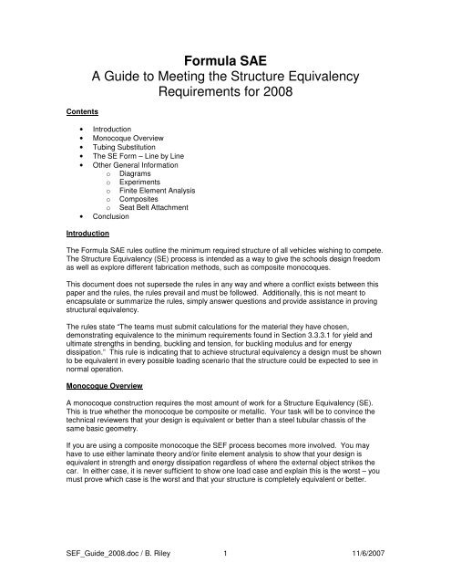
Contents<br />
<strong>Formula</strong> <strong>SAE</strong><br />
A <strong>Guide</strong> <strong>to</strong> <strong>Meeting</strong> <strong>the</strong> <strong>Structure</strong> <strong>Equivalency</strong><br />
Requirements for 2008<br />
• Introduction<br />
• Monocoque Overview<br />
• Tubing Substitution<br />
• The SE Form – Line by Line<br />
• O<strong>the</strong>r General Information<br />
o Diagrams<br />
o Experiments<br />
o Finite Element Analysis<br />
o Composites<br />
o Seat Belt Attachment<br />
• Conclusion<br />
Introduction<br />
The <strong>Formula</strong> <strong>SAE</strong> rules outline <strong>the</strong> minimum required structure of all vehicles wishing <strong>to</strong> compete.<br />
The <strong>Structure</strong> <strong>Equivalency</strong> (SE) process is intended as a way <strong>to</strong> give <strong>the</strong> schools design freedom<br />
as well as explore different fabrication methods, such as composite monocoques.<br />
This document does not supersede <strong>the</strong> rules in any way and where a conflict exists between this<br />
paper and <strong>the</strong> rules, <strong>the</strong> rules prevail and must be followed. Additionally, this is not meant <strong>to</strong><br />
encapsulate or summarize <strong>the</strong> rules, simply answer questions and provide assistance in proving<br />
structural equivalency.<br />
The rules state “The teams must submit calculations for <strong>the</strong> material <strong>the</strong>y have chosen,<br />
demonstrating equivalence <strong>to</strong> <strong>the</strong> minimum requirements found in Section 3.3.3.1 for yield and<br />
ultimate strengths in bending, buckling and tension, for buckling modulus and for energy<br />
dissipation.” This rule is indicating that <strong>to</strong> achieve structural equivalency a design must be shown<br />
<strong>to</strong> be equivalent in every possible loading scenario that <strong>the</strong> structure could be expected <strong>to</strong> see in<br />
normal operation.<br />
Monocoque Overview<br />
A monocoque construction requires <strong>the</strong> most amount of work for a <strong>Structure</strong> <strong>Equivalency</strong> (SE).<br />
This is true whe<strong>the</strong>r <strong>the</strong> monocoque be composite or metallic. Your task will be <strong>to</strong> convince <strong>the</strong><br />
technical reviewers that your design is equivalent or better than a steel tubular chassis of <strong>the</strong><br />
same basic geometry.<br />
If you are using a composite monocoque <strong>the</strong> SEF process becomes more involved. You may<br />
have <strong>to</strong> use ei<strong>the</strong>r laminate <strong>the</strong>ory and/or finite element analysis <strong>to</strong> show that your design is<br />
equivalent in strength and energy dissipation regardless of where <strong>the</strong> external object strikes <strong>the</strong><br />
car. In ei<strong>the</strong>r case, it is never sufficient <strong>to</strong> show one load case and explain this is <strong>the</strong> worst – you<br />
must prove which case is <strong>the</strong> worst and that your structure is completely equivalent or better.<br />
SEF_<strong>Guide</strong>_2008.doc / B. Riley 1 11/6/2007
Tubing Substitution<br />
Many of <strong>the</strong> SE submissions received concern substituting different sized tubing for roll hoops,<br />
bracing and side impact tubes. For example, consider <strong>the</strong> side impact tubes. In a side impact<br />
<strong>the</strong> side impact tubes isolate <strong>the</strong> driver from <strong>the</strong> impacting object, and dissipate <strong>the</strong> energy of <strong>the</strong><br />
collision. This means that a side impact structure must be shown <strong>to</strong> have <strong>the</strong> same strength as<br />
<strong>the</strong> three steel tube design outlined in <strong>the</strong> rules, as well as energy absorption. If you are simply<br />
replacing <strong>the</strong> tubes with larger diameter and stronger alloy steels, it becomes quite easy <strong>to</strong> show<br />
that in all scenarios <strong>the</strong> new design is superior. Calculating <strong>the</strong> cross sectional areas and<br />
moments of inertia and comparing <strong>the</strong>m back <strong>to</strong> <strong>the</strong> baseline tubes effectively accomplishes this,<br />
with supporting explanation of your thought process.<br />
The SE Form – Line by Line<br />
The following excerpt is taken from <strong>the</strong> SE form and shows how <strong>the</strong> major structures of <strong>the</strong> car<br />
are broken down. Please always include a fully filled out SE form with your submission. There is<br />
also an additional column for you <strong>to</strong> summarize your design such as “1.00”x0.049” square tube<br />
with ¼” hole.” This will assist <strong>the</strong> scrutineers at Technical Inspection.<br />
3.3.4.2 Main Roll Hoop<br />
3.3.4.2 Main Roll Hoop Attachment <strong>to</strong> Monocoque<br />
3.3.4.3 Front Roll Hoop<br />
3.3.5.1 Main Roll Hoop Bracing<br />
3.3.5.2 Front Roll Hoop Bracing<br />
3.3.5.3 Monocoque Bracing Attachment<br />
3.3.6.1 Front Bulkhead<br />
3.3.6.1 Monocoque Front Bulkhead<br />
3.3.6.2 Front Bulkhead Support<br />
3.3.6.2 Monocoque Front Bulkhead Support<br />
3.3.6.3 Impact Attenua<strong>to</strong>r Attachment<br />
3.3.8.1 Tube Frames Side Impact <strong>Structure</strong><br />
3.3.8.2 Composite Monocoque Side Impact Protection<br />
3.3.8.3 Metal Monocoque Side Impact Protection<br />
3.4.1 Monocoque Safety Harness Attachment<br />
We will now examine each item in more detail.<br />
3.3.4.2 Main Roll Hoop<br />
Because main roll hoops must be steel, most equivalencies will concern <strong>the</strong> diameter and wall<br />
thickness. Make sure your design does not fall below <strong>the</strong> minimum wall thickness given in <strong>the</strong><br />
rules (3.3.3.2.2 Steel Tubing Requirements), and has sufficient area, modulus and material<br />
properties. Remember, your main roll hoop and front roll hoop must have an exposed portion<br />
with inspection holes for determining diameter and wall thickness.<br />
SEF_<strong>Guide</strong>_2008.doc / B. Riley 2 11/6/2007
3.3.4.2 Main Roll Hoop Attachment <strong>to</strong> Monocoque<br />
Proving equivalency of <strong>the</strong> main roll hoop attachment can be trickier than showing equivalency of<br />
<strong>the</strong> roll hoop itself. Rule 3.3.4.2 states that <strong>the</strong> main roll hoop must be attached with an adequate<br />
number of 8mm bolts and 2mm thick (backing) plates. Use of adhesive as additional structural<br />
transfer is acceptable, but we want <strong>to</strong> ensure that <strong>the</strong> main roll hoop is structurally attached with<br />
mechanical fasteners that we can verify at Technical Inspection. The quantity, location and<br />
design details of <strong>the</strong> main hoop attachment, including drawings, must be provided with supporting<br />
calculations.<br />
3.3.4.3 Front Roll Hoop<br />
Composites are not allowed for Front Roll Hoops. They must be closed section metal tubing, and<br />
must be connected securely <strong>to</strong> your monocoque. Closed section includes round, near round, box<br />
and o<strong>the</strong>r tubing shapes that form a closed cross section. Make sure your design does not fall<br />
below <strong>the</strong> minimum wall thickness given in <strong>the</strong> rules (3.3.3.2 Alternative Tubing and Material),<br />
and has sufficient area, modulus and material properties.<br />
Unlike <strong>the</strong> Main Hoop, Rule 3.3.4.2 does not govern <strong>the</strong> front roll hoop attachment. Use of<br />
adhesives is acceptable, if <strong>the</strong> hoop is completely contained in composite and <strong>the</strong> ply material<br />
and adhesives are demonstrated <strong>to</strong> have sufficient strength. The design details of <strong>the</strong> main hoop<br />
attachment, including drawings, must be provided with supporting calculations.<br />
Remember, your main roll hoop and front roll hoop must have an exposed portion with inspection<br />
holes for determining diameter and wall thickness.<br />
3.3.5.1 Main Roll Hoop Bracing<br />
The rules dictate a steel closed-section main roll hoop bracing. Additionally, provide detailed<br />
information on <strong>the</strong> manner of <strong>the</strong> bracing attachment. If <strong>the</strong> bracing is welded in<strong>to</strong> <strong>the</strong> structure at<br />
both ends it is not considered mechanically attached. The bracing is considered mechanically<br />
attached if fasteners are used at one or both ends, regardless if <strong>the</strong> team has any intention of<br />
disconnecting <strong>the</strong> attachment while at <strong>the</strong> competition. Section 3.3.5.5 (Mechanically Attached<br />
Roll Hoop Bracing) should be referenced which outlines acceptable methods of fastening <strong>to</strong> a<br />
space frame.<br />
New in 2008 is <strong>the</strong> following phrase near <strong>the</strong> end of 3.3.5.1:<br />
“Bracing loads must not be fed solely in<strong>to</strong> <strong>the</strong> engine, transmission or differential, i.e. <strong>the</strong><br />
bracing must terminate at a node where <strong>the</strong>re is a load path through <strong>the</strong> Primary<br />
<strong>Structure</strong>.”<br />
The basic test that will be applied for 2008 and beyond for <strong>the</strong> Main Hoop Bracing is that with <strong>the</strong><br />
engine and transmission removed, <strong>the</strong>re must be a load path, made from approved sized steel<br />
tubing, from <strong>the</strong> bot<strong>to</strong>m of <strong>the</strong> Main Hoop Bracing back <strong>to</strong> <strong>the</strong> Main Hoop. The minimum<br />
dimensions of approved steel tubing are 1.00” OD x 0.049” wall. Preferably it would be 1.00” OD<br />
x 0.065” wall.<br />
If you want <strong>to</strong> use part of a Powertrain component (such as a homemade differential casing)<br />
anywhere in <strong>the</strong> load path you will need <strong>to</strong> show equivalency with that component and all<br />
interconnecting components back <strong>to</strong> <strong>the</strong> main roll hoop. You have <strong>to</strong> show equivalency against<br />
<strong>the</strong> 1.00” OD x 0.049” steel tube that is required.<br />
If attaching <strong>to</strong> a monocoque, please see section 3.3.5.3 as all Main Hoop <strong>to</strong> monocoque<br />
attachments are by definition Mechanically Attached.<br />
SEF_<strong>Guide</strong>_2008.doc / B. Riley 3 11/6/2007
3.3.5.2 Front Roll Hoop Bracing<br />
Front roll hoop bracing can be metallic tubing. The composite monocoque may also serve as <strong>the</strong><br />
front roll hoop bracing. Provide standard composite information. The bracing must form a<br />
continuous load path from <strong>the</strong> roll hoop <strong>to</strong> <strong>the</strong> major structure of <strong>the</strong> chassis. The rules say <strong>the</strong><br />
bracing should extend <strong>to</strong> structure in front of <strong>the</strong> drivers feet, which does not mean it is<br />
manda<strong>to</strong>ry.<br />
3.3.5.3 Monocoque Bracing Attachment<br />
When <strong>the</strong> bracing attaches <strong>to</strong> a monocoque, <strong>the</strong>re are additional design cases <strong>to</strong> consider. First,<br />
<strong>the</strong> mounting plates and backup plates should be sized <strong>to</strong> prevent all <strong>the</strong> possible failure modes<br />
at <strong>the</strong> interface, such as perimeter shear of <strong>the</strong> laminate or bolt failure, <strong>to</strong> name two. The quantity<br />
and design details of <strong>the</strong> fasteners and backing plates should be given, along with supporting<br />
calculations and drawings of <strong>the</strong> installation. Backing plates that were incorrectly sized have<br />
been submitted in <strong>the</strong> past, and <strong>the</strong> teams were required <strong>to</strong> increase <strong>the</strong> surface area until <strong>the</strong><br />
shear loads in <strong>the</strong> monocoque were sufficiently low. A good rule is <strong>to</strong> ensure <strong>the</strong> bracing tube will<br />
fail by any of <strong>the</strong> possible failure modes (tension/compression, buckling, etc.), before <strong>the</strong><br />
attachment point. This is equivalent <strong>to</strong> a professionally welded space frame where <strong>the</strong> tubes will<br />
rarely fail at <strong>the</strong> weld, but ra<strong>the</strong>r in <strong>the</strong> tube some distance from <strong>the</strong> weld.<br />
The section on 3.3.5.1 covered a new rule for 2008 that mandates a load path from <strong>the</strong> main<br />
hoop attachment back <strong>to</strong> <strong>the</strong> main roll hoop. On a composite car this could be entirely a steel<br />
space frame bolted <strong>to</strong> <strong>the</strong> tub or part of this load path could be <strong>the</strong> monocoque itself. Regardless<br />
you will need <strong>to</strong> include in your submission an explanation of <strong>the</strong> design connecting <strong>the</strong> main<br />
hoop bracing <strong>to</strong> <strong>the</strong> main hoop and calculations showing equivalency <strong>to</strong> <strong>the</strong> required 1.00” OD x<br />
0.049” steel tube. On some cars this load path might even be through a differential case, steel<br />
tube and <strong>the</strong>n part of <strong>the</strong> monocoque, but all elements making up <strong>the</strong> load path and <strong>the</strong>ir<br />
interconnection must be demonstrated <strong>to</strong> be equivalent.<br />
3.3.6.1 Front Bulkhead<br />
For tubular front bulkheads where diameter or wall thickness are being varied equivalency can be<br />
shown by comparing section areas, moments of inertia and material properties of <strong>the</strong> design<br />
outlined in <strong>the</strong> rules and <strong>the</strong> new proposed design.<br />
3.3.6.1 Monocoque Front Bulkhead<br />
The primary loads acting on <strong>the</strong> front bulkhead are frontal impact, or possibly roll over depending<br />
on <strong>the</strong> frame geometry (height of front roll hoop relative <strong>to</strong> main hoop). Provide documentation of<br />
<strong>the</strong> strength of <strong>the</strong> front bulkhead relative <strong>the</strong> design outlined in <strong>the</strong> rules.<br />
Include additional information relevant <strong>to</strong> <strong>the</strong> monocoque, such as rivet size and spacing for<br />
aluminum panels or composite lay-up technique, material used (cloth type, weight, resin type,<br />
number of layers, core material, and skin material), if composite. Additionally, explain your failure<br />
criterion (such as Tsai-Wu), and why it is <strong>the</strong> appropriate criterion for your design and how your<br />
design is equivalent in all ways <strong>to</strong> <strong>the</strong> standard steel design. Make sure <strong>to</strong> check <strong>the</strong> worst<br />
point(s) of <strong>the</strong> structure, which will normally be at <strong>the</strong> center of <strong>the</strong> bulkhead but may not be due<br />
<strong>to</strong> laminate variations or internal bracing. You can use any one or combination of analysis<br />
techniques, such as classical laminate <strong>the</strong>ory or finite element. Whichever you pick, make sure it<br />
is well documented and appropriate <strong>to</strong> <strong>the</strong> load case you are studying. Since you are trying <strong>to</strong><br />
show <strong>the</strong> performance of your design relative <strong>to</strong> <strong>the</strong> base, <strong>the</strong> exact magnitude of <strong>the</strong> assumed<br />
load is not important.<br />
SEF_<strong>Guide</strong>_2008.doc / B. Riley 4 11/6/2007
3.3.6.2 Front Bulkhead Support<br />
For tubular front bulkhead supports where diameter or wall thickness are being varied<br />
equivalency can be shown by comparing section areas, moments of inertia and material<br />
properties of <strong>the</strong> design outlined in <strong>the</strong> rules and <strong>the</strong> new proposed design. Many teams machine<br />
cu<strong>to</strong>uts in <strong>the</strong> front bulkhead support tubes for mounting of <strong>the</strong> suspension links. These cu<strong>to</strong>uts<br />
are allowed. However, when showing equivalency calculations must be presented that show <strong>the</strong><br />
tubes are equivalent <strong>to</strong> <strong>the</strong> baseline steel material at <strong>the</strong> cu<strong>to</strong>uts. The use of gussets and<br />
reinforcing material is allowed and encouraged where needed around <strong>the</strong> suspension cu<strong>to</strong>uts. As<br />
stated in section 3.3.6.2 all tubes comprising <strong>the</strong> bulkhead support must meet <strong>the</strong> minimum and<br />
equivalency must be sought for any and all tubes that deviate from <strong>the</strong> minimum specified in <strong>the</strong><br />
rules.<br />
The rules require node-<strong>to</strong>-node triangulation with at least one diagonal brace on ei<strong>the</strong>r side. In<br />
essence, it is necessary <strong>to</strong> have <strong>the</strong> front bulkhead supported by a triangulated structure. This<br />
may be comprised of one diagonal tube from <strong>the</strong> bulkhead <strong>to</strong> a structural node <strong>to</strong> <strong>the</strong> rear, or a<br />
series of tubes so long as a truss-like structure is formed. If <strong>the</strong>re are any doubts about whe<strong>the</strong>r<br />
a specific configuration meets <strong>the</strong> rules it is suggested a drawing be included with <strong>the</strong> SEF<br />
submission or a rules clarification submitted.<br />
3.3.6.3 Impact Attenua<strong>to</strong>r Attachment (& Anti-Intrusion Plate)<br />
The attachment method of <strong>the</strong> Impact Attenua<strong>to</strong>r (IA) is now called out explicitly as being ei<strong>the</strong>r<br />
welded or attached with a specific number and quality of fasteners. If alternative fastening<br />
methods are used (such as camlock fasteners, six bolts, etc) equivalency will have <strong>to</strong> be shown<br />
<strong>to</strong> <strong>the</strong> fasteners called out in <strong>the</strong> rules. Also, for certain designs of attenua<strong>to</strong>rs a backing plate or<br />
Anti-Intrusion Plate (AIP) is now required. This plate can sit sandwiched between <strong>the</strong> IA and <strong>the</strong><br />
front bulkhead or be completely integrated in<strong>to</strong> <strong>the</strong> IA, but it must be secured with <strong>the</strong> fasteners<br />
(or <strong>the</strong> processes shown <strong>to</strong> have equivalency) called out in <strong>the</strong> rules.<br />
Your Anti-Intrusion Plate can be of a different design but you will have <strong>to</strong> show it is equivalent <strong>to</strong><br />
<strong>the</strong> AIP in <strong>the</strong> rule. If made of composite please see <strong>the</strong> composites section under “General”<br />
near <strong>the</strong> end of <strong>the</strong> document for additional guidelines.<br />
3.3.8.1 Side Impact Protection Material<br />
A simple way <strong>to</strong> show equivalency for metallic tubular side impact structures is <strong>to</strong> use section<br />
properties for <strong>the</strong> complete Side Impact Protection system. Remember that moment of inertia<br />
and area are both required. Do a comparison <strong>to</strong> three steel tubes at <strong>the</strong> same span between<br />
your Roll Hoops. Some teams have also done testing on sample sections <strong>to</strong> verify and/or<br />
determine <strong>the</strong> structure strength. Make sure <strong>to</strong> check any questionable locations of <strong>the</strong> structure<br />
where peak stresses could occur. Normally <strong>the</strong> worst location is midspan of <strong>the</strong> longest tube.<br />
For simple geometries hand calculations should be sufficient. For more complex geometry, finite<br />
element analysis might be required. If <strong>the</strong> side impact structure is attached <strong>to</strong> <strong>the</strong> vehicle, such<br />
as <strong>the</strong> case of a composite sandwich panel attached <strong>to</strong> a steel space frame, you must also show<br />
<strong>the</strong> attachment method is stronger than <strong>the</strong> crush strength of <strong>the</strong> impact structure. This<br />
attachment strength is critical and requires proof with your submission, especially when using<br />
composite panels attached <strong>to</strong> a steel space frame.<br />
SEF_<strong>Guide</strong>_2008.doc / B. Riley 5 11/6/2007
3.3.8.2 Composite Monocoque Side Impact Protection<br />
Same as 3.3.8, but include additional information relevant <strong>to</strong> <strong>the</strong> composites, such as <strong>the</strong><br />
composite lay-up technique, material used (cloth type, weight, resin type, number of layers, core<br />
material, and skin material). Additionally, explain your failure criterion (such as Tsai-Wu), and<br />
why it is <strong>the</strong> appropriate criterion for your design and how your design is equivalent in all ways <strong>to</strong><br />
<strong>the</strong> standard steel design. Make sure <strong>to</strong> check <strong>the</strong> worst point(s) of <strong>the</strong> structure, which will<br />
normally be at midspan but may not be, especially for composite tubs with varying layup<br />
thickness or ply orientation. You can use any one or combination of analysis techniques, such<br />
as classical laminate <strong>the</strong>ory or finite element. Whichever you pick, make sure it is well<br />
documented and appropriate <strong>to</strong> <strong>the</strong> load case you are studying. Since you are trying <strong>to</strong> show <strong>the</strong><br />
performance of your design relative <strong>to</strong> <strong>the</strong> base, <strong>the</strong> exact magnitude of <strong>the</strong> assumed load is not<br />
important. As mentioned in section 3.3.8 if <strong>the</strong> impact structure is not integral <strong>to</strong> <strong>the</strong> chassis (part<br />
of <strong>the</strong> tub layup, etc), <strong>the</strong>n <strong>the</strong> attachment method is critical and proof of equivalency must be part<br />
of <strong>the</strong> submission.<br />
3.3.8.3 Metal Monocoque Composite Side Impact Protection<br />
Same as 3.3.8.2.<br />
3.4.1 Monocoque Safety Harness Attachment<br />
The attachment of safety harnesses <strong>to</strong> a monocoque, as well as space frames, is probably <strong>the</strong><br />
number one problem seen with structural equivalency submissions. The lap belts should be<br />
mounted on pivots, such that <strong>the</strong> angle of <strong>the</strong> belt over <strong>the</strong> hips can change with different driver<br />
size or seat position. “U-type” bars, with an attachment point at both sides and <strong>the</strong> belt in <strong>the</strong><br />
middle are good choices for <strong>the</strong> shoulder belts in a monocoque, but not for <strong>the</strong> lap belts. Most<br />
teams underestimate <strong>the</strong> loads involved in a collision. Even an F<strong>SAE</strong> car traveling at <strong>the</strong> low<br />
speeds seen in <strong>the</strong> competition can put significant loads through <strong>the</strong> harness and structure in <strong>the</strong><br />
event of a collision. The harnesses must be attached <strong>to</strong> <strong>the</strong> major structure of <strong>the</strong> vehicle, and<br />
every part shown <strong>to</strong> be sufficient for a crash. If you are unsure where <strong>to</strong> start in sizing <strong>the</strong><br />
attachments points of your safety harness, carefully examine <strong>the</strong> components supplied by <strong>the</strong><br />
manufacture. Consider <strong>the</strong> loads <strong>the</strong>y are designed <strong>to</strong> carry, and aim <strong>to</strong> make your structure<br />
equally strong. Documentation available on <strong>the</strong> web for one harness manufacturer shows belt<br />
tensile strengths <strong>to</strong> range from 5,000 lbs all <strong>the</strong> way <strong>to</strong> 15,000 lbs, depending on <strong>the</strong> material<br />
purchased. Also, think about <strong>the</strong> seating position of your driver and what <strong>the</strong> loads going through<br />
<strong>the</strong> harness are in high deceleration events. A free body diagram can help. There is no<br />
recommended deceleration rate <strong>to</strong> use for showing equivalency, but whatever rate you use show<br />
justification and that your design can withstand it.<br />
SEF_<strong>Guide</strong>_2008.doc / B. Riley 6 11/6/2007
O<strong>the</strong>r General Information<br />
Diagrams: Diagrams of your design are necessary for us <strong>to</strong> understand it fully and can include<br />
neat hand sketches, engineering drawings, images of CAD solid models, or pictures of physical<br />
hardware - whatever convey <strong>the</strong> design most clearly. In most cases you will need <strong>to</strong> include key<br />
dimensions, such as <strong>the</strong> span on your side impact tubes, which will be used in your calculations.<br />
Experiments: Experiments are normally a very convincing way <strong>to</strong> show equivalency. Some times<br />
a design is very complicated and a test can readily show <strong>the</strong> strength or energy absorbance of a<br />
component. Pictures of experimental setup are very helpful, as are simple diagrams showing <strong>the</strong><br />
fixture. If you are going <strong>to</strong> present experimental data, it is normally best <strong>to</strong> also test <strong>the</strong> base<br />
structure. This will normally involve welding up some steel tubes and testing <strong>the</strong>m when you test<br />
your new structure. It is hard <strong>to</strong> compare calculations <strong>to</strong> experimental results for complicated<br />
systems but if <strong>the</strong> system is quite simple it may be sufficiently accurate <strong>to</strong> compare experimental<br />
and calculated values.<br />
Calculations: Scanned pages of hand calculations are perfectly acceptable. Likewise,<br />
calculations done in a word processing package are fine. Please show your work clearly, defining<br />
variables and show a logical workflow.<br />
Finite Element Analysis: FEA can be a very useful <strong>to</strong>ol for showing equivalency between your<br />
proposed design and base. To grant equivalency we have <strong>to</strong> understand your methodology.<br />
Methodology includes, among o<strong>the</strong>r things:<br />
1 Type of analysis: Linear static, non-Linear static, non-linear dynamic, etc.<br />
2 Element Type and Order: 4 node Tetrahedron, 10 node tetrahedron, shear panel, etc.<br />
3 Laminate definitions: Layup regions, laminate, ply thickness and orientation, etc.<br />
4 Boundary conditions: Loads, displacement constraints, rigid elements, etc.<br />
5 Failure criteria: Von Mises,Tsai-Wu (Composite), etc.<br />
6 O<strong>the</strong>r modeling variables: For example, for a dynamic crash analysis, what is <strong>the</strong> mass<br />
of <strong>the</strong> vehicle, initial velocity, etc?<br />
And lastly, support <strong>the</strong> decisions you have made by explaining why each one is appropriate. You<br />
will undoubtedly make assumptions, but explain what led you <strong>to</strong> that assumption.<br />
Composites: Composite monocoques are probably <strong>the</strong> most difficult structure <strong>to</strong> prove<br />
equivalency on, but thoroughness and attention <strong>to</strong> detail can make <strong>the</strong>se structures very safe.<br />
Lots of graphics will assist us in understanding <strong>the</strong> basic geometry, as well as <strong>the</strong> detail design<br />
points, such as main roll hoop and bracing attachment methods. Make sure you outline all <strong>the</strong><br />
details of <strong>the</strong> layup itself, such as layup regions, laminate, ply thickness and orientation. When<br />
you specify your ply orientations, be sure <strong>to</strong> include your zero reference. Include all material<br />
properties from <strong>the</strong> manufacturers for both <strong>the</strong> fiber and resin systems, as well as whom <strong>the</strong><br />
manufacturer is, <strong>the</strong> trade name of <strong>the</strong> material, etc. Process is critical <strong>to</strong> composites<br />
construction, and we need <strong>to</strong> understand what process you are using, and that <strong>the</strong> materials you<br />
have picked are appropriate <strong>to</strong> that process. It is very useful <strong>to</strong> build smaller specimens and test<br />
<strong>the</strong>m <strong>to</strong> verify that your process is giving equivalent mechanical properties <strong>to</strong> <strong>the</strong> ones quoted by<br />
<strong>the</strong> manufacturer. This is especially important if you have modified or are using a different<br />
process al<strong>to</strong>ge<strong>the</strong>r than for what <strong>the</strong> material was designed. Just like <strong>the</strong> FEA section above<br />
stated, make sure that after you calculate stresses you use a failure criterion correct for your<br />
situation and check all <strong>the</strong> plies in <strong>the</strong> laminate.<br />
A critical area of composite design and manufacture is where <strong>the</strong> monocoque attaches <strong>to</strong> o<strong>the</strong>r<br />
structures, whe<strong>the</strong>r <strong>the</strong>se are <strong>the</strong> roll hoops and o<strong>the</strong>r structure, seat belt attachment points or<br />
even suspension links. The structural equivalency process is concerned with how many but not<br />
all of <strong>the</strong> components attach <strong>to</strong> <strong>the</strong> monocoque, but you will need <strong>to</strong> design effective joints at<br />
every attachment point. When attaching <strong>the</strong> roll hoop <strong>the</strong> rules state that 8mm bolts will be used<br />
SEF_<strong>Guide</strong>_2008.doc / B. Riley 7 11/6/2007
and 2mm steel plates, both sides.<br />
One last thing <strong>to</strong> consider for composites are <strong>the</strong> many different failure modes that can occur.<br />
When demonstrating equivalency, <strong>the</strong> weakest failure mode is <strong>the</strong> one that matters, so be sure <strong>to</strong><br />
consider <strong>the</strong>m all. This is especially true at inserts and hard points. Details of <strong>the</strong>se should be<br />
given, and section drawings showing <strong>the</strong> core and skins with insert are very helpful in<br />
understanding <strong>the</strong> design.<br />
One potentially useful website covering some failure modes for sandwich structures is:<br />
http://www.hexcelcomposites.com/Markets/Products/Honeycomb/Sand_design_tech/default.htm<br />
Seat Belt Attachment: As stated earlier in <strong>the</strong> monocoque safety attachment section, <strong>the</strong> two lap<br />
belts should attach <strong>to</strong> <strong>the</strong> monocoque in such a way <strong>to</strong> allow <strong>the</strong>m <strong>to</strong> self align with <strong>the</strong> force at<br />
<strong>the</strong> pivot. These would be <strong>the</strong> bolt-in or snap-hook style shown below.<br />
It is important <strong>to</strong> make sure on <strong>the</strong> bolt-in design that <strong>the</strong> belt is still free <strong>to</strong> pivot and <strong>the</strong> bolt does<br />
not place clamp load through <strong>the</strong> seat belt tab. The snap-hook type is designed <strong>to</strong> be used with<br />
an eye bolt. The wrap around style seat belts can be used for <strong>the</strong> shoulder belts and antisubmarine<br />
belt(s). The bolt-in style can also be used for anti-submarine belt(s). The cross tube<br />
that <strong>the</strong> shoulder belts mount <strong>to</strong> is considered part of <strong>the</strong> primary structure structure, and must<br />
comply with rule 3.3.3.1, giving a minimum tube of 1.0"x0.095". The o<strong>the</strong>r seat belts, such as lap<br />
or anti submarine, can be attached <strong>to</strong> 1.0"x0.065” tubing.<br />
Conclusion<br />
The major cause for teams having difficulties at Technical Inspection is that <strong>the</strong>y failed <strong>to</strong> highlight<br />
in <strong>the</strong>ir structural equivalency submission that <strong>the</strong>y had deviated from <strong>the</strong> rules. When in doubt –<br />
check. If your composite monocoque passes <strong>the</strong> equivalency process, but you failed <strong>to</strong> indicate<br />
you had removable roll hoop bracing that deviated from <strong>the</strong> rules, <strong>the</strong>n tech will go slowly and it is<br />
likely you will have <strong>to</strong> make changes at <strong>the</strong> competition. You should include as much<br />
documentation as you can, in whatever format is most clear. But <strong>the</strong> important thing <strong>to</strong> remember<br />
is we can only approve what we have seen.<br />
Submit your SE form early – before you start <strong>to</strong> fabricate and while you still have design flexibility.<br />
That way you can incorporate any changes early in <strong>the</strong> process and avoid tearing up <strong>the</strong> vehicle.<br />
Finally, bring your approved SE form and all supporting documentation <strong>to</strong> <strong>the</strong> technical inspection<br />
at <strong>the</strong> competition. This will assist <strong>the</strong> technical inspec<strong>to</strong>rs with approving your car <strong>to</strong> compete.<br />
SEF_<strong>Guide</strong>_2008.doc / B. Riley 8 11/6/2007