User's Manual Manuel de l'utilisateur Anwenderhandbuch ... - Antec
User's Manual Manuel de l'utilisateur Anwenderhandbuch ... - Antec
User's Manual Manuel de l'utilisateur Anwenderhandbuch ... - Antec

Create successful ePaper yourself
Turn your PDF publications into a flip-book with our unique Google optimized e-Paper software.
The high quality of our products is assured by a continuous process of refinement<br />
of their technical features. Therefore, it is possible that your product may differ<br />
in some respect from the <strong>de</strong>scriptions contained in this manual. This is not a<br />
problem– it is an improvement. All features, <strong>de</strong>scriptions and illustrations<br />
contained herein are valid as of the date of publication.<br />
Disclaimer<br />
This manual is inten<strong>de</strong>d only as a gui<strong>de</strong> for <strong>Antec</strong>'s Computer Enclosures. For more comprehensive<br />
instructions on installing your motherboard and peripherals, please refer to the user's manuals<br />
which come with your components and drives.<br />
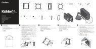
MINUET User’s <strong>Manual</strong><br />
Set Up<br />
1. Take the case out of the box. Remove the Styrofoam and the plastic bag.<br />
2. Place the case on a flat surface.<br />
3. Remove the thumbscrews from the top panel (at the rear of the case). Sli<strong>de</strong><br />
the panel to the rear of the case and remove it. Set the panel safely asi<strong>de</strong>.<br />
Note: Please don't try to use your fingernails to pry or lift the panel.<br />
4. Insi<strong>de</strong> the case you should see the power supply, some wiring with marked<br />
connectors (USB, PWR etc.), an installed I/O panel and a power cord. You<br />
will also find a bag of screws, four rubber feet and two plastic stands.<br />
Note: The plastic stands allow you to orient the Minuet in two positions –<br />
horizontal and vertical.<br />
5. Horizontal Orientation: stick the four adhesive rubber feet to the bottom<br />
panel of the case to protect the paint from scratches.<br />
6. Vertical Orientation: place the Minuet in the two plastic stands, adjust<br />
the stands to fit snugly against the case si<strong>de</strong>s.<br />
[Applicable only to mo<strong>de</strong>ls <strong>de</strong>signed for sale in the European Union: All <strong>Antec</strong><br />
power supplies <strong>de</strong>signed for the EU inclu<strong>de</strong> a Power Factor Correction (PFC)<br />
circuitry in accord with European standard regulation co<strong>de</strong> EN61000-3-2. By<br />
altering the input current wave shape, PFC improves the power factor of the<br />
power supply and results in increased energy efficiency, reduced heat loss,<br />
prolonged life for power distribution and consumption equipment, and improved<br />
output voltage stability.]<br />
Motherboard Installation<br />
This manual is not <strong>de</strong>signed to cover CPU, RAM, or expansion card installation.<br />
Please consult your motherboard manual for specific mounting instructions and<br />
troubleshooting.<br />
1. Make sure you have the appropriate I/O panel for your motherboard. If the<br />
standard panel provi<strong>de</strong>d with Minuet is not suitable for your motherboard,<br />
please contact your motherboard manufacturer for the correct I/O panel.<br />
2. Line up your motherboard with the standoff holes, and <strong>de</strong>termine which<br />
ones line up and remember where they are. Not all motherboards will<br />
match with all of the provi<strong>de</strong>d screw holes, and this is not necessary for<br />
proper functionality. (In other words there will likely be extra holes.) Some<br />
standoffs may be pre-installed for your convenience.<br />
3. Lift up and remove your motherboard.<br />
4. Screw in the brass standoffs to the threa<strong>de</strong>d holes that line up with your<br />
motherboard's mounting holes.<br />
5. Place your motherboard on the brass standoffs.<br />
6. Mount your motherboard on the standoffs with the provi<strong>de</strong>d Phillips-head<br />
screws. Your motherboard is now installed.<br />
Power/LED Connections<br />
The power supply is an ATX12V form factor power supply. It has a single 20 pin<br />
Main Power Connector and a 4-pin +12V Power Connector to connect to the<br />
motherboard. It also comes with three 4-pin Peripheral Power Connectors and<br />
one 4-pin Floppy Drive Power Connector for your drives. It is backwards compatible<br />
to previous ATX form factor power supplies. If your motherboard does not<br />
support the +12V Power Connector, you can still use this power supply.<br />
1. Connect the 20-pin ATX power connector (and +12V connector if<br />
appropriate) to your motherboard.<br />
2. Power Switch (labeled POWER SW) connects to the PWR connector on the<br />
motherboard.<br />
3. Attach the Speaker (labeled SPEAKER), Power LED (labeled P LED) and<br />
HDD LED connectors to the appropriate hea<strong>de</strong>rs on your motherboard.<br />
USB Connection<br />
There are 8 wires with connectors coming from the front-mounted USB ports.<br />
1. Locate the internal USB hea<strong>de</strong>r on your motherboard. It consists of 10 pins<br />
in two rows. Note: On some motherboards one or two pins may be marked<br />
as NC. This indicates no contact. It is an empty pin. You don't need to use<br />
it. On some motherboards one pin may be missing on either one or both<br />
rows. Don't worry about it. You only need to connect to 8 pins.<br />
2. Consult your motherboard manual to get each of the pin-out positions.<br />
3. Power Pins: There are two power pins, one on each row. They are usually<br />
marked as Power, Vcc or +5V. Connect the two +5V connectors to the<br />
two power pins. Each connector can go to either pin.<br />
4. Ground Pins: There are two ground pins, one on each row. They are usually<br />
marked as GROUND or GND. Connect the two GROUND connectors to the<br />
two ground pins. Each connector can go to either pin.<br />
Note: On some motherboards, there may be two ground pins on one row.<br />
You don't need to use all of them. Make sure to connect one ground pin<br />
on each row.<br />
5. Data Pins: There are two plus data pins, one on each row, and two minus<br />
data pins, one on each row. They are usually marked as USBD2+, USBD3+<br />
and USBD2-, USBD3- or USBP2+, USBP3+ and USBP2-, USBP3- respectively.<br />
a. Connect the (1)+D connector to any of the two plus data pins. It can<br />
go to either of the plus pins.<br />
b. Connect the (1)- D connector to the minus data pin in the same row as<br />
the plus data pin (1)+D connector.<br />
c. Repeat the same procedures to connect the (2)+D and (2)-D to the<br />
motherboard. Make sure they are in the same row.<br />
1<br />
2