Room Air Conditioner SVC MANUAL(Exploded ... - Jordans Manuals
Room Air Conditioner SVC MANUAL(Exploded ... - Jordans Manuals
Room Air Conditioner SVC MANUAL(Exploded ... - Jordans Manuals

You also want an ePaper? Increase the reach of your titles
YUMPU automatically turns print PDFs into web optimized ePapers that Google loves.
Internal Use Only<br />
http://biz.lgservice.com<br />
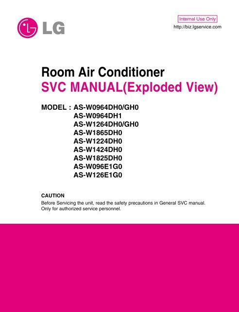
<strong>Room</strong> <strong>Air</strong> <strong>Conditioner</strong><br />
<strong>SVC</strong> <strong>MANUAL</strong>(<strong>Exploded</strong> View)<br />
MODEL : AS-W0964DH0/GH0<br />
AS-W0964DH1<br />
AS-W1264DH0/GH0<br />
AS-W1865DH0<br />
AS-W1224DH0<br />
AS-W1424DH0<br />
AS-W1825DH0<br />
AS-W096E1G0<br />
AS-W126E1G0<br />
CAUTION<br />
Before Servicing the unit, read the safety precautions in General <strong>SVC</strong> manual.<br />
Only for authorized service personnel.
<strong>Air</strong> <strong>Conditioner</strong> Service Manual<br />
TABLE OF CONTENTS<br />
LG Model Name.................................................................................................................................3<br />
Safety Precautions ...........................................................................................................................5<br />
Dimensions .....................................................................................................................................10<br />
Installation.......................................................................................................................................14<br />
Connecting the cable between indoor unit and outdoor unit.....................................................24<br />
Checking the drainage and forming the pipings .........................................................................26<br />
<strong>Air</strong> purging ......................................................................................................................................27<br />
Test running ....................................................................................................................................29<br />
Functions.........................................................................................................................................30<br />
Operation.........................................................................................................................................33<br />
Disassembly....................................................................................................................................44<br />
Troubleshooting Guide ..................................................................................................................47<br />
Schematic Diagram ........................................................................................................................67<br />
Product Specifications ..................................................................................................................76<br />
<strong>Exploded</strong> View ................................................................................................................................80<br />
Copyright ©2009 LG Electronics. Inc. All right reserved.<br />
Only for training and service purposes<br />
- 2 -<br />
LGE Internal Use Only
2003<br />
LG Model Name<br />
LG Model Name<br />
1 2 - 3 4 5 6 7 8 9 10<br />
Code Type Code of Model Meaning<br />
1 Producing Center, A~Z L: Chang-won R22 N: India<br />
Refrigerant A: Chang-won R410A Z: Brazil<br />
C: Chang-won R407C D: Indonesia<br />
T: China M: Mexico<br />
K: Turkey R22 V: Vietnam<br />
E: Turkey R410A S: Out Sourcing<br />
H: Thailand<br />
2 Product Type A~Z S: Split Type <strong>Air</strong> <strong>Conditioner</strong><br />
3 Cooling/Heating/Inverter A~Z C: Cooling only<br />
H: Heat pump<br />
X: C/O + E/Heater<br />
Z: H/P + E/Heater<br />
V: AC Inverter C/O<br />
N: AC Inverter H/P<br />
Q: DC Inverter C/O<br />
W: DC Inverter H/P<br />
4, 5 Capacity 0~9 Cooling/Heating Capacity<br />
Ex. "09" → 9,000 Btu/h<br />
6 Electric Range 1~9 1: 115V/60Hz, A: 220V, 50Hz, 3Phase<br />
A~Z 2: 220V/60Hz B: 208~230V, 60Hz, 3Phase<br />
3: 208-230V/60Hz C: 575V, 50Hz, 3Phase<br />
5: 200-220V/50Hz D: 440~460, 60Hz, 3Phase<br />
6: 220-240V/50Hz E: 265V, 60Hz<br />
7: 110V, 50/60Hz F: 200V, 50/60Hz<br />
8: 380-415V/50Hz<br />
9: 380-415V/60Hz<br />
7 Chassis A~Z Name of Chassis of Unit<br />
Ex. 4 → S4 Chassis<br />
8 Look A~Z Look,<br />
Color (Artcool Model)<br />
9 Function A~Z Basic<br />
Basic+4Way<br />
Plasma Filter<br />
Plasma Filter+4 Way<br />
Tele+LCD<br />
Tele+LCD+Nano plasma+4Way<br />
Nano Plasma F+(A/changeove)+A/clean+Low A<br />
Nano Plasma F+(A/changeove)+A/clean+4way+Low A<br />
Tele+LED+4way<br />
Internet<br />
Plasma F+4Way+Oxy generator<br />
Nano Plasma F+(A/changeove)+A/clean<br />
Nano Plasma F+(A/changeove)+A/clean+4way<br />
Nano Plasma F+(A/changeove)+A/clean+PTC<br />
Nano Plasma F+(A/changeove)+Autoclean+4way+PTC<br />
Nano Plasma F+(A/changeove)+A/clean+4way+Low A+PTC<br />
Negative ION+A/Clean<br />
(Nano)Plasma+Negative ION+A/Clean<br />
4way+(Nano)Plasma F+Negative ION+Healthy dehumidification+A/Clean<br />
Nano Plasma F+4Way+(A/changeove)+A/clean+<br />
10 Serial No. 0~9 LG Model Development Serial No.<br />
* ARTCOOL COLOR<br />
R<br />
Mirror<br />
N<br />
Walnut<br />
W<br />
White<br />
A<br />
Gogh<br />
B<br />
Blue<br />
S<br />
Sisley<br />
D<br />
Wood<br />
Q<br />
Quran<br />
M<br />
Metal<br />
K<br />
Mecca<br />
C<br />
Cherry<br />
A<br />
B<br />
C<br />
D<br />
E<br />
F<br />
G<br />
H<br />
I<br />
J<br />
K<br />
L<br />
M<br />
N<br />
P<br />
Q<br />
R<br />
S<br />
T<br />
U<br />
Copyright ©2009 LG Electronics. Inc. All right reserved.<br />
Only for training and service purposes<br />
- 3 -<br />
LGE Internal Use Only
LG Model Name<br />
2004~<br />
1 2 - 3 4 5 6 7 8 9 10<br />
Code Type Code of Model Meaning<br />
1 Producing Center, A~Z L Chang_won R22<br />
Refrigerant<br />
A Chang_won R410A<br />
C Chang_won R407C<br />
T China<br />
K Turkey R22<br />
E Turkey R410A<br />
H Thailand<br />
N India<br />
Z Brazil<br />
D Indonesia<br />
X Mexico<br />
V Vietnam<br />
S Out sourcing<br />
2 Product Type A~Z S: Split Type <strong>Air</strong> <strong>Conditioner</strong><br />
3 Cooling/Heating/Inverter A~Z C: Cooling only<br />
H: Heat pump<br />
X: C/O + E/Heater<br />
Z: H/P + E/Heater<br />
V: AC Inverter C/O<br />
N: AC Inverter H/P<br />
Q: DC Inverter C/O<br />
W: DC Inverter H/P<br />
4, 5 Capacity 0~9 Cooling/Heating Capacity<br />
Ex. "09" → 9,000 Btu/h<br />
6 Electric Range 1~9 1: 115V/60Hz, A: 220V, 50Hz, 3Phase<br />
A~Z 2: 220V/60Hz B: 208~230V, 60Hz, 3Phase<br />
3: 208-230V/60Hz C: 575V, 50Hz, 3Phase<br />
5: 200-220V/50Hz D: 440~460, 60Hz, 3Phase<br />
6: 220-240V/50Hz E: 265V, 60Hz<br />
7: 110V, 50/60Hz F: 200V, 50/60Hz<br />
8: 380-415V/50Hz<br />
CHASSIS<br />
9: 380-415V/60Hz<br />
S4/S5/SD<br />
7 Chassis A~Z Name of Chassis of Unit<br />
Ex. 4→S4 Chassis<br />
8 Look A~Z Look,<br />
Color (Artcool Model)<br />
9 Function A~Z<br />
10 Serial No. 0~9 LG Model Development Serial No.<br />
* ARTCOOL COLOR<br />
R<br />
Mirror<br />
W<br />
White<br />
B<br />
Blue<br />
D<br />
Wood<br />
M<br />
Metal<br />
C<br />
Cherry<br />
SE<br />
S6<br />
SQ<br />
SR<br />
ST<br />
Look<br />
D<br />
G<br />
1<br />
K<br />
L<br />
G<br />
M<br />
N<br />
D<br />
P<br />
Division<br />
Panel Type(Deluxe)<br />
Grille Type<br />
Panel Type(Deluxe)<br />
Fighting 'Look'<br />
(LG1)<br />
(LG2)-SEMI PANEL<br />
OEM1<br />
OEM2<br />
Panel Type(Deluxe)<br />
LG3<br />
Basic<br />
A<br />
Basic+4Way<br />
B<br />
Plasma Filter<br />
C<br />
Plasma Filter+4 Way<br />
D<br />
Tele+LCD<br />
E<br />
Tele+LCD+Nano plasma+4Way<br />
F<br />
NBF F+(A/changeove)+A/clean+Low A<br />
G<br />
NBF F+(A/changeove)+A/clean+4way+Low A<br />
H<br />
Tele+LED+4way<br />
I<br />
Internet<br />
J<br />
Plasma F+4Way+Oxy generator<br />
K<br />
NBF F+(A/changeove)+A/clean<br />
L<br />
NBF F+(A/changeove)+A/clean+4way<br />
M<br />
NBF F+(A/changeove)+A/clean+PTC<br />
N<br />
NBF F+(A/changeove)+Autoclean+4way+PTC<br />
P<br />
NBF F+(A/changeove)+A/clean+4way+Low A+PTC<br />
Q<br />
(Nano)Plasma+ION+A/Clean<br />
S<br />
4way+(Nano)Plasma F+Negative ION+Healthy dehumidification+A/Clean T<br />
Nano Plasma F+4Way+(A/changeove)+A/clean+Oxy generator<br />
U<br />
4way+(Nano)Plasma F+Negative ION+Healthy dehumidification+A/Clean+Oxy generator V<br />
Dry contact<br />
W<br />
Wire remocon 8<br />
Copyright ©2009 LG Electronics. Inc. All right reserved.<br />
Only for training and service purposes<br />
- 4 -<br />
LGE Internal Use Only
Safety Precautions<br />
Safety Precautions<br />
To prevent injury to the user or other people and property damage, the following instructions must<br />
be followed.<br />
■ Incorrect operation due to ignoring instruction will cause harm or damage. The seriousness is<br />
classified by the following indications.<br />
This symbol indicates the possibility of death or serious injury.<br />
This symbol indicates the possibility of injury or damage to properties only.<br />
■ Meanings of symbols used in this manual are as shown below.<br />
Be sure not to do.<br />
Be sure to follow the instruction.<br />
■ Installation<br />
Do not use damaged power cords, plugs, or a<br />
loose socket.<br />
• There is risk of fire of electric shock.<br />
Always use the power plug and socket with the<br />
ground terminal.<br />
• There is risk of electric shock.<br />
Install the panel and the cover of control box<br />
securely.<br />
Do not modify or extend the power cord.<br />
• There is risk of fire of electric shock.<br />
• No grounding may cause electric shock.<br />
Copyright ©2009 LG Electronics. Inc. All right reserved.<br />
Only for training and service purposes<br />
- 5 -<br />
LGE Internal Use Only
Safety Precautions<br />
For re-installation of the installed product,<br />
always contact a dealer or an authorized service<br />
center.<br />
• There is risk of fire, electric shock, explosion, or<br />
injury.<br />
Do not install, remove, or re-install the unit by<br />
yourself.<br />
• There is risk of fire, electric shock, explosion, or<br />
injury.<br />
Be cautious when unpacking and installing the<br />
product.<br />
• Sharp edges could cause injury. Be especially careful<br />
of the case edges and the fins on the condenser<br />
and evaporator.<br />
For installation, always contact the dealer or<br />
an Authorized service center<br />
• There is risk of fire, electric shock, explosion, or injury.<br />
Do not install the product on a defective installation<br />
stand.<br />
• It may cause injury, accident, or damage to the<br />
product.<br />
Be sure the installation area does not<br />
deteriorate with age.<br />
• If the base collapses, the air conditioner could fall<br />
with it, causing property damage, product failure,<br />
and personal injury.<br />
Copyright ©2009 LG Electronics. Inc. All right reserved.<br />
Only for training and service purposes<br />
- 6 -<br />
LGE Internal Use Only
Safety Precautions<br />
■ Operation<br />
Do not turn the air-conditioner ON or OFF by<br />
plugging or unplugging the power plug.<br />
• There is risk of fire or electrical shock.<br />
Use a dedicated outlet for this appliance.<br />
• There is risk of fire or electrical shock.<br />
Grasp the plug to remove the cord from the<br />
outlet. Do not touch it with wet hands.<br />
• There is risk of fire or electrical shock.<br />
Do not place a heater or other appliances near<br />
the power cable.<br />
• There is risk of fire and electric shock.<br />
Do not allow water to run into electrical parts.<br />
• There is risk of fire, failure of the product, or electric<br />
shock.<br />
Do not store or use flammable gas or combustibles<br />
near the air conditioner.<br />
• There is risk of fire or failure of product.<br />
Wax<br />
Thinner<br />
Copyright ©2009 LG Electronics. Inc. All right reserved.<br />
Only for training and service purposes<br />
- 7 -<br />
LGE Internal Use Only
Safety Precautions<br />
Unplug the unit if strange sounds, odors, or<br />
smoke comes from it.<br />
• There is risk of electric shock or fire.<br />
Be cautious that water could not enter the<br />
product.<br />
• There is risk of fire, electric shock, or product damage.<br />
■ Installation<br />
Always check for gas (refrigerant) leakage after<br />
installation or repair of product.<br />
• Low refrigerant levels may cause failure of product.<br />
Install the drain hose to ensure that water is<br />
drained away properly.<br />
• A bad connection may cause water leakage.<br />
Keep level even when installing the product.<br />
• To avoid vibration or water leakage.<br />
Use two or more people to lift and transport<br />
the air conditioner.<br />
• Avoid personal injury.<br />
90˚<br />
Copyright ©2009 LG Electronics. Inc. All right reserved.<br />
Only for training and service purposes<br />
- 8 -<br />
LGE Internal Use Only
Safety Precautions<br />
■ Operation<br />
Use a soft cloth to clean. Do not use harsh<br />
detergents, solvents, etc.<br />
• There is risk of fire, electric shock, or damage to the<br />
plastic parts of the product.<br />
Do not touch the metal parts of the product<br />
when removing the air filter. They are very<br />
sharp!<br />
• There is risk of personal injury.<br />
Wax<br />
Do not step on or put anyting on the product.<br />
(outdoor units)<br />
• There is risk of personal injury and failure of product.<br />
Do not insert hands or other objects through<br />
the air inlet or outlet while the air conditioner<br />
is plugged in.<br />
• There are sharp and moving parts that could cause<br />
personal injury.<br />
Copyright ©2009 LG Electronics. Inc. All right reserved.<br />
Only for training and service purposes<br />
- 9 -<br />
LGE Internal Use Only
Dimensions<br />
Dimensions<br />
Symbols Used in this Manual<br />
This symbol alerts you to the risk of electric shock.<br />
This symbol alerts you to hazards that could cause harm to the<br />
air conditioner.<br />
NOTICE<br />
This symbol indicates special notes.<br />
Indoor Unit<br />
H<br />
W<br />
D<br />
Type 1.<br />
Installation plate<br />
Type 2.<br />
Installation plate<br />
Model<br />
7k, 9k, 12k, 14k Btu Series<br />
Dimension<br />
W mm 840 895<br />
H mm 270 282<br />
D mm 153 165<br />
Copyright ©2009 LG Electronics. Inc. All right reserved.<br />
Only for training and service purposes<br />
- 10 -<br />
LGE Internal Use Only
Dimensions<br />
H<br />
W<br />
D<br />
Type 1.<br />
Installation plate<br />
Type 2.<br />
Installation plate<br />
Model<br />
18k, 24k Btu Series<br />
Dimension<br />
W mm 1090<br />
H mm 300<br />
D mm 178<br />
Copyright ©2009 LG Electronics. Inc. All right reserved.<br />
Only for training and service purposes<br />
- 11 -<br />
LGE Internal Use Only
Dimensions<br />
Outdoor Unit<br />
W<br />
L2<br />
L1<br />
D<br />
L3<br />
L5<br />
H<br />
Gas side<br />
(3-way valve)<br />
L4<br />
Liquid side<br />
(2-way valve)<br />
MODEL<br />
DIM<br />
unit<br />
7k, 9k, 12k, 14k Btu Series<br />
W mm 770<br />
H mm 540<br />
D mm 245<br />
L1 mm 285<br />
L2 mm 65<br />
L3 mm 518<br />
L4 mm 10<br />
L5 mm 100<br />
Copyright ©2009 LG Electronics. Inc. All right reserved.<br />
Only for training and service purposes<br />
- 12 -<br />
LGE Internal Use Only
Dimensions<br />
W<br />
H<br />
L4<br />
L3<br />
D<br />
L10<br />
L2<br />
L11<br />
L5<br />
L1<br />
Gas side<br />
Liquid side<br />
L7 L6 L8 L9<br />
MODEL<br />
DIM<br />
18k, 24k Btu Series<br />
W mm 870<br />
H mm 655<br />
D mm 320<br />
L1 mm 370<br />
L2 mm 340<br />
L3 mm 25<br />
L4 mm 630<br />
L5 mm 25<br />
L6 mm 546<br />
L7 mm 162<br />
L8 mm 162<br />
L9 mm 54<br />
L10 mm 74.5<br />
L11 mm 79<br />
Copyright ©2009 LG Electronics. Inc. All right reserved.<br />
Only for training and service purposes<br />
- 13 -<br />
LGE Internal Use Only
Installation<br />
Installation<br />
Select the best Location<br />
Indoor unit<br />
1. Do not have any heat or steam near the unit.<br />
2. Select a place where there are no obstacles in front<br />
of the unit.<br />
3. Make sure that condensation drainage can be conveniently<br />
routed away.<br />
4. Do not install near a doorway.<br />
5. Ensure that the interval between a wall and the left<br />
(or right) of the unit is more than 10cm. The unit<br />
should be installed as high as possible on the wall,<br />
allowing a minimum of 20cm from ceiling.<br />
6. Use a stud finder to locate studs to prevent unnecessary<br />
damage to the wall.<br />
More than<br />
10cm<br />
More than 1.5m<br />
More than 20cm<br />
More than<br />
10cm<br />
Install the indoor unit on the wall where the height from the floor is more than 1.5 meters.<br />
Outdoor unit<br />
1. If an awning is built over the unit to prevent direct<br />
sunlight or rain exposure, make sure that heat radiation<br />
from the condenser is not restricted.<br />
2. Ensure that the space around the back and sides is<br />
more than 30cm. The front of the unit should have<br />
more than 70cm of space.<br />
3. Do not place animals and plants in the path of the<br />
warm air.<br />
4. Take the weight of the air conditioner into account<br />
and select a place where noise and vibration are minimum.<br />
5. Select a place where the warm air and noise from the<br />
air conditioner do not disturb neighbors.<br />
More than 30cm<br />
More than 70cm<br />
More than 60cm<br />
More than 30cm<br />
More<br />
than 60cm<br />
Copyright ©2009 LG Electronics. Inc. All right reserved.<br />
Only for training and service purposes<br />
- 14 -<br />
LGE Internal Use Only
A<br />
Installation<br />
Piping Length and Elevation<br />
Capacity<br />
Pipe Size<br />
(Btu/h) GAS LIQUID<br />
Standard<br />
Length (m)<br />
Max.<br />
Elevation B (m)<br />
Max.<br />
Length A (m)<br />
Additional Refrigerant<br />
(g/m)<br />
7k, 8k, 9k 3/8" 1/4" 4 or 7.5 7 15 20<br />
11k, 12k, 14k<br />
3/8" 1/4" 4 or 7.5 7 15 20<br />
1/2" 1/4" 4 or 7.5 7 15 20<br />
1/2" 1/4" 4 or 7.5 15 30 20<br />
18k, 24k, 26k 5/8" 1/4" 4 or 7.5 15 30 20<br />
5/8" 3/8" 4 or 7.5 15 30 30<br />
Indoor unit<br />
Outdoor unit<br />
Outdoor unit<br />
A<br />
Oil trap<br />
A<br />
B<br />
Outdoor unit<br />
Indoor unit<br />
B<br />
Indoor unit<br />
B<br />
If the piping length is more<br />
10 Meters and the outdoor<br />
Capacity is based on standard length and maximum allowance length is on the basis of reliability.<br />
Oil trap should be installed every 5~7 meters.<br />
Copyright ©2009 LG Electronics. Inc. All right reserved.<br />
Only for training and service purposes<br />
- 15 -<br />
LGE Internal Use Only
Installation<br />
Fixing Installation Plate<br />
The wall you select should be strong and solid<br />
enough to prevent vibration<br />
1. Mount the installation plate on the wall with<br />
type "A" screws. If mounting the unit on a concrete<br />
wall, use anchor bolts.<br />
• Mount the installation plate horizontally by aligning<br />
the centerline using a level.<br />
Chassis<br />
Hook<br />
Installation Plate<br />
Type "A" screw<br />
2. Measure the wall and mark the centerline. It is also<br />
important to use caution concerning the location of<br />
the installation plate-routing of the wiring to power<br />
outlets is through the walls typically. Drilling the<br />
hole through the wall for piping connections must<br />
be done safely.<br />
Type 1.<br />
Type 1.<br />
CHASSIS<br />
(Grade)<br />
Distance (mm)<br />
A B C D<br />
S4 73 55 82 55<br />
S5 121 62 258 62<br />
D<br />
Ø70mm<br />
C<br />
Left rear piping<br />
Installation plate<br />
A<br />
Right rear piping<br />
B<br />
Ø70mm<br />
Type 2.<br />
Type 2.<br />
CHASSIS<br />
Distance (mm)<br />
(Grade) A B C D<br />
S4 50 105 59 105<br />
SE 65 110 85 110<br />
S5 95 122 235 122<br />
D<br />
Installation plate<br />
B<br />
Ø70mm<br />
C<br />
Left rear piping<br />
A<br />
Right rear piping<br />
Ø70mm<br />
Drill a Hole in the Wall<br />
• Drill the piping hole with a ø70mm hole core drill.<br />
Drill the piping hole at either the right or the left with<br />
the hole slightly slanted to the outdoor side.<br />
Indoor<br />
WALL<br />
Outdoor<br />
5-7mm<br />
(3/16"~5/16")<br />
Copyright ©2009 LG Electronics. Inc. All right reserved.<br />
Only for training and service purposes<br />
- 16 -<br />
LGE Internal Use Only
Installation<br />
Flaring Work<br />
Main cause for gas leakage is due to defect in flaring work. Carry out correct flaring work in the following procedure.<br />
Cut the pipes and the cable.<br />
1. Use the piping kit accessory or the pipes purchased locally.<br />
2. Measure the distance between the indoor and the outdoor<br />
unit.<br />
3. Cut the pipes a little longer than measured distance.<br />
4. Cut the cable 1.5m longer than the pipe length.<br />
Copper<br />
pipe 90° Slanted Uneven Rough<br />
Burrs removal<br />
1. Completely remove all burrs from the cut cross section of<br />
pipe/tube.<br />
2. Put the end of the copper tube/pipe in a downward direction<br />
as you remove burrs in order to avoid dropping burrs into the<br />
tubing.<br />
Pipe<br />
Reamer<br />
Point down<br />
Putting nut on<br />
• Remove flare nuts attached to indoor and outdoor unit, then<br />
put them on pipe/tube having completed burr removal.<br />
(not possible to put them on after flaring work)<br />
Flare nut<br />
Copper tube<br />
Flaring work<br />
1. Firmly hold copper pipe in a die in the dimension shown in the table below.<br />
2. Carry out flaring work with the flaring tool.<br />
Outside diameter<br />
A<br />
mm inch mm<br />
Ø6.35 1/4" 1.1~1.3<br />
Ø9.52 3/8" 1.5~1.7<br />
Ø12.7 1/2" 1.6~1.8<br />
Ø15.88 5/8" 1.6~1.8<br />
Ø19.05 3/4" 1.9~2.1<br />
Bar<br />
"A"<br />
Copper pipe<br />
Bar<br />
Handle<br />
Yoke<br />
Cone<br />
Clamp handle<br />
Red arrow mark<br />
Copyright ©2009 LG Electronics. Inc. All right reserved.<br />
Only for training and service purposes<br />
- 17 -<br />
LGE Internal Use Only
Installation<br />
Check<br />
1. Compare the flared work with the figure by.<br />
2. If a flared section is defective, cut it off and do flaring<br />
work again.<br />
Smooth all round<br />
Inside is shiny without scratches<br />
= Improper flaring =<br />
Even length<br />
all round<br />
Inclined<br />
Surface Cracked Uneven<br />
damaged thickness<br />
Connecting the Piping<br />
Indoor<br />
1. Prepare the indoor unit's piping and drain hose for installation through the wall.<br />
2. Remove the plastic tubing retainer(see the illustration<br />
by) and pull the tubing and drain hose away from<br />
chassis.<br />
3. Replace only the plastic tubing holder 1, not the holder<br />
2 in the original position.<br />
For right rear piping<br />
1. Route the indoor tubing and the drain hose in the<br />
direction of rear right.<br />
2. Insert the connecting cable into the indoor unit from the<br />
outdoor unit through the piping hole.<br />
• Do not connect the cable to the indoor unit.<br />
• Make a small loop with the cable for easy connection<br />
later.<br />
3. Tape the tubing, drain hose, and the connecting<br />
cable. Be sure that the drain hose is located at the<br />
lowest side of the bundle. Locating at the uper side<br />
can cause drain pan to overflow inside the unit.<br />
If the drain hose is routed inside the room, insulate the<br />
hose with an insulation material* so that dripping from<br />
"sweating"(condensation) will not damage furniture or<br />
floors.<br />
*Foamed polyethylene or equivalent is recommended.<br />
Tape<br />
Connecting<br />
pipe<br />
Drain hose<br />
Drain hose<br />
Connecting cable<br />
Copyright ©2009 LG Electronics. Inc. All right reserved.<br />
Only for training and service purposes<br />
- 18 -<br />
LGE Internal Use Only
Installation<br />
4. Indoor unit installation<br />
Hook the indoor unit onto the upper portion of the<br />
installation plate.(Engage the two hooks of the rear<br />
top of the indoor unit with the upper edge of the<br />
installation plate.) Ensure that the hooks are properly<br />
seated on the installation plate by moving it left and<br />
right.<br />
Connecting<br />
cable<br />
Drain hose<br />
Press the lower left and right sides of the unit against<br />
the installation plate until the hooks engage into their<br />
slots(clicking sound).<br />
Connecting the piping to the indoor unit and drain<br />
hose to drain pipe.<br />
1. Align the center of the pipes and sufficiently tighten<br />
the flare nut by hand.<br />
2. Tighten the flare nut with a wrench.<br />
Outside diameter<br />
Torque<br />
mm inch kg.m<br />
Ø6.35 1/4" 1.1~1.3<br />
Ø9.52 3/8" 1.5~1.7<br />
Ø12.7 1/2" 1.6~1.8<br />
Ø15.88 5/8" 1.6~1.8<br />
Ø19.05 3/4" 1.9~2.1<br />
Indoor unit tubing Flare nut Pipes<br />
Open-end wrench (fixed)<br />
Flare nut<br />
Wrench<br />
Connection pipe<br />
Indoor unit tubing<br />
Type "B" screw<br />
Drain hose<br />
Clamp<br />
Boss<br />
3. Mount the clamp on the boss with a type "B"<br />
screw.(optional)<br />
4. When extending the drain hose at the indoor unit,<br />
install the drain pipe.<br />
Drain pipe<br />
Indoor unit drain hose<br />
Adhesive<br />
Vinyl tape(narrow)<br />
Wrap the insulation material around the connecting<br />
portion.<br />
1. Overlap the connection pipe insulation material and<br />
the indoor unit pipe insulation material. Bind them<br />
together with vinyl tape so that there may be no gap.<br />
2. Wrap the area which accommodates the rear piping<br />
housing section with vinyl tape.<br />
Connection pipe<br />
Plastic bands<br />
Insulation material<br />
Vinyl tape (wide)<br />
Wrap with vinyl tape<br />
Connecting cable<br />
Indoor unit pipe<br />
3. Bundle the piping and drain hose together by wrapping<br />
them with vinyl tape for enough to cover where<br />
they fit into the rear piping housing section.<br />
Vinyl tape(narrow)<br />
Wrap with vinyl tape<br />
Pipe<br />
Pipe<br />
Drain hose<br />
Vinyl tape(wide)<br />
Copyright ©2009 LG Electronics. Inc. All right reserved.<br />
Only for training and service purposes<br />
- 19 -<br />
LGE Internal Use Only
Installation<br />
For left rear piping<br />
1. Route the indoor tubing and the drain hose to the<br />
required piping hole position.<br />
2. Insert the piping, drain hose, and the connecting<br />
cable into the piping hole.<br />
3. Insert the connecting cable into the indoor unit.<br />
• Don't connect the cable to the indoor unit.<br />
• Make a small loop with the cable for easy connection<br />
later.<br />
4. Tape the drain hose and the connecting cables.<br />
1 2<br />
Connecting<br />
cable<br />
Drain pipe<br />
5. Indoor unit installation<br />
• Hang the indoor unit from the hooks at the top of the<br />
installation plate.<br />
• Insert the spacer etc. between the indoor unit and<br />
the installation plate and separate the bottom of the<br />
indoor unit from the wall.<br />
Indoor unit<br />
Installation plate<br />
8cm<br />
Spacer<br />
Connecting the piping to the indoor unit and the<br />
drain hose to drain pipe.<br />
1. Align the center of the pipes and sufficiently tighten<br />
the flare nut by hand.<br />
Indoor unit tubing Flare nut Pipes<br />
2. Tighten the flare nut with a wrench.<br />
Outside diameter<br />
Torque<br />
mm inch kg.m<br />
Ø6.35 1/4" 1.1~1.3<br />
Ø9.52 3/8" 1.5~1.7<br />
Ø12.7 1/2" 1.6~1.8<br />
Ø15.88 5/8" 1.6~1.8<br />
Ø19.05 3/4" 1.9~2.1<br />
3. When extending the drain hose at the indoor unit,<br />
install the drain pipe.<br />
Wrench<br />
Indoor unit tubing<br />
Drain hose<br />
Open-end wrench (fixed)<br />
Flare nut<br />
Connection pipe<br />
Vinyl tape<br />
Adhesive<br />
Indoor unit drain hose<br />
(narrow)<br />
Copyright ©2009 LG Electronics. Inc. All right reserved.<br />
Only for training and service purposes<br />
- 20 -<br />
LGE Internal Use Only
Installation<br />
Wrap the insulation material around the connecting<br />
portion.<br />
1. Overlap the connection pipe heat insulation and the<br />
indoor unit pipe heat insulation material. Bind them<br />
together with vinyl tape so that there may be no gap.<br />
2. Wrap the area which accommodates the rear piping<br />
housing section with vinyl tape.<br />
Connection<br />
pipe<br />
Vinyl tape<br />
(wide)<br />
Plastic bands<br />
Insulation material<br />
Wrap with vinyl tape<br />
Pipe<br />
Indoor<br />
unit piping<br />
Connecting cable<br />
Vinyl tape(narrow)<br />
3. Bundle the piping and drain hose together by wrapping<br />
them with cloth tape over the range within which<br />
they fit into the rear piping housing section.<br />
Drain hose<br />
Pipe<br />
Vinyl tape(narrow)<br />
Wrap with<br />
vinyl tape(wide)<br />
Reroute the pipings and the drain hose across the<br />
back of the chassis.<br />
Indoor unit installation<br />
1. Remove the spacer.<br />
2. Ensure that the hooks are properly seated on the<br />
installation plate by moving it left and right.<br />
3. Press the lower left and right sides of the unit against<br />
the installation plate until the hooks engage into their<br />
slots(clicking sound).<br />
Piping for<br />
passage through<br />
piping hole<br />
Connecting<br />
cable<br />
Drain hose<br />
Copyright ©2009 LG Electronics. Inc. All right reserved.<br />
Only for training and service purposes<br />
- 21 -<br />
LGE Internal Use Only
Installation<br />
Installation Information. For left piping. Follow the instruction below.<br />
Good case<br />
• Press on the upper side of clamp and unfold the tubing to downward slowly.<br />
Bad case<br />
• Following bending type from right to left may cause damage to the tubing.<br />
Copyright ©2009 LG Electronics. Inc. All right reserved.<br />
Only for training and service purposes<br />
- 22 -<br />
LGE Internal Use Only
Installation<br />
Outdoor<br />
Align the center of the pipings and sufficiently tighten<br />
the flare nut by hand.<br />
Finally, tighten the flare nut with torque wrench until the<br />
wrench clicks.<br />
• When tightening the flare nut with torque wrench,<br />
ensure the direction for tightening follows the arrow on<br />
the wrench.<br />
Outside diameter<br />
Torque<br />
mm inch kgf.m<br />
Ø6.35mm 1/4" 1.8~2.5<br />
Ø9.52mm 3/8" 3.4~4.2<br />
Ø12.7mm 1/2" 5.5~6.6<br />
Ø15.88mm 5/8" 6.3~8.2<br />
Ø19.05mm 3/4" 9.9~12.1<br />
Outdoor unit<br />
Liquid side piping<br />
(Smaller diameter)<br />
Torque wrench<br />
Gas side<br />
piping<br />
(Bigger<br />
diameter)<br />
Copyright ©2009 LG Electronics. Inc. All right reserved.<br />
Only for training and service purposes<br />
- 23 -<br />
LGE Internal Use Only
Connecting the cable between indoor unit and outdoor unit<br />
Connecting the cable between indoor unit and outdoor unit<br />
Connect the cable to the Indoor unit.<br />
Connect the cable to the indoor unit by connecting the wires to the terminals on the control board individually<br />
according to the outdoor unit connection. (Ensure that the color of the wires of the outdoor unit and the terminal No.<br />
are the same as those of the indoor unit.)<br />
• The above circuit diagram is subject to change without notice.<br />
• The earth wire should be longer than the common wires.<br />
• When installing, refer to the circuit diagram behind the panel front of the indoor unit.<br />
• Connect the wires firmly so that they may not be pulled out easily.<br />
• Connect the wires according to color codes, referring to the wiring diagram.<br />
Main power source<br />
If a power plug is not used, provide a circuit<br />
breaker between power source and the unit as<br />
shown by.<br />
<strong>Air</strong><br />
<strong>Conditioner</strong><br />
Circuit Breaker<br />
Use a circuit<br />
breaker or time<br />
delay fuse.<br />
The power cord connected to the "A" unit should be selected according to the following specifications(Type "B"<br />
approved by HAR or SAA).<br />
(mm 2 )<br />
Grade<br />
NORMAL CROSS<br />
-SECTIONAL AREA<br />
7k 9k~14k 18k 24k<br />
0.75 1.0 1.5 2.5<br />
Unit(A) Indoor Indoor Indoor Indoor<br />
Cable Type(B) H05VV-F H05VV-F H05VV-F H05VV-F<br />
The power connecting cable connecting the indoor and outdoor unit should be selected according to the following<br />
specifications (Type "B" approved by HAR or SAA).<br />
(mm 2 )<br />
Grade<br />
NORMAL CROSS<br />
-SECTIONAL AREA<br />
7k 9k~14k 18k 24k<br />
0.75 1.0 1.5 2.5<br />
Cable Type(B) H07RN-F H07RN-F H07RN-F H07RN-F<br />
Copyright ©2009 LG Electronics. Inc. All right reserved.<br />
Only for training and service purposes<br />
- 24 -<br />
LGE Internal Use Only
Connecting the cable between indoor unit and outdoor unit<br />
Connect the cable to the outdoor unit<br />
Remove the control cover from the unit by<br />
loosening the screw.<br />
Connect the wires to the terminals on the control<br />
board individually.<br />
Outdoor Unit<br />
Terminal block<br />
Over 5mm<br />
Secure the cable onto the control board with<br />
the cord clamp.<br />
Connecting cable<br />
Connecting cable<br />
Refix the control cover to the original position<br />
with the screw.<br />
Cover control<br />
Use a recognized circuit breaker "A"<br />
between the power source and the unit.<br />
A disconnecting device to adequately disconnect<br />
all supply lines must be fitted.<br />
Circuit<br />
Breaker<br />
(A)<br />
Grade<br />
5k~14k 18k 24k~28k 30k, 32k 36k, 38k<br />
15 20 30 30 40<br />
After the confirmation of the above conditions, prepare the wiring as follows:<br />
1) Never fail to have an individual power circuit specifically for the air conditioner. As for the method of wiring,<br />
be guided by the circuit diagram posted on the inside of control cover.<br />
2) The screw which fasten the wiring in the casing of electrical fittings are liable to come loose from vibrations<br />
to which the unit is subjected during the course of transportation. Check them and make sure that they are<br />
all tightly fastened. (If they are loose, it could cause burn-out of the wires.)<br />
3) Specification of power source.<br />
4) Confirm that electrical capacity is sufficient.<br />
5) See to that the starting voltage is maintained at more than 90 percent of the rated voltage marked on the<br />
name plate.<br />
6) Confirm that the cable thickness is as specified in the power source specification.<br />
(Particularly note the relation between cable length and thickness. (Refer to page 21))<br />
7) Always install an earth leakage circuit breaker in a wet or moist area.<br />
8) The following would be caused by voltage drop.<br />
• Vibration of a magnetic switch, which will damage the contact point, fuse breaking, disturbance of the normal function<br />
of the overload.<br />
9) The means for disconnection from a power supply shall be incorporated in the fixed wiring and have an air<br />
gap contact separation of at least 3mm in each active(phase) conductors.<br />
Copyright ©2009 LG Electronics. Inc. All right reserved.<br />
Only for training and service purposes<br />
- 25 -<br />
LGE Internal Use Only
Checking the drainage and forming the pipings<br />
Checking the drainage and forming the pipings<br />
Checking the drainage<br />
To remove the front panel from the indoor unit.<br />
• Set the air direction louvers up-and-down to the<br />
position(horizontally)by hand.<br />
• Remove the securing screws that retain the front panel.<br />
Pull the lower left and right sides of the grille toward you<br />
and lift it off.<br />
Pull the right and<br />
the left side.<br />
To check the drainage.<br />
• Pour a glass of water on the evaporator.<br />
• Ensure the water flows through the drain hose of the indoor<br />
unit without any leakage and goes out the drain exit.<br />
Form the piping<br />
Form the piping by wrapping the connecting<br />
portion of the indoor unit with insulation material<br />
and secure it with two kinds of vinyl tapes.<br />
• If you want to connect an additional drain hose, the end of<br />
the drain outlet should be routed above the ground. Secure<br />
the drain hose appropriately.<br />
In cases where the outdoor unit is installed<br />
below the indoor unit perform the following.<br />
• Tape the piping, drain hose and connecting cable from<br />
down to up.<br />
• Secure the tapped piping along the exterior wall using saddle<br />
or equivalent.<br />
Seal small openings<br />
around pipings with a<br />
gum type sealer.<br />
Taping<br />
Drain<br />
hose<br />
Pipings<br />
Connecting<br />
cable<br />
Drain piping<br />
• The drain hose should point downward for easy drain flow.<br />
Downward slope<br />
Trap is required to prevent water<br />
from entering into electrical parts.<br />
In cases where the Outdoor unit is installed<br />
above the Indoor unit perform the following.<br />
• Tape the piping and connecting cable from down to up.<br />
• Secure the taped piping along the exterior wall. Form a trap<br />
to prevent water entering the room.<br />
• Fix the piping onto the wall by saddle or equivalent.<br />
Seal a small opening<br />
around the pipings<br />
with gum type sealer.<br />
Trap<br />
• Do not make drain piping.<br />
Do not raise<br />
Accumulated<br />
drain water<br />
<strong>Air</strong><br />
Tip of drain hose<br />
dipped in water<br />
Less than<br />
50mm gap<br />
Trap<br />
Water<br />
leakage<br />
Water<br />
leakage<br />
Waving<br />
Water<br />
leakage<br />
Ditch<br />
Copyright ©2009 LG Electronics. Inc. All right reserved.<br />
Only for training and service purposes<br />
- 26 -<br />
LGE Internal Use Only
<strong>Air</strong> purging<br />
<strong>Air</strong> Purging<br />
<strong>Air</strong> purging<br />
<strong>Air</strong> and moisture remaining in the refrigerant system have<br />
undesirable effects as indicated below.<br />
• Pressure in the system rises.<br />
• Operating current rises.<br />
• Cooling(or heating) efficiency drops.<br />
• Moisture in the refrigerant circuit may freeze and block capillary<br />
tubing.<br />
• Water may lead to corrosion of parts in the refrigeration<br />
system.<br />
Therefore, the indoor unit and tubing between the indoor and<br />
outdoor unit must be leak tested and evacuated to remove<br />
any noncondensables and moisture from the system.<br />
<strong>Air</strong> purging with vacuum pump<br />
Preparation<br />
• Check that each tube(both liquid and gas side tubes)<br />
between the indoor and outdoor units have been properly<br />
connected and all wiring for the test run has been completed.<br />
Remove the service valve caps from both the gas and<br />
the liquid side on the outdoor unit. Note that both the liquid<br />
and the gas side service valves on the outdoor unit are<br />
kept closed at this stage.<br />
Leak test<br />
• Connect the manifold valve(with pressure gauges) and dry<br />
nitrogen gas cylinder to this service port with charge hoses.<br />
Be sure to use a manifold valve for air purging. If it is not<br />
available, use a stop valve for this purpose. The "Hi" knob<br />
of the manifold valve must always be kept close.<br />
• Pressurize the system to no more than 150 P.S.I.G. with<br />
dry nitrogen gas and close the cylinder valve when the<br />
gauge reading reached 150 P.S.I.G. Next, test for leaks<br />
with liquid soap.<br />
• Do a leak test of all joints of the tubing(both indoor and outdoor)<br />
and both gas and liquid side service valves.<br />
Bubbles indicate a leak. Be sure to wipe off the soap with a<br />
clean cloth.<br />
• After the system is found to be free of leaks, relieve the<br />
nitrogen pressure by loosening the charge hose connector<br />
at the nitrogen cylinder. When the system pressure is<br />
reduced to normal, disconnect the hose from the cylinder.<br />
Pressure<br />
gauge<br />
Manifold valve<br />
Lo<br />
Indoor unit<br />
Outdoor unit<br />
Hi<br />
Charge hose<br />
To avoid nitrogen entering the refrigerant system in a liquid<br />
state, the top of the cylinder must be higher than its bottom<br />
when you pressurize the system. Usually, the cylinder is<br />
used in a vertical standing position.<br />
Nitrogen gas<br />
cylinder(in vertical<br />
standing position)<br />
Copyright ©2009 LG Electronics. Inc. All right reserved.<br />
Only for training and service purposes<br />
- 27 -<br />
LGE Internal Use Only
<strong>Air</strong> purging<br />
Soap water method<br />
(1) Remove the caps from the 2-way and 3-way valves.<br />
(2) Remove the service-port cap from the 3-way valve.<br />
(3) To open the 2-way valve turn the valve stem counterclockwise<br />
approximately 90°, wait for about 2~3 sec, and<br />
close it.<br />
(4) Apply a soap water or a liquid neutral detergent on the<br />
indoor unit connection or outdoor unit connections by a<br />
soft brush to check for leakage of the connecting points<br />
of the piping.<br />
(5) If bubbles come out, the pipes have leakage.<br />
Evacuation<br />
• Connect the charge hose end described in the preceding<br />
steps to the vacuum pump to evacuate the tubing and<br />
indoor unit.<br />
Confirm the "Lo" knob of the manifold valve is open. Then,<br />
run the vacuum pump.<br />
The operation time for evacuation varies with tubing length<br />
and capacity of the pump. The following table shows the<br />
time required for evacuation.<br />
Required time for evacuation when 30 gal/h vacuum<br />
pump is used<br />
3-way valve<br />
(Close)<br />
2-way valve<br />
(Open)<br />
Gas side<br />
Liquid side<br />
Cap<br />
Hexagonal wrench<br />
Indoor unit<br />
If tubing length is less than 10m (33 ft)<br />
if tubing length is longer than 10m (33 ft)<br />
10 min. or more 15 min. or more<br />
Outdoor unit<br />
• When the desired vacuum is reached, close the "Lo" knob<br />
of the manifold valve and stop the vacuum pump.<br />
Finishing the job<br />
• With a service valve wrench, turn the valve stem of liquid<br />
side valve counter-clockwise to fully open the valve.<br />
• Turn the valve stem of gas side valve counter-clockwise to<br />
fully open the valve.<br />
• Loosen the charge hose connected to the gas side service<br />
port slightly to release the pressure, then remove the hose.<br />
• Replace the flare nut and its bonnet on the gas side service<br />
port and fasten the flare nut securely with an adjustable<br />
wrench. This process is very important to prevent leakage<br />
from the system.<br />
• Replace the valve caps at both gas and liquid side service<br />
valves and fasten them tight.<br />
This completes air purging with a vacuum pump.<br />
The air conditioner is now ready to test run.<br />
Pressure<br />
gauge<br />
Open<br />
Manifold valve<br />
Lo<br />
Hi<br />
Vacuum pump<br />
Close<br />
Copyright ©2009 LG Electronics. Inc. All right reserved.<br />
Only for training and service purposes<br />
- 28 -<br />
LGE Internal Use Only
Test running<br />
Test Running<br />
1. Check that all tubing and wiring have been properly connected.<br />
2. Check that the gas and liquid side service valves are fully<br />
open.<br />
Settlement of outdoor unit<br />
• Anchor the outdoor unit with a bolt and nut(ø10mm) tightly<br />
and horizontally on a concrete or rigid mount.<br />
• When installing on the wall, roof or rooftop, anchor the<br />
mounting base securely with a nail or wire assuming the<br />
influence of wind and earthquake.<br />
• In the case when the vibration of the unit is conveyed to the<br />
hose, secure the unit with an anti-vibration bushing.<br />
Bolt<br />
Evaluation of the performance<br />
Operate unit for 15~20 minutes, then check the system<br />
refrigerant charge:<br />
1. Measure the pressure of the gas side service valve.<br />
2. Measure the temperature of the intake and discharge of air.<br />
3. Ensure the difference between the intake temperature and<br />
the discharge is more than 8°C(46°F) (Cooling) or<br />
(Heating).<br />
Discharge air<br />
Tubing connection<br />
Intake temperature<br />
NOTE: If the actual pressure is higher than shown, the system is<br />
most likely over-charged, and charge should be removed.<br />
If the actual pressure are lower than shown, the system is<br />
most likely undercharged, and charge should be added.<br />
The air conditioner is now ready for use.<br />
PUMP DOWN<br />
This is performed when the unit is to be relocated or<br />
the refrigerant circuit is serviced.<br />
Pump Down means collecting all refrigerant in the outdoor<br />
unit without loss in refrigerant gas.<br />
CAUTION:<br />
Be sure to perform Pump Down procedure with the unit<br />
cooling mode.<br />
Pump Down Procedure<br />
1. Connect a low-pressure gauge manifold hose to the<br />
charge port on the gas side service valve.<br />
2. Open the gas side service valve halfway and purge the air<br />
from the manifold hose using the refrigerant gas.<br />
3. Close the liquid side service valve(all the way in).<br />
4. Turn on the unit's operating switch and start the cooling<br />
operation.<br />
5. When the low-pressure gauge reading becomes 1 to<br />
0.5kg/cm2 G(14.2 to 7.1 P.S.I.G.), fully close the gas side<br />
valve stem and then quickly turn off the unit. At that time,<br />
Pump Down has been completed and all refrigerant gas<br />
will have been collected in the outdoor unit.<br />
Power-Failure Compensation Function User Selection ON/OFF<br />
1) Operation Sequence<br />
Press the forced switch until BUZZER sounds 2 times<br />
(beep~beep~).<br />
Release the forced switch if BUZZER sounds.<br />
Check the function selection ON/OFF with the operation LED.<br />
Discharge<br />
temperature<br />
4. For reference; the gas side pressure of optimum condition<br />
is as below.(Cooling)<br />
2) Checking function-selection ON/OFF<br />
- Function-Selection ON: One time blinking of operation LED<br />
would repeat 4 times.<br />
- Function-Selection OFF: Two times blinking of operation LED<br />
would repeat 4 times.<br />
Refrigerant<br />
Outside ambient<br />
TEMP.<br />
The pressure of the gas side<br />
service valve.<br />
R-22 35°C (95°F) 4~5kg/cm 2 G(56.8~71.0 P.S.I.G.)<br />
R-410A 35°C (95°F) 8.5~9.5kg/cm 2 G(120~135 P.S.I.G.)<br />
Power<br />
button<br />
Copyright ©2009 LG Electronics. Inc. All right reserved.<br />
Only for training and service purposes<br />
- 29 -<br />
LGE Internal Use Only
Functions<br />
Functions<br />
Indoor Unit<br />
Cooling Mode Operation<br />
Healty dehumidification Mode Operation<br />
Heating Mode Operation<br />
Jet Cool Mode Operation<br />
Jet Heat Mode Operation<br />
Energy Saving Cooling Mode Operation<br />
Operation ON/OFF by Remote controller<br />
Sensing the <strong>Room</strong> Temperature<br />
• <strong>Room</strong> temperature sensor. (Thermistor)<br />
• Pipe temperature sensor. (Thermistor)<br />
<strong>Room</strong> temperature control<br />
• Maintain the room temperature in accordance with the Setting Temp.<br />
Starting the Current Control<br />
• Indoor fan is delayed for 5 sec at the starting.<br />
Time Delay Safety Control<br />
• Restarting is for approx. 2 minutes.<br />
Indoor Fan Speed Control<br />
• Super High, High, Med, Low<br />
Operation indication Lamps (LED)<br />
--- Lights up in operation<br />
--- Lights up in Timer Mode or Sleep Mode<br />
--- Lights up in Preheat Mode or Defrost Mode<br />
--- Lights up in Plasma <strong>Air</strong> Clean Mode<br />
--- Lights up in during Energy-Saving Cooling Mode Operation (Optional)<br />
Copyright ©2009 LG Electronics. Inc. All right reserved.<br />
Only for training and service purposes<br />
- 30 -<br />
LGE Internal Use Only
Functions<br />
Sleep Mode Auto Control<br />
• The fan is switched to S-Low(Cooling), low(Heating) speed.<br />
• The unit will be stopped after 1, 2, 3, 4, 5, 6, 7 hours.<br />
Natural <strong>Air</strong> Control by CHAOS Logic<br />
• The fan is switched to intermittent or irregular operation<br />
• The fan speed is automatically switched from high to low speed.<br />
<strong>Air</strong>flow Direction Control<br />
• The louver can be set at the desired position or swing up and down automatically.<br />
Auto Changeover<br />
Energy-Saving Control(Optional)<br />
Horizontal airflow Direction Control(Optional)<br />
Auto Clean(Optional)<br />
Plasma<br />
• The function will be operated while in any operation mode with selecting the function.<br />
• The function is to be stopped while it isoperating with selecting the function.<br />
Defrost(Deice) Control (Heating)<br />
• Both the indoor and outdoor fan stops during defrosting.<br />
Hot-start Control (Heating)<br />
• The indoor fan stops until the evaporator pipe temperature will be reached at 30°C.<br />
Heater (Optional)<br />
Copyright ©2009 LG Electronics. Inc. All right reserved.<br />
Only for training and service purposes<br />
- 31 -<br />
LGE Internal Use Only
Functions<br />
Outdoor Unit<br />
Power Relay Control<br />
• If power is on, it will operate to chage capacitor on controller and power relay will operate after about 2~5sec.<br />
Active Power Filter Control(PSC)<br />
• The active power filter is designed to correct power factor(cos θ) and to regulate DC link voltage.<br />
• It will be operated PFC circuit when the compressor freq. is over 30Hz and wattage is over 450 watt.<br />
Comp. Freq. Control<br />
• The final operating freq. of comp. is set the lowest freq. that limited outdoor temp., discharge pipe temp.,<br />
heat-sink temp., target freq., owing to CT.<br />
OverheatIng. Protection(Power Module)<br />
• When the temp. of power module increases to 85°C, controller decreases Freq. of Comp.<br />
Freq. Speed Control(Up/Down Speed)<br />
• It will be changed the drive freq. of comp. according to temp. of indoor and outdoor.<br />
Total Current Control (Over Current Protection)<br />
DC Peak Current Control<br />
4 way Valve Control<br />
• It is only operated in the heating operation mode except defrosting operation.<br />
Outdoor Fan Motor Control<br />
• High speed<br />
- Although fan motor speed is middle, it will change high speed in case of below AC193V, over 40°C (Cooling<br />
Mode) of outdoor temp. below 4°C(Heating Mode) of outdoor temp., and over fc, fh of comp. Freq.<br />
• Middle speed<br />
- Nomal mode<br />
• Low speed<br />
- Although fan motor speed is middle, it will change Low speed in case of over AC 270V, over 21°C<br />
(Heating Mode) of outdoor temp. below 24°C (Cooling Mode) of outdoor temp.<br />
Discharge Pipe Temp. Control<br />
Low Ambient<br />
Comp. Torque Control<br />
Over Heating Protection (Comp.)<br />
Copyright ©2009 LG Electronics. Inc. All right reserved.<br />
Only for training and service purposes<br />
- 32 -<br />
LGE Internal Use Only
Operation<br />
Function of Controls<br />
• DISPLAY<br />
1) C/O Model<br />
Operation<br />
Operation Indicator<br />
• ON while in appliance operation, OFF while in appliance pause.<br />
• Flashing while in disconnection or short in Thermistor. (3 sec off / 0.5 sec on)<br />
Timer Indicator<br />
• ON while in timer mode (on/off), OFF when timer mode is completed or canceled.<br />
Comp. Running Incidator<br />
• While in appliance operation, ON while in outdoor unit compressor running, OFF while in compressor off.<br />
2) H/P Model<br />
Operation Indicator<br />
• ON while in appliance operation, OFF while in appliance pause.<br />
• Flashing while in disconnection or short in Thermistor. (3 sec off / 0.5 sec on)<br />
Timer Indicator<br />
• ON while in timer mode (on/off), OFF when timer mode is completed or canceled.<br />
Defrost Indicator<br />
• OFF except when hot start during heating mode operation or while in defrost control.<br />
Protection of the evaporator pipe from frosting<br />
• If the indoor pipe temperaure is below 0°C in 7 min. after the compressor operates without pause while in<br />
cooling cycle operation mode,<br />
➔ compressor, outdoor fan are turned off.<br />
• When indoor pipe temp. is 7°C or higher after 2 min pause of compressor<br />
➔ compressor, outdoor fan is turned on according to the condition of the room temperature.<br />
6˚C<br />
3˚C<br />
0˚C<br />
Comp. Step 4<br />
Comp. Step 2<br />
Comp. free<br />
Comp. off<br />
Indoor pipe<br />
temp.<br />
7˚C<br />
Copyright ©2009 LG Electronics. Inc. All right reserved.<br />
Only for training and service purposes<br />
- 33 -<br />
LGE Internal Use Only
Operation<br />
Cooling mode operation<br />
• Operating frequency of compressor depend on the difference of the temperature.<br />
(= intake air Temp.- Compressor off Temp.<br />
• Compressor off temp.= setting temp. -0.5°C<br />
on temp. = setting temp. +0.5°C<br />
• If compressor operates at some operating frequency, the operating frequency of compressor cannot be<br />
changed within 30 seconds.<br />
• Condition of compressor turned off<br />
- When intake air temperature stay at the temperature between setting temp. -0.5°C and setting temp.<br />
-1.0°C for 3 minutes continuously.<br />
- When intake air temperature reaches below the temperature of setting temp. -1.0°C.<br />
• Compressor 2 minutes delay<br />
- The compressor can restart minimum 2 minutes later after compressor off.<br />
[The operating freq. step of comp.]<br />
Temp. differences<br />
Comp. Operating frequency<br />
over 2.5°C Step 7<br />
2.0~2.49°C Step 6<br />
1.5~1.99°C Step 5<br />
1.0~1.49°C Step 4<br />
0.5~0.99°C Step 3<br />
0.0~0.49°C Step 2<br />
-0.5~0°C Step 1<br />
[The targeting operating freq. of comp. each model]<br />
Model<br />
Comp. Operating frequency<br />
Step 1 Step 2 Step 3 Step 4 Step 5(Fc) Step 6 Step 7<br />
AS-W0964DH0/DH1/GH0 35 39 43 47 52 57 62<br />
AS-W1264DH0/GH0 20 35 47 56 63 70 78<br />
AS-W1865DH0 16 32 58 64 70 75 85<br />
AS-W1224DH0 20 35 47 54 65 70 74<br />
AS-W1424DH0 20 35 47 54 72 74 78<br />
AS-W1825DH0 16 32 53 62 72 75 85<br />
AS-W096E1G0 25 35 40 52 56 74 82<br />
AS-W126E1G0 25 35 40 52 66 74 82<br />
Healthy Dehumidification mode operation<br />
• When the dehumidification operation is set by the remote controller the intake air temperature is detected and<br />
the setting temp. is automatically set according to the intake air temperature.<br />
Intake air Temp.<br />
26°C ≤ intake air temp.<br />
24°C ≤ intake air temp.< 26°C<br />
18°C < intake air temp. < 24°C<br />
intake air temp. ≤ 18°C<br />
Setting Temp.<br />
25°C<br />
intake air temp. -1°C<br />
intake air temp. -0.5°C<br />
18°C<br />
• When intake air temp reaches above the temp of setting +1.0°C, condition of compressor same as cooling<br />
mode operation.<br />
• When intake air temperature reaches bolow the temp of setting –1.0°C, compressor operate step1~step3 and<br />
indoor fan speed repeatly operate low or stop.<br />
Copyright ©2009 LG Electronics. Inc. All right reserved.<br />
Only for training and service purposes<br />
- 34 -<br />
LGE Internal Use Only
Operation<br />
Heating mode operation<br />
• Operating frequency of compressor depend on the difference of the temperature<br />
(= compressor off temp. - intake air temp.)<br />
• Compressor off temp. = setting temp. +4°C<br />
on temp. = setting temp. +2°C<br />
• If compressor operates at some operation frequency, the operating frequency of compressor cannot be<br />
changed within 30 seconds.<br />
• Condition of compressor turned off<br />
- When intake air temperature reaches +4°C above the setting temperature.<br />
• Condition of indoor fan turned off<br />
- While in compressor on:indoor pipe temp. < 20°C<br />
• While in defrost control, between the indoor and outdoor fans are turned off.<br />
• Compressor 2minutes delay<br />
- After compressor off, the compressor can restart minimum 2 minutes later.<br />
[ The operating freq. step of comp]<br />
Temp. differences<br />
Comp. Operating frequency<br />
2.5~3.0°C<br />
2.0~2.49°C<br />
1.5~1.99°C<br />
1.0~1.49°C<br />
0.5~0.99°C<br />
0.0~0.49°C<br />
-0.5~0°C<br />
Step 1<br />
Step 2<br />
Step 3<br />
Step 4<br />
Step 5<br />
Step 6<br />
Step 7<br />
Model<br />
[The targeting operating freq. of comp. each model]<br />
AS-W0964DH0/DH1/GH0 35 44 53 62 69 74 80<br />
AS-W1264DH0/GH0 20 38 53 63 72 79 86<br />
AS-W1865DH0 16 38 47 65 79 87 96<br />
AS-W1224DH0 20 35 53 63 70 79 86<br />
AS-W1424DH0 20 35 53 63 77 79 86<br />
AS-W1825DH0 16 38 47 62 79 87 90<br />
AS-W096E1G0 35 40 48 56 65 90 94<br />
AS-W126E1G0 35 40 48 56 80 90 94<br />
Jet cool mode operation<br />
Comp. Operating frequency<br />
Step 1 Step 2 Step 3 Step 4 Step 5 Step 6 Step 7<br />
• While in heating mode or Fuzzy operation, the Jet Cool key cannot be input. When it is input while in the<br />
other mode operation(cooling, dehumidification, ventilation), the Jet Cool mode is operated.<br />
• In the Jet Cool mode, the indoor fan is operated super-high speed for 30 min. at cooling mode operation.<br />
• In the Jet Cool mode, the room temperature is controlled to the setting temperature, 18°C.<br />
• When the sleep timer mode input while the Jet Cool mode operation, the Jet Cool mode has the priority.<br />
• When the Jet Cool key is input, the upper/lower vane is reset to those of the initial cooling mode and then<br />
operated in order that the air outflow could reach further.<br />
Copyright ©2009 LG Electronics. Inc. All right reserved.<br />
Only for training and service purposes<br />
- 35 -<br />
LGE Internal Use Only
Operation<br />
Jet heat mode operation<br />
• While in cooling mode or Fuzzy operation, the Jet Heat key cannot be input. When it is input while in the<br />
Heating mode operation (dehumidification), the Jet Heat mode is operated.<br />
• In the Jet Heat mode, the indoor fan is operated super-high speed for 60 min. at Heating mode operation.<br />
• In the Jet Heat mode, the room temperature is controlled to the setting temperature, 30°C.<br />
• When the sleep timer mode input while the Jet Heat mode operation, the Jet Heat mode has the priority.<br />
• When the Jet Heat key is input, the upper/lower vane is reset to those of the initial Jet heating mode and<br />
then operated in order that the air outflow could reach under flow.<br />
Swing mode<br />
1. New Chaos swing mode<br />
• By the Chaos swing key input, the upper/lower vane automatically operates with the Chaos swing or it is<br />
fixed to the desired direction.<br />
(S4, SE) 7, 9, 12, 14k Model<br />
CLOSED<br />
Cooling Operation<br />
CLOSED<br />
Heating Operation<br />
Mode8<br />
110°<br />
Mode8<br />
110°<br />
Mode7<br />
Mode7<br />
Start<br />
Mode6<br />
Mode6<br />
Mode5<br />
Mode5<br />
Mode4<br />
Mode4<br />
Mode3<br />
Start<br />
Mode3<br />
Mode2<br />
Mode1<br />
8°<br />
Mode2<br />
Mode1<br />
8°<br />
OPEN<br />
OPEN<br />
(S5) 18, 24k Model<br />
CLOSED<br />
Cooling Operation<br />
CLOSED<br />
Heating Operation<br />
Start<br />
Mode9<br />
Mode8<br />
Mode7<br />
Mode6<br />
Mode5<br />
Mode4<br />
Mode3<br />
Mode2<br />
Mode1<br />
120°<br />
8°<br />
Start<br />
Mode9<br />
Mode8<br />
Mode7<br />
Mode6<br />
Mode5<br />
Mode4<br />
Mode3<br />
Mode2<br />
8°<br />
120°<br />
OPEN<br />
OPEN<br />
Copyright ©2009 LG Electronics. Inc. All right reserved.<br />
Only for training and service purposes<br />
- 36 -<br />
LGE Internal Use Only
Operation<br />
Sleep timer operation<br />
• When the sleep time is reached after [1,2,3,4,5,6,7hr] is input by the remote control during the operation, the<br />
operation of the appliance stops.<br />
• When the appliance is on pause, the sleep timer mode cannot be input.<br />
1. Sleep timer operation for cooling cycle<br />
• While in cooling mode operation, 30 min. later since the start of the sleep timer, the setting temperature<br />
increase by 1°C. After another 30min. elapse, it increases by 1°C again.<br />
Setting temp. (˚C)<br />
1.0˚C up<br />
1.0˚C up<br />
Cooling ON temp.<br />
(Setting temp. +0.5˚C)<br />
Cooling OFF temp.<br />
(Setting temp. -0.5˚C)<br />
0.5 1 Sleep time (hr)<br />
2. Sleep timer operation for heating cycle<br />
• While in heating mode operation, 60 min. later since the start of the sleep timer, the setting temperature<br />
decrease by 1°C. After another 60min. elapse, it decreases by 1°C again.<br />
Setting temp. (°C)<br />
Heating ON temp.<br />
(Setting temp. +2°C)<br />
1.0°C down<br />
Heating OFF temp.<br />
(Setting temp. +4°C)<br />
1.0°C down<br />
1 2 Sleep time (hr)<br />
Copyright ©2009 LG Electronics. Inc. All right reserved.<br />
Only for training and service purposes<br />
- 37 -<br />
LGE Internal Use Only
Operation<br />
Auto restarting operation<br />
• When the power is restarted after a sudden power failure while in appliance operation, the mode before the<br />
power failure is kept on the memory and the appliance automatically operates in the mode on the memory.<br />
• Operation mode that is kept on the memory<br />
- State of operation ON/OFF<br />
- Operation mode/setting temp./selected airflow speed<br />
- Sleep timer mode/remaining time of sleep timer<br />
- Chaos Swing<br />
Forced operation<br />
• To operate the appliance by force in case that the remote control is lost, the forced operation selection switch<br />
is on the main unit of the appliance to operate the appliance in the standard conditions.<br />
• The operation condition is set according to the outdoor temp. and intake air temperature as follows.<br />
Indoor temp.<br />
Operating Mode<br />
Setting temp.<br />
Setting speed of<br />
indoor fan<br />
over 24°C<br />
Cooling<br />
22°C<br />
21~24°C<br />
Healthy Dehumidification<br />
23°C<br />
High speed<br />
below 21°C<br />
Heating<br />
❈ The unit select before operating mode in 3 hours.<br />
24°C<br />
Test Operation<br />
• Press the Tact Switch for compulsory operation of the main body for 3 seconds in order to operate in the trial<br />
operation mode.<br />
- Operation mode: Cold<br />
- Indoor pan: Strong wind<br />
- COMP frequency: Step 5<br />
- COMP compulsorily operates for about 18 minutes irrespective of indoor temperature.<br />
Copyright ©2009 LG Electronics. Inc. All right reserved.<br />
Only for training and service purposes<br />
- 38 -<br />
LGE Internal Use Only
Operation<br />
Power relay control<br />
• Power relay turns on 1 second later after the power is input to the outdoor unit.<br />
• Control sequence : power on ➔ PTC operating ➔ power relay on<br />
Protection from total current control<br />
■ CT1 control<br />
• If the operating current reaches I1, the operating frequency of the compressor decrease.<br />
• After decreasing the operating frequency by 1step, if operating current is below I1 for 60 seconds continuously,<br />
the operating frequency of compressor increase by 1step.<br />
■ CT2 control<br />
• If the operating current of the appliance reaches I2, the compressor stop instantly and 2 minutes later the<br />
compressor restart again.<br />
• If CT2 occurs 5 times within 1hour, the appliance turn off and display ERROR CODE 7.<br />
Control table<br />
❇ I1:Current of operating frequency down<br />
I2: Current of compressor cut off<br />
I1<br />
Model<br />
Outdoor temp ≥ 38°C Outdoor temp < 38°C I2<br />
Cooling Heating Cooling Heating<br />
1 AS-W096DH0/DH1/GH0 5.5 6.5 6 7 9<br />
2 AS-W126DH0/GH0 6.5 7.5 7 8 10<br />
3 AS-W1865DH0 9 10.5 9.5 11 13<br />
4 AS-W1224DH0 6 6.5 6.5 7 8.5<br />
5 AS-W1424DH0 6 6.5 6.5 7 9<br />
6 AS-W1825DH0 10.5 11.5 11 12 14<br />
7 AS-W096E1G0 7 8.5 7.5 9 10<br />
8 AS-W126E1G0 7 8.5 7.5 9 10<br />
cf. I1 is set the lowest level between intial value and in case dectection of dc paeak current.<br />
Protection from DC Peak Current<br />
■ DC Peak Current Error by a fault signal of IPM<br />
• If the operating current of IPM reaches 35A ±3A, the compressor stop instantly.<br />
• If DC PEAK occurs 5 times within 1 hour, the appliance turns off and display ERROR CODE 6.<br />
■ DC Peak Current Error by the compressor lock<br />
• If the DC LINK voltage below DC 140V occurs 5 times within 1 hour while the compressor is operating, the<br />
appliance turns off and display ERROR CODE 6.<br />
■ DC Peak Current Error by the Outdoor Fan Lock<br />
• If it’s 5 times within 1 hour in case of the temperature of outdoor pipe TH is over 65°C while the compressor is<br />
operating, the appliance turns off and display ERROR CODE 6.<br />
Copyright ©2009 LG Electronics. Inc. All right reserved.<br />
Only for training and service purposes<br />
- 39 -<br />
LGE Internal Use Only
Operation<br />
Portection from overheating of power module<br />
• If the temperature of the heat sink TH. reaches over Toff, the Compressor stop instantly.<br />
• It will be limited the compressor operating frequency according to the heat sink TH.(refer to below FIG.)<br />
• It will be blink 4 times, when the thermistor is open or short, also the temperature is over Toff.<br />
T off °C<br />
∆T = (T off - T on)<br />
T1 = T on + ∆T<br />
T2 = T on + 2 * ∆T<br />
Heat Sink Temp.<br />
No. MODEL T on T off<br />
1 AS-W0964DH0/DH1/GH0 95 105<br />
2 AS-W1264DH0/GH0 95 105<br />
T2 °C<br />
3 AS-W1865DH0 85 95<br />
4 AS-W1224DH0 85 95<br />
T1 °C<br />
5 AS-W1424DH0 85 95<br />
6 AS-W1825DH0 85 95<br />
T on °C<br />
7 AS-W096E1G0 85 95<br />
8 AS-W126E1G0 85 95<br />
COMP<br />
Freq.<br />
Free Fc-1 Fc-2 Fc-1 Fc-2 OFF Free<br />
Portection from overheating of compressor<br />
• If the temperature of the discharge pipe of compressor reaches over 130°C or below -30°C the compressor<br />
stop instantly.<br />
• It will be limited the compressor operating frequency according to the compressor dome TH.(Refer to below<br />
Fig.)<br />
• Temperature range by COMP SPEC varies by 10°C.<br />
T off °C<br />
T3 °C<br />
D-Pipe Temp.<br />
∆T = (T off - T2)/2<br />
T1 = T2 - 2 * ∆T<br />
T3 = T2 + ∆T<br />
No. MODEL T on T off<br />
1 AS-W0964DH0/DH1/GH0 95 105<br />
2 AS-W1264DH0/GH0 95 105<br />
T2 °C<br />
3 AS-W1865DH0 98 108<br />
4 AS-W1224DH0 95 105<br />
5 AS-W1424DH0 95 105<br />
T1 °C<br />
6 AS-W1825DH0 98 108<br />
7 AS-W096E1G0 100 110<br />
-13 °C<br />
8 AS-W126E1G0 100 110<br />
COMP Freq. Fh min Free Fc-1 Fc-2 OFF Fc-2 Fc-1 Free<br />
Copyright ©2009 LG Electronics. Inc. All right reserved.<br />
Only for training and service purposes<br />
- 40 -<br />
LGE Internal Use Only
Operation<br />
Defrosting control<br />
• While in heating mode operation in order to protect the evaporator pipe of the outdoor unit from freezing,<br />
reversed to cooling cycle to defrost the evaporator pipe of the outdoor unit.<br />
• Defrosting control is available 50 minutes later since heating cycle started and the pipe temperature of outdoor<br />
unit reaches below -6°C.<br />
Operating<br />
Freq. of<br />
Comp.<br />
Minimum Time<br />
of Heating<br />
Setting Freq.<br />
Main Deice time<br />
Setting<br />
Freq.<br />
Fh<br />
min<br />
Fh<br />
min<br />
Fh<br />
min<br />
EEV<br />
Open step<br />
Setting<br />
Starting step<br />
4-Way<br />
ON<br />
ON<br />
Outdoor<br />
FAN<br />
Indoor<br />
FAN<br />
Setting<br />
Speed<br />
Setting<br />
Speed<br />
OFF<br />
OFF<br />
Hi Speed<br />
Hot<br />
Start<br />
Setting<br />
Speed<br />
Hot<br />
Starting<br />
Pre-Heat<br />
LED<br />
OFF<br />
ON<br />
OFF<br />
Deice STEP<br />
0 1 2 3 4 5 6<br />
Copyright ©2009 LG Electronics. Inc. All right reserved.<br />
Only for training and service purposes<br />
- 41 -<br />
LGE Internal Use Only
Operation<br />
Auto Cleaning<br />
• Function used to perform the Self Cleaning to prevent the Unit from Fungus and Bad Odors.<br />
• Used after the Shut Down of Cooling Operation to Clean the Evaporator and keep it as fresh for the Next operation.<br />
• During Self Cleaning the Outdoor Unit is Switched off.<br />
• The function is easy to be operated as It is accessed through the Remote Controller.<br />
1) Heat/pump Model<br />
ON<br />
OFF<br />
2) Cooling/only Model<br />
ON<br />
OFF<br />
Cooling CYCLE<br />
Fan<br />
Heating<br />
Fan<br />
Cooling CYCLE<br />
Fan<br />
13 Min 60 Sec 120 Sec<br />
Comp.<br />
ON<br />
OFF ON OFF<br />
Indoor Fan Setting Step Low Low Low<br />
Comp.<br />
Indoor Fan<br />
ON<br />
Setting Step<br />
30 Min<br />
OFF<br />
Low<br />
Auto Changeover<br />
• The air conditioner changes the operation<br />
mode automatically to keep indoor temperature.<br />
• When room temperature vary over ±2°C with<br />
respect to setting temperature, air conditioner<br />
keeps the room temperature in ±2°C with<br />
respect to setting temperature by auto<br />
change mode.<br />
+2°C<br />
+1°C<br />
+0.5°C<br />
Set Temp.<br />
-0.5°C<br />
-1°C<br />
-2°C<br />
Outdoor temp.<br />
Indoor temp.<br />
Outdoor<br />
temp.<br />
30°C<br />
20°C<br />
Auto<br />
Change<br />
Mode.<br />
COOLING<br />
HEATING<br />
10°C<br />
Low Ambient<br />
• If outdoor temperature drops below certain temperature,liquid back is prevented by reducing fan speed.<br />
It can prevent frosting of evaporator and keep cooling operation<br />
• No matter even if the outdoor temperature reaches -10°C.<br />
• You can Cool your room at your desired temperature all your around.<br />
Freq.<br />
On<br />
Off<br />
On<br />
Off<br />
- 0°C °…<br />
Outdoor fan<br />
Comp Freq.<br />
Outdoor pipe temp.<br />
0°C ° outdoor fan On/Off<br />
control<br />
Outdoor temp.<br />
Temp.(°C)<br />
25<br />
20<br />
15<br />
10<br />
5<br />
0<br />
-5<br />
Cond . temp.<br />
Outdoor temp.:-10°C<br />
Outdoor fan On/Off control<br />
0 50 100 150 200<br />
Time(Min.)<br />
Copyright ©2009 LG Electronics. Inc. All right reserved.<br />
Only for training and service purposes<br />
- 42 -<br />
LGE Internal Use Only
Operation<br />
Remote Control Operations<br />
The controls will look like the following.<br />
5<br />
6<br />
4<br />
2<br />
7<br />
11<br />
8<br />
13<br />
15<br />
ON<br />
OFF<br />
Operation Mode<br />
CANCEL<br />
SET<br />
AUTO CLEAN<br />
Cooling Operation<br />
Auto Operation or Auto Changeover<br />
Healthy Dehumidification Operation<br />
Heating Operation<br />
Signal transmitter<br />
1<br />
3<br />
10<br />
9<br />
12<br />
14<br />
16<br />
Flip-up door<br />
(opened)<br />
• Cooling Model( ), Heat Pump Model( )<br />
17<br />
1. START/STOP BUTTON<br />
Operation starts when this button is pressed and<br />
stops when the button is pressed again.<br />
2. OPERATION MODE SELECTION BUTTON<br />
Used to select the operation mode.<br />
3. ROOM TEMPERATURE SETTING BUTTONS<br />
Used to select the room temperature.<br />
4. INDOOR FAN SPEED SELECTOR<br />
Used to select fan speed in four steps<br />
low, medium, high and CHAOS.<br />
5. JET COOL/JET HEAT<br />
Used to start or stop the speed cooling/heating.<br />
(speed cooling/heating operates super high fan speed in<br />
cooling/heating mode.)<br />
6. CHAOS SWING BUTTON<br />
Used to stop or start louver movement and set<br />
the desired up/down airflow direction.<br />
7. ON/OFF TIMER BUTTONS<br />
Used to set the time of starting and stopping operation.<br />
8. TIME SETTING BUTTONS<br />
Used to adjust the time.<br />
9. TIMER SET/CANCEL BUTTON<br />
Used to set the timer when the desired time is obtained<br />
and to cancel the Timer operation.<br />
10. SLEEP MODE AUTO BUTTON<br />
Used to set Sleep Mode Auto operation.<br />
11. ENERGY-SAVING COOLING MODE BUTTON<br />
(OPTIONAL)<br />
Used to set Energy-Save in cooling mode.<br />
12. ROOM TEMPERATURE CHECKING BUTTON<br />
Used to check the room temperature.<br />
13. PLASMA(OPTIONAL)<br />
Used to start or stop the plasma function.<br />
14. HORIZONTAL AIRFLOW DIRECTION CONTROL<br />
BUTTON (OPTIONAL)<br />
Used to set the desired horizontal airflow direction.<br />
15. RESET BUTTON<br />
Used prior to resetting time.<br />
16. 2ND F BUTTON<br />
Used prior to using modes printed in blue at the bottom of<br />
buttons.<br />
17. AUTO CLEAN (OPTIONAL)<br />
Used to set Auto Clean mode.<br />
Copyright ©2009 LG Electronics. Inc. All right reserved.<br />
Only for training and service purposes<br />
- 43 -<br />
LGE Internal Use Only
Disassembly<br />
Disassembly<br />
Indoor Unit<br />
Disconnect the unit from power supply before making<br />
any checks.<br />
Be sure the power switch is set to “OFF”.<br />
To remove the Grille from the Chassis.<br />
• Set the up-and-down air discharge louver to open<br />
position (horizontally) by finger pressure.<br />
• Remove the securing screws.<br />
• To remove the Grille, pull the lower left and right<br />
side of the grille toward you (slightly tilted) and lift it<br />
straight upward.<br />
1. Before removing the control box, be sure to<br />
take out the wire screwed at the other end.<br />
Earth<br />
Conductor<br />
Copyright ©2009 LG Electronics. Inc. All right reserved.<br />
Only for training and service purposes<br />
- 44 -<br />
LGE Internal Use Only
Disassembly<br />
2. To remove the Control Box.<br />
• Remove securing screws.<br />
• Pull the control box out from the chassis<br />
carefully.<br />
Screw<br />
3. To remove the Discharge Grille.<br />
• Unhook the discharge grille and pull the<br />
discharge grille out from the chassis carefully.<br />
4. To remove the Evaporator.<br />
• Remove 3 screws securing the evaporator(at the<br />
left 2EA in the Eva Holder, at the right 1EA).<br />
• When repair, do not damage the Caution label.<br />
Copyright ©2009 LG Electronics. Inc. All right reserved.<br />
Only for training and service purposes<br />
- 45 -<br />
LGE Internal Use Only
Disassembly<br />
• Unhook the tab on the right inside of the chassis<br />
at the same time, slightly pull the evaporator<br />
toward you until the tab is clear of the slot.<br />
5. To remove the Motor Cover<br />
• Remove 2 securing screw.<br />
• Pull the motor cover out from the chassis<br />
carefully.<br />
Motor cover<br />
6. To remove the Cross-Flow Fan<br />
• Loosen the screw securing the cross-flow fan to<br />
the fan motor (do not remove).<br />
• Lift up the right side of the cross-flow fan and the<br />
fan motor, separate the fan motor from the<br />
cross-flow fan.<br />
Bearing<br />
Cross-flow fan<br />
• Remove the left end of the cross-flow fan from<br />
the self-aligning bearing.<br />
Copyright ©2009 LG Electronics. Inc. All right reserved.<br />
Only for training and service purposes<br />
- 46 -<br />
LGE Internal Use Only
Troubleshooting Guide<br />
Troubleshooting Guide<br />
Refrigeration Cycle Diagram<br />
(1) Model Capillary Tube<br />
INDOOR UNIT<br />
OUTDOOR UNIT<br />
LIQUID SIDE<br />
3-WAY VALVE<br />
HEAT<br />
EXCHANGE<br />
(EVAPORATOR)<br />
HEAT<br />
EXCHANGE<br />
(CONDENSER)<br />
GAS SIDE<br />
3-WAY VALVE<br />
ACCUMU<br />
LATOR<br />
REVERSING<br />
VALVE<br />
COMPRESSOR<br />
COOLING<br />
HEATING<br />
(2) Model Adopted Electronic Expansion Valve<br />
INDOOR UNIT<br />
OUTDOOR UNIT<br />
LIQUID SIDE<br />
3-WAY VALVE<br />
EEV<br />
HEAT<br />
EXCHANGE<br />
(EVAPORATOR)<br />
HEAT<br />
EXCHANGE<br />
(CONDENSER)<br />
GAS SIDE<br />
3-WAY VALVE<br />
ACCUMU<br />
LATOR<br />
REVERSING<br />
VALVE<br />
COMPRESSOR<br />
COOLING<br />
HEATING<br />
Copyright ©2009 LG Electronics. Inc. All right reserved.<br />
Only for training and service purposes<br />
- 47 -<br />
LGE Internal Use Only
Troubleshooting Guide<br />
2-way, 3-way Valve<br />
2-way Valve (Liquid Side)<br />
3-way Valve (Gas Side)<br />
Flare nut<br />
To<br />
piping<br />
connection<br />
To outdoor unit<br />
Hexagonal wrench (4mm)<br />
Open position<br />
Closed position<br />
Flare nut<br />
To<br />
piping<br />
connection<br />
Valve cap<br />
Open position<br />
Closed position<br />
Service<br />
port cap<br />
To outdoor unit<br />
Pin<br />
Service<br />
port<br />
1.<br />
2.<br />
3.<br />
4.<br />
5.<br />
6.<br />
Works<br />
Shipping<br />
<strong>Air</strong> purging<br />
(Installation)<br />
Operation<br />
Pumping down<br />
(Transfering)<br />
Evacuation<br />
(Servicing)<br />
Gas charging<br />
(Servicing)<br />
Pressure check<br />
(Servicing)<br />
Gas releasing<br />
(Servicing)<br />
Shaft position Shaft position Service port<br />
Closed Closed Closed<br />
(with valve cap) (with valve cap) (with cap)<br />
Open Closed Open<br />
(counter-clockwise) (clockwise) (push-pin or with<br />
vacumm pump)<br />
Open Open Closed<br />
(with valve cap) (with valve cap) (with cap)<br />
Closed Open Open<br />
(clockwise) (counter-clockwise) (connected manifold<br />
gauge)<br />
Open Open Open<br />
(with charging<br />
cylinder)<br />
Open Open Open<br />
(with charging<br />
cylinder)<br />
Open<br />
Open<br />
Open<br />
Open<br />
Open<br />
(with charging cylinder)<br />
Open<br />
(with charging cylinder)<br />
Copyright ©2009 LG Electronics. Inc. All right reserved.<br />
Only for training and service purposes<br />
- 48 -<br />
LGE Internal Use Only
Troubleshooting Guide<br />
<strong>Air</strong> purging<br />
Required tools : hexagonal wrench, adjustable wrench,<br />
torque wrenches, wrench to hold the<br />
joints, and gas leak detector.<br />
The additional gas for air purging has been charged<br />
in the outdoor unit.<br />
However, if the flare connections have not be done<br />
correctly and there gas leaks, a gas cylinder and the<br />
charge set will be needed.<br />
The air in the indoor unit and in the piping must be<br />
purged. If air remains in the refrigeration pipes, it will<br />
affect the compressor, reduce to cooling capacity,<br />
and could lead to a malfunction.<br />
Indoor unit<br />
Liquid side<br />
Open<br />
2-way<br />
valve<br />
Outdoor unit<br />
Gas side<br />
3-way<br />
valve<br />
Clsed<br />
Service port nut:<br />
Be sure, using a torque wrench to tighten the service port nut (after using the service port), so that it prevents the<br />
gas leakage from the refrigeration cycle.<br />
CAUTION: Do not leak the gas in the air during <strong>Air</strong> purging.<br />
• Procedure<br />
(1) Recheck the piping connections.<br />
(2) Open the valve stem of the 2-way valve counterclockwise<br />
approximately 90°, wait 10 seconds,<br />
and then set it to closed position.<br />
– Be sure to use a hexagonal wrench to operate<br />
the valve stem.<br />
(3) Check for gas leakage.<br />
– Check the flare connections for gas leakage.<br />
(4) Purge the air from the system.<br />
– Set the 2-way valve to the open position and<br />
remove the cap from the 3-way valve’s service<br />
port.<br />
– Using the hexagonal wrench to press the valve<br />
core pin, discharge for three seconds and then<br />
wait for one minute. Repeat this three times.<br />
(5) Use torque wrench to tighten the service port<br />
nut to a torque of 1.8kg.cm.<br />
Copyright ©2009 LG Electronics. Inc. All right reserved.<br />
Only for training and service purposes<br />
- 49 -<br />
(6) Set the 3-way valve to the back seat.<br />
(7) Mount the valve stem nuts to the 2-way and 3-<br />
way valves.<br />
(8) Check for gas leakage.<br />
– At this time, especially check for gas leakage<br />
from the 2-way and 3-way valve’s stem nuts,<br />
and from the service port nut.<br />
CAUTION: If gas leakage are discovered<br />
in step (3) above, take the following<br />
mesures :<br />
If the gas leaks stop when the piping connections<br />
are tightened further, continue working from step (4).<br />
If the gas leaks do not stop when the connections<br />
are retightened, repair the location of the leak, discharge<br />
all of the gas through the service port, and<br />
then recharge with the specified amount of gas from<br />
a gas cylinder.<br />
LGE Internal Use Only
Troubleshooting Guide<br />
Pumping Down<br />
Indoor unit<br />
Liquid side<br />
2-Way<br />
valve<br />
Open<br />
Outdoor unit<br />
Gas side<br />
3-Way<br />
valve<br />
Closed<br />
CLOSE<br />
Purge the air<br />
Lo<br />
CLOSE<br />
• Procedure<br />
(1) Confirm that both the 2-way and 3-way valves<br />
are set to the open position.<br />
– Remove the valve stem caps and confirm that<br />
the valve stems are in the raised position.<br />
– Be sure to use a hexagonal wrench to operate<br />
the valve stems.<br />
(2) Operate the unit for 10 to 15 minutes.<br />
(3) Stop operation and wait for 3 minutes, then<br />
connect the charge set to the service port of<br />
the 3-way valve.<br />
– Connect the charge hose with the push pin to<br />
the service port.<br />
(6) Operate the air conditioner at the cooling<br />
cycle and stop it when the gauge indicates<br />
1kg/cm 2 g.<br />
(7) Immediately set the 3-way valve to the closed<br />
position.<br />
– Do this quickly so that the gauge ends up indicating<br />
3 to 5kg/cm 2 g.<br />
(8) Disconnect the charge set, and mount the 2-<br />
way and 3-way valve’s stem nuts and the service<br />
port nut.<br />
– Use torque wrench to tighten the service port<br />
nut to a torque of 1.8 kg.m.<br />
– Be sure to check for gas leakage.<br />
(4) <strong>Air</strong> purging of the charge hose.<br />
– Open the low-pressure valve on the charge set<br />
slightly to air purge from the charge hose.<br />
(5) Set the 2-way valve to the closed position.<br />
Copyright ©2009 LG Electronics. Inc. All right reserved.<br />
Only for training and service purposes<br />
- 50 -<br />
LGE Internal Use Only
Troubleshooting Guide<br />
Re-air Purging<br />
(Re-installation)<br />
Indoor unit<br />
Liquid side<br />
3-Way<br />
valve<br />
Closed<br />
Outdoor unit<br />
Gas cylinder<br />
Gas side<br />
3-Way<br />
valve<br />
Closed<br />
R22<br />
OPEN<br />
Lo<br />
CLOSE<br />
• Procedure<br />
(1) Confirm that both the liquid side valve and the<br />
gas side valve are set to the closed position.<br />
(2) Connect the charge set and a gas cylinder to<br />
the service port of the Gas side valve.<br />
– Leave the valve on the gas cylinder closed.<br />
(3) <strong>Air</strong> purging.<br />
– Open the valves on the gas cylinder and the<br />
charge set. Purge the air by loosening the flare<br />
nut on the liquid side valve approximately 45°<br />
for 3 seconds then closing it for 1 minute;<br />
repeat 3 times.<br />
– After purging the air, use a torque wrench to<br />
tighten the flare nut on liquid side valve.<br />
(6) Disconnect the charge set and the gas cylinder,<br />
and set the Liquid side and Gas side<br />
valves to the open position.<br />
– Be sure to use a hexagonal wrench to operate<br />
the valve stems.<br />
(7) Mount the valve stem nuts and the service<br />
port nut.<br />
– Use torque wrench to tighten the service port<br />
nut to a torque of 1.8 kg.m.<br />
– Be sure to check for gas leakage.<br />
CAUTION: Do not leak the gas in the air<br />
during <strong>Air</strong> Purging.<br />
(4) Check for gas leakage.<br />
– Check the flare connections for gas leakage.<br />
(5) Discharge the refrigerant.<br />
– Close the valve on the gas cylinder and discharge<br />
the refrigerant until the gauge indicates<br />
3 to 5 kg/cm 2 g.<br />
Copyright ©2009 LG Electronics. Inc. All right reserved.<br />
Only for training and service purposes<br />
- 51 -<br />
LGE Internal Use Only
Troubleshooting Guide<br />
Balance Refrigerant of the 3-way Valve<br />
(Gas leakage)<br />
Indoor unit<br />
Liquid side<br />
3-Way<br />
valve<br />
Open<br />
Outdoor unit<br />
Gas side<br />
3-Way<br />
valve<br />
Open<br />
OPEN<br />
Lo<br />
CLOSE<br />
• Procedure<br />
(1) Confirm that both the 2-way and 3-way valves<br />
are set to the back seat.<br />
(2) Connect the charge set to the 3-way valve’s<br />
port.<br />
– Leave the valve on the charge set closed.<br />
– Connect the charge hose to the service port.<br />
(3) Open the valve (Lo side) on the charge set and<br />
discharge the refrigerant until the gauge indicates<br />
0 kg/cm 2 G.<br />
– If there is no air in the refrigerant cycle (the<br />
pressure when the air conditioner is not running<br />
is higher than 1 kg/cm 2 G), discharge the refrigerant<br />
until the gauge indicates 0.5 to 1<br />
kg/cm 2 G. if this is the case, it will not be necessary<br />
to apply a evacuatin.<br />
– Discharge the refrigerant gradually; if it is discharged<br />
too suddenly, the refrigeration oil will<br />
also be discharged.<br />
Copyright ©2009 LG Electronics. Inc. All right reserved.<br />
Only for training and service purposes<br />
- 52 -<br />
LGE Internal Use Only
Troubleshooting Guide<br />
Evacuation<br />
(All amount of refrigerant leaked)<br />
Indoor unit<br />
Liquid side<br />
3-Way<br />
valve<br />
Open<br />
Outdoor unit<br />
Gas side<br />
3-Way<br />
valve<br />
Open<br />
Vacuum pump<br />
OPEN<br />
Lo<br />
CLOSE<br />
• Procedure<br />
(1) Connect the vacuum pump to the center hose<br />
of charge set center hose<br />
(2) Evacuation for approximately one hour.<br />
– Confirm that the gauge needle has moved<br />
toward -76 cmHg (vacuum of 4 mmHg or less).<br />
(3) Close the valve (Lo side) on the charge set,<br />
turn off the vacuum pump, and confirm that<br />
the gauge needle does not move (approximately<br />
5 minutes after turning off the vacuum<br />
pump).<br />
(4) Disconnect the charge hose from the vacuum<br />
pump.<br />
– Vacuum pump oil.<br />
If the vacuum pump oil becomes dirty or<br />
depleted, replenish as needed.<br />
Copyright ©2009 LG Electronics. Inc. All right reserved.<br />
Only for training and service purposes<br />
- 53 -<br />
LGE Internal Use Only
Troubleshooting Guide<br />
Gas Charging<br />
(After Evacuation)<br />
Indoor unit<br />
Liquid side<br />
3-Way<br />
valve<br />
Open<br />
Outdoor unit<br />
Gas side<br />
Charging<br />
cylinder<br />
Check valve<br />
3-Way<br />
valve<br />
Open<br />
Lo<br />
(1)<br />
OPEN<br />
CLOSE<br />
• Procedure<br />
(1) Connect the charge hose to the charging<br />
cylinder.<br />
– Connect the charge hose which you dis-connected<br />
from the vacuum pump to the valve at<br />
the bottom of the cylinder.<br />
– If you are using a gas cylinder, also use a<br />
scale and reverse the cylinder so that the system<br />
can be charged with liquid.<br />
(2) Purge the air from the charge hose.<br />
– Open the valve at the bottom of the cylinder<br />
and press the check valve on the charge set to<br />
purge the air. (Be careful of the liquid refrigerant).<br />
The procedure is the same if using a gas<br />
cylinder.<br />
(3) Open the valve (Lo side on the charge set and<br />
charge the system with liquid refrigerant.<br />
– If the system can not be charged with the specified<br />
amount of refrigerant, it can be charged<br />
with a little at a time (approximately 150g each<br />
time) while operating the air conditioner in the<br />
cooling cycle; however, one time is not sufficient,<br />
wait approximately 1 minute and then<br />
repeat the procedure (pumping down-pin).<br />
\<br />
This is different from previous procedures.<br />
Because you are charging with liquid refrigerant<br />
from the gas side, absolutely do not attempt to<br />
charge with larger amounts of liquid refrigerant<br />
while operating the air conditioner.<br />
(4) Immediately disconnect the charge hose from<br />
the 3-way valve’s service port.<br />
– Stopping partway will allow the gas to be discharged.<br />
– If the system has been charged with liquid<br />
refrigerant while operating the air conditioner<br />
turn off the air conditioner before disconnecting<br />
the hose.<br />
(5) Mount the valve stem nuts and the service<br />
port nut.<br />
– Use torque wrench to tighten the service port<br />
nut to a torque of 1.8 kg.m.<br />
– Be sure to check for gas leakage.<br />
Copyright ©2009 LG Electronics. Inc. All right reserved.<br />
Only for training and service purposes<br />
- 54 -<br />
LGE Internal Use Only
Troubleshooting Guide<br />
Cycle Parts<br />
Trouble analysis<br />
1. Check temperature difference between intake and discharge air and operating current.<br />
Temp. difference : approx. 0°C<br />
Current<br />
: less than 80% of<br />
rated current<br />
• All amount of refrigerant leaked<br />
out. Check refrigeration cycle.<br />
Temp. Difference<br />
Temp. difference : approx. 8°C<br />
Current<br />
: less than 80% of<br />
rated current<br />
• Refrigerant leakege<br />
Clog of refrigeration cycle<br />
Defective compressor<br />
Operating Current<br />
Temp. difference : less than 8°C<br />
Current<br />
: over the reated<br />
current<br />
• Excessive amount of refrigerant<br />
Temp. difference : over 8°C<br />
• Normal<br />
NOTICE<br />
Temperature difference between intake and discharge air depends on room air humidity. When the room air<br />
humidity is relativery higher, temperature difference is smaller. When the room air humidity is relatively lower temperature<br />
difference is larger.<br />
2. Check temperature and pressure of refrigeration cycle.<br />
Suction pressure Temperature<br />
(Compared with (Compared with Cause of Trouble Description<br />
the normal value) the normal valve)<br />
Higher<br />
High<br />
Defective compressor<br />
Defective 4-way reverse valve<br />
Current is low.<br />
Excessive amount of<br />
High pressure does not quickly<br />
Normal refrigerant rise at the beginning of<br />
operation.<br />
Insufficient amount of<br />
Lower Higher refrigerant (Leakage)<br />
Clogging<br />
Current is low.<br />
Current is low.<br />
NOTICE<br />
1. The suction pressure is usually 8.5~9.5kg/cm 2 G(Cooling) at normal condition.<br />
2. The temperature can be measured by attaching the thermometer to the low pressure tubing and wrap it with<br />
putty.<br />
Copyright ©2009 LG Electronics. Inc. All right reserved.<br />
Only for training and service purposes<br />
- 55 -<br />
LGE Internal Use Only
Troubleshooting Guide<br />
Self diagnosis Function<br />
Error<br />
Code<br />
Error Indicator<br />
Cause of Error<br />
Display<br />
Indoor Outdoor<br />
Indoor<br />
Operation<br />
1<br />
1 time 1time 1time 1time 1time<br />
3 sec 3 sec 3 sec 3 sec<br />
• Indoor Temp. sensor error<br />
- Sensor open or short<br />
O<br />
ON<br />
2<br />
2 times 2 times 2 times 2 times<br />
3 sec 3 sec 3 sec<br />
• Outdoor Temp. sensor error<br />
- Sensor open or short<br />
O<br />
O<br />
ON<br />
4<br />
4 times 4 times<br />
3 sec<br />
3 sec<br />
• Heat Sink sensor error<br />
- Sensor open or short<br />
- Heat Sink temp is over 95 °…<br />
O<br />
O<br />
ON<br />
5<br />
5times<br />
3 sec<br />
5times<br />
3 sec<br />
• Communication error<br />
O<br />
O<br />
OFF<br />
6<br />
6times<br />
3 sec<br />
6times<br />
• DC Peak error<br />
O<br />
O<br />
SHUT<br />
DOWN<br />
7<br />
7times<br />
3 sec<br />
7times<br />
• Over current error (CT2)<br />
O<br />
O<br />
SHUT<br />
DOWN<br />
8<br />
8times<br />
3 sec<br />
8times<br />
• Indoor fan lock error<br />
(BLDC fan model only)<br />
O<br />
OFF<br />
9<br />
9times<br />
3 sec<br />
9times<br />
• Outdoor fan lock error<br />
(BLDC fan model only)<br />
O<br />
O<br />
OFF<br />
10 times 10 times<br />
10<br />
• D-Pipe TH. is short or open. O O ON<br />
3 sec<br />
12<br />
1time<br />
2times<br />
3 sec<br />
1time<br />
2times<br />
3 sec<br />
• EEPROM Error<br />
- EEPROM Check sum Error<br />
O<br />
ON<br />
13<br />
1time<br />
3 times 1time 3 times<br />
3 sec<br />
• PSC Error<br />
- PSC Fault Error<br />
O<br />
ON<br />
1time<br />
4 times 1time 4 times<br />
• Comp Phase Current Error<br />
14 (180 Driver Comp Control<br />
O ON<br />
3 sec<br />
Model Only)<br />
Copyright ©2009 LG Electronics. Inc. All right reserved.<br />
Only for training and service purposes<br />
- 56 -<br />
LGE Internal Use Only
Troubleshooting Guide<br />
1. Error indicator of air conditioner<br />
1) Indoor : Operating LED / Outdoor : LED01M(Red) on the outdoor PCB<br />
2) 2 more errors occur at same time<br />
- <strong>Air</strong> conditioner Off condition : Display the error code of product off cause<br />
- <strong>Air</strong> conditioner On condition : Display the prior Error Code<br />
2. Cancellation of Error indicator<br />
1) Error Code 1, 2, 3, 4, 10 : Error indicator canceled when cause of error recovered<br />
2) Error Code 5, 8, 9 : Keep displaying Error indicator by restarting air conditioner,<br />
although cause of error recovered<br />
3) Error Code 6, 7 : Error indicator canceled when power reset (Power Cord Off & On)<br />
■ Precaution in Service or Check<br />
Even after stopping the operation of product, it takes some time to discharge the remaining electricity of the<br />
electrolytic capacitor that was charged. Before starting a checking or repairing job, pull out the plug out of the<br />
outlet and make sure that the lamp on the control board outdoor unit is off.<br />
■ The Diagnosis Procedure<br />
Check the supplied voltage to product (AC 220V/230V ± 30V).<br />
Check the connecting cable between Indoor and Outdoor.<br />
Check the blinking number of operation indicator<br />
(refer to the self-diagnosis function).<br />
Check the self-diagnosis table<br />
Indoor<br />
Outdoor<br />
• Check the condition of connectors<br />
• The condition of P.C.B pattern.<br />
• Check the condition of connectors.<br />
• The condition of P.C.B pattern.<br />
• The electronic components.<br />
Copyright ©2009 LG Electronics. Inc. All right reserved.<br />
Only for training and service purposes<br />
- 57 -<br />
LGE Internal Use Only
Troubleshooting Guide<br />
Electronic Parts<br />
❇ Refer to electronic contorol device drawing & schematic diagram.<br />
Trouble 1<br />
The Product doesn’t operate at all.<br />
Turn off the main power and wait to 10 seconds<br />
Turn on the main power again.<br />
Does "Beeping" sound is made from the indoor unit?<br />
NO<br />
Check the voltage of power(AC220V/AC240V, 50Hz).<br />
• The voltage of main power.<br />
• The voltage applied to the unit.<br />
• The connecting method of Indoor/Outdoor connecting cable (each color)<br />
• The P.C.B. Ass'y<br />
(Fuse, Noise Filter, Power Module, Bridge Diode, etc.)<br />
YES<br />
• Primarily, the operating condition<br />
of Micom is O.K.<br />
• Check CN-DISP1<br />
CN-DISP2 of indoor PCB<br />
The operation check of the Indoor P.C.B. Ass'y<br />
Procedure<br />
1) The input voltage of power module.<br />
Specification<br />
1) AC230V ± 30V<br />
: Check the rated voltage<br />
Remedy<br />
1) Check the power outlet.<br />
2) The output voltage of power module.<br />
2) 12V ± 3V<br />
2) Replace<br />
P.C.B Ass'y<br />
4) IC04D(7805)<br />
5) IC01A(KIA7036)<br />
4) DC5V<br />
5) The voltage of micom pin 19<br />
: DC4.5V↑<br />
4) Replace P.C.B Ass'y<br />
5) Replace P.C.B Ass'y<br />
Copyright ©2009 LG Electronics. Inc. All right reserved.<br />
Only for training and service purposes<br />
- 58 -<br />
LGE Internal Use Only
Troubleshooting Guide<br />
Trouble 2<br />
Product doesn't operate with the remote controller.<br />
Turn on main power.<br />
While the compressor has been stopped, the compressor does not operate<br />
owing to the delaying function for 2 minutes after stopped.<br />
When the compressor stopped Indoor Fan is driven by a low speed.<br />
At this point the wind speed is not controlled by the remote controller.<br />
(When operated in the Sleeping Mode, the wind speed is set to the low speed as force).)<br />
Caused by the remote controller.<br />
Caused by other parts except<br />
the remote controller<br />
When the mark ( ) is displayed in LCD<br />
screen, replace battery.<br />
Check the contact of CN-DISP 1, 2 connector<br />
Check DISP P.C.B Ass'y<br />
-Voltage between CN-DISP1 - : DC +5V<br />
Check point<br />
• Check the connecting circuit between<br />
MICOM PIN and CN-DISP1 PIN<br />
• Check receiver ass'y<br />
Copyright ©2009 LG Electronics. Inc. All right reserved.<br />
Only for training and service purposes<br />
- 59 -<br />
LGE Internal Use Only
Troubleshooting Guide<br />
Troubleshooting for error code<br />
Error code<br />
1<br />
Description<br />
Indoor TH. is short or<br />
open<br />
Cause of error<br />
• Indoor TH. (sensor) is short or open<br />
• Indoor TH. (sensor) is not connected to the indoor pcb assembly<br />
• Damage or defect on the sensing circuit of indoor pcb assembly.<br />
(R01H, R02H, R03H, R04H, C01H, C02H)<br />
Check flow<br />
YES<br />
YES<br />
Indoor TH. is connected to<br />
Indoor pcb assembly ?<br />
No<br />
Indoor TH. is right ?<br />
No<br />
Sensing circuit of indoor<br />
pcb is right ?<br />
No<br />
- Connect to CN-TH1 in<br />
indoor pcb assembly<br />
Check Indoor TH.<br />
- Measure resistance of TH.<br />
(air : about 10k Ω at 25 °C,<br />
pipe : about 5k Ω at 25 °C)<br />
- Check soldering state of<br />
R01H ~ R04H, C01H, C02H<br />
Error code<br />
2<br />
Description<br />
Outdoor TH. is short or<br />
open<br />
Cause of error<br />
• Outdoor TH. (sensor) is short or open<br />
• Outdoor TH. (sensor) is not connected to the outdoor pcb assembly<br />
• Damage or defect on the sensing circuit of outdoor pcb assembly.<br />
(R03H~R06H, C02H, C03H)<br />
Check flow<br />
YES<br />
YES<br />
Outdoor TH. is connected to<br />
outdoor pcb assembly ?<br />
No<br />
Outdoor TH. is right ?<br />
No<br />
Sensing circuit of outdoor<br />
pcb is right ?<br />
No<br />
- Connect to CN-TH1 in<br />
outdoor pcb assembly<br />
Check outdoor TH.<br />
- Measure resistance of TH.<br />
(air : about 10k Ω at 25 °C,<br />
pipe : about 5k Ω at 25 °C)<br />
- Check soldering state of<br />
R03H ~ R06H, C02H, C03H<br />
Copyright ©2009 LG Electronics. Inc. All right reserved.<br />
Only for training and service purposes<br />
- 60 -<br />
LGE Internal Use Only
Troubleshooting Guide<br />
• 9K / 12K<br />
Error code<br />
Description<br />
Cause of error<br />
4<br />
Heat-sink Temp. is over<br />
95°C<br />
Heat-sink TH.<br />
is open or short<br />
• Heat-sink TH. is damaged(short or open).<br />
• Heat-sink Temp. is over 95°C<br />
• Damage or defect on the sensing circuit of outdoor pcb assembly.<br />
(R01H, R02H, C01H)<br />
Check flow<br />
YES<br />
YES<br />
Heat-sink TH is connected to<br />
outdoor PCB assembly?<br />
No<br />
Heat-sink TH. in INV-IC is<br />
Right ?<br />
No<br />
Sensing circuit of outdoor<br />
pcb is right ?<br />
No<br />
- Connect to CN-TH2 in<br />
outdoor PCB assembly<br />
Check heat-sink TH.<br />
- Measure resistance of TH.<br />
(about 10k Ω at 25 °C)<br />
- Check soldering state of<br />
R01H, R02H, C01H<br />
• 18K<br />
Error code<br />
4<br />
Description<br />
Heat-sink Temp. is over<br />
95°C<br />
Heat-sink TH. in outdoor<br />
pcb is open or short<br />
Cause of error<br />
• Heat-sink TH. in outdoor pcb is open or short<br />
• Heat-sink Temp. is over 95°C<br />
• Damage or defect on the sensing circuit of outdoor pcb assembly.<br />
(R01H, R02H, C01H)<br />
Check flow<br />
YES<br />
YES<br />
Heat-sink TH. Is connected<br />
to CN-TH2 in outdoor pcb ?<br />
No<br />
Heat-sink TH. in outdoor<br />
pcb is Right ?<br />
No<br />
Sensing circuit of outdoor<br />
pcb is right ?<br />
No<br />
Connect to CN-TH2 in<br />
Outdoor pcb assembly<br />
Check heat-sink TH.<br />
- Measure resistance of TH.<br />
(about 10k Ω at 25 °C)<br />
- Check soldering state of<br />
R01H, R02H, C01H<br />
Copyright ©2009 LG Electronics. Inc. All right reserved.<br />
Only for training and service purposes<br />
- 61 -<br />
LGE Internal Use Only
Troubleshooting Guide<br />
Error code<br />
5<br />
Description<br />
Communication Error<br />
Cause of error<br />
• Wrong or missing wiring between indoor and outdoor unit cable<br />
• Defect of communication components in indoor pcb assembly<br />
• Defect of communication components in outdoor pcb assembly<br />
• Defect of power supply components in outdoor pcb assembly<br />
• No ground connection in air conditioner unit<br />
(affected by noise in power source)<br />
Check flow<br />
Wiring connection<br />
Is right ?<br />
No<br />
YES<br />
Is the voltage of T/Block<br />
, in outdoor about<br />
AC 220/240V ?<br />
No<br />
YES<br />
Is the voltage of GND & DC5V in<br />
Outdoor pcb about DC 5V ?<br />
No<br />
Indoor Outdoor<br />
1(BR) 1(BR)<br />
2(BL) 2(BL)<br />
3(GN/YL) 3(GN/YL)<br />
4(RD) 4(RD)<br />
Check power connector<br />
Is not connected to the<br />
T/Block in indoor unit.<br />
Check FUSE, NF01/02J, PTC,<br />
Power Module, BD-01S in<br />
Outdoor pcb assembly<br />
YES<br />
YES<br />
Communication circuit of indoor<br />
& outdoor pcb Is right ?<br />
No<br />
Ground connection is installed ?<br />
(power outlet or outdoor chassis)<br />
No<br />
Earth port<br />
Check IC01K, IC02K,D01K~D03K,<br />
ZD01K~ZD03K, R01K~R10K,<br />
C01K~C04K<br />
Install ground connection from outdoor<br />
unit. (In case power outlet has no earth<br />
port)<br />
Copyright ©2009 LG Electronics. Inc. All right reserved.<br />
Only for training and service purposes<br />
- 62 -<br />
LGE Internal Use Only
Troubleshooting Guide<br />
Error code<br />
6<br />
Description<br />
DC Peak Error<br />
Cause of error<br />
• Supplied power is not normal<br />
• Comp Connector (CN-U,V,W) is disconnected or inserted to wrong<br />
position<br />
• Compressor is damaged (coil short) ➔ replace compressor<br />
• Too much Refrigerant<br />
• Defect in outdoor pcb assembly ➔ replace pcb assembly<br />
Check flow<br />
YES<br />
YES<br />
Supplied voltage to<br />
Outdoor pcb is about<br />
AC 220/240V ?<br />
Is connector (CN-U,V,W)<br />
connected to compressor and<br />
inserted to pcb in right position ?<br />
Refrigerant pressure is right ?<br />
No<br />
No<br />
No<br />
Check power source<br />
Check CN-U,V,W connector<br />
(U : RD, V : BL, W : YL)<br />
Check refrigerant pressure<br />
and adjust.<br />
YES<br />
YES<br />
Is the compressor right ?<br />
No<br />
Inverter components in outdoor<br />
right ?<br />
No<br />
pcb assembly are<br />
Check resistance<br />
Between U-V, V-W, U-W port.<br />
→ Short / Open circuit<br />
(Comp.motor coil error)<br />
→ normal : 1 ~2 Ω<br />
Between U,V,W and Body<br />
°Ê normal : over10M Ω<br />
* 9 K/12K Model<br />
Check<br />
Short of SPM3 pins (GND - P, U, V, W pin)<br />
Direction of D01Z~D03Z, C08Z,10Z,12Z,16Z<br />
Assembling state of R01P ~ R21P & IC01P<br />
Assembling state of screw between INV-IC &<br />
Heat-sink<br />
DC 15V output of Power module.<br />
V<br />
U<br />
W<br />
Ω<br />
* 18 K Model<br />
Check<br />
Short of SPM2 pins (GND – P, U, V, W pin)<br />
Direction of D01Z~D03Z, C08Z,10Z,12Z,16Z<br />
Assembling state of R01P ~ R21P & IC01P<br />
Assembling state of screw between INV-IC &<br />
Heat-sink<br />
DC 15V output of Power module.<br />
Copyright ©2009 LG Electronics. Inc. All right reserved.<br />
Only for training and service purposes<br />
- 63 -<br />
LGE Internal Use Only
Troubleshooting Guide<br />
Error code<br />
7<br />
Description<br />
Over current Error<br />
(CT2)<br />
Cause of error<br />
• Supplied power is not normal<br />
• Indoor/outdoor fan is locked<br />
• Too much refrigerant<br />
• Defect in current sensing circuit in outdoor pcb assembly<br />
Check flow<br />
Supplied voltage to<br />
Outdoor pcb is about<br />
AC 220/240V ?<br />
No<br />
YES<br />
Does indoor / outdoor fan work<br />
normally ?<br />
No<br />
YES<br />
Refrigerant pressure is right ?<br />
No<br />
Check power source<br />
Check indoor / outdoor fan and<br />
adjust.<br />
Check refrigerant pressure<br />
and adjust.<br />
YES<br />
Current sensing circuit is right ?<br />
No<br />
Check current sensing circuit.<br />
- check CT is damaged in outdoor pcb<br />
(output wire is disconnected to pin or not)<br />
- BD01N is inserted in right position<br />
(refer marking on pcb and component)<br />
- Spec of R01N (1kΩ), R02N (1.65kΩ) is correct<br />
- Direction of diode (D01N, D02N) is right<br />
Copyright ©2009 LG Electronics. Inc. All right reserved.<br />
Only for training and service purposes<br />
- 64 -<br />
LGE Internal Use Only
Troubleshooting Guide<br />
Error code<br />
8<br />
Description<br />
Indoor fan is locked<br />
(BLDC fan model only)<br />
Cause of error<br />
• Indoor fan is locked or separated<br />
• Fan connector is not connected to indoor pcb assembly<br />
• Defective in DC-fan driving circuit<br />
Check flow<br />
YES<br />
YES<br />
Indoor fan is rotating ? (1) Indoor fan is rotating ? (2)<br />
DC–fan driving circuit is right ?<br />
No<br />
No<br />
No<br />
Check indoor unit<br />
- remove obstacles in<br />
indoor unit<br />
- fan assembled correctly.<br />
Check soldering state of<br />
CN-Motor1 & assembling<br />
state of DC Fan connector<br />
Check DC Fan Driving circuit<br />
(Soldering state & Direction)<br />
- R01F~R09F, C01F~C03F,<br />
IC01F~IC03F, Q01F~Q02F, ZD01F<br />
Error code<br />
9<br />
Description<br />
Outdoor fan is locked<br />
(BLDC fan model only)<br />
Cause of error<br />
• Outdoor fan is locked by an obstacle (ex : branch of tree, bar…etc)<br />
• Fan connector is not connected to outdoor pcb assembly<br />
• Defective in DC-fan driving circuit<br />
Check flow<br />
YES<br />
YES<br />
Outdoor fan is rotating ? (1) Outdoor fan is rotating ? (2)<br />
DC–fan driving circuit is right ?<br />
No<br />
No<br />
No<br />
Check outdoor unit<br />
- remove obstacles in<br />
outdoor unit<br />
Check connector is not<br />
connected to outdoor pcb<br />
assembly (CN-FAN2)<br />
Check DC Fan driving circuit<br />
(Soldering state & Direction)<br />
- R01F~R05F, C01F~C03F,<br />
Q01F~Q04F, ZD01F<br />
Copyright ©2009 LG Electronics. Inc. All right reserved.<br />
Only for training and service purposes<br />
- 65 -<br />
LGE Internal Use Only
Troubleshooting Guide<br />
Error code<br />
10<br />
Description<br />
D-Pipe TH. is short or<br />
open<br />
Cause of error<br />
• D_pipe TH. is short or open<br />
• D_pipe TH. is not connected to the outdoor pcb assembly<br />
• Damage or defect on the sensing circuit of outdoor pcb assembly<br />
Check flow<br />
YES<br />
YES<br />
D_PIPE TH. is connected to<br />
Outdoor pcb assembly ?<br />
No<br />
D_PIPE TH. is right ?<br />
No<br />
Sensing circuit of outdoor<br />
pcb is right ?<br />
No<br />
Connect to CN-D_PIPE<br />
in outdoor pcb assembly<br />
Check D_PIPE TH.<br />
- Measure resistance of TH.<br />
(about 200kΩ at 25°C.)<br />
- Check soldering state of<br />
R07H, R08H, C04H<br />
Copyright ©2009 LG Electronics. Inc. All right reserved.<br />
Only for training and service purposes<br />
- 66 -<br />
LGE Internal Use Only
Schematic Diagram<br />
Schematic Diagram<br />
Wiring Diagram<br />
Indoor Unit<br />
Models: AS-W0964DH0, AS-W0964GH0, AS-W0964DH1<br />
Models:AS-W1264DH0, AS-W1865DH0, AS-W1264GH0, AS-W1224DH0, AS-W1424DH0,<br />
AS-W1825DH0, AS-W096E1G0, AS-W126E1G0<br />
Copyright ©2009 LG Electronics. Inc. All right reserved.<br />
Only for training and service purposes<br />
- 67 -<br />
LGE Internal Use Only
Schematic Diagram<br />
Outdoor Unit<br />
Models: AS-W0964DH0, AS-W0964GH0, AS-W0964DH1<br />
Models: AS-W1264DH0, AS-W1264GH0, AS-W1224DH0, AS-W1424DH0<br />
Copyright ©2009 LG Electronics. Inc. All right reserved.<br />
Only for training and service purposes<br />
- 68 -<br />
LGE Internal Use Only
Schematic Diagram<br />
Models: AS-W1865DH0, AS-W1825DH0<br />
Models: AS-W096E1G0, AS-W126E1G0<br />
Copyright ©2009 LG Electronics. Inc. All right reserved.<br />
Only for training and service purposes<br />
- 69 -<br />
LGE Internal Use Only
Schematic Diagram<br />
Components Location<br />
Indoor Unit<br />
Models: AS-W1264DH0, AS-W1865DH0, AS-W1264GH0, AS-W1224DH0, AS-W1424DH0, AS-W1825DH0<br />
AS-W096E1G0, AS-W126E1G0<br />
• TOP VIEW<br />
• BOTTOM VIEW<br />
Copyright ©2009 LG Electronics. Inc. All right reserved.<br />
Only for training and service purposes<br />
- 70 -<br />
LGE Internal Use Only
Schematic Diagram<br />
Models: AS-W0964DH0, AS-W0964GH0, AS-W0964DH1<br />
• TOP VIEW<br />
• BOTTOM VIEW<br />
Copyright ©2009 LG Electronics. Inc. All right reserved.<br />
Only for training and service purposes<br />
- 71 -<br />
LGE Internal Use Only
J26<br />
J24<br />
J25<br />
-<br />
C08J<br />
R01J<br />
J22<br />
J23<br />
C06J<br />
C07J<br />
J30<br />
J27<br />
J28<br />
J21<br />
J20<br />
J29<br />
-<br />
D03K<br />
C09J<br />
RD<br />
WCN-NOISE2<br />
BK<br />
J19<br />
J34<br />
J18<br />
J31<br />
J17<br />
J32<br />
FUSE<br />
J33<br />
R08K<br />
R06K<br />
RY_PWR<br />
R08C<br />
R01C<br />
D01K R07K<br />
ZD03K R05K<br />
Q01C<br />
R04C<br />
C03K<br />
R02C<br />
D02C<br />
D02K<br />
ZD02K<br />
IC01K<br />
R06C<br />
C02C<br />
IC02K<br />
R02F<br />
R01K<br />
R05C<br />
R04K<br />
1<br />
16<br />
C08S<br />
LED01M<br />
R01M<br />
R01F<br />
R02K<br />
R07C<br />
ZD01K<br />
R10K<br />
C04K<br />
R03C<br />
BD01C<br />
D01C<br />
IC01M<br />
CN-TEST<br />
R07S<br />
C01F<br />
R08S<br />
C02K<br />
D02N<br />
C07S<br />
C01K<br />
C18Z<br />
IC01A<br />
R03A<br />
R02X<br />
C04C<br />
OSC01B<br />
R02M<br />
CN-PC<br />
C01X<br />
R01X<br />
IC02M<br />
CN-S/VALVE1<br />
R02A<br />
17<br />
R01A<br />
C01A<br />
C02A<br />
33<br />
R03M<br />
C05H<br />
C01H<br />
R04M<br />
C06P<br />
Q01F<br />
Q03F<br />
CN-LEV<br />
C01B<br />
OJ01<br />
R18P<br />
R17H<br />
R02H<br />
C02H<br />
D01Y<br />
R02Y<br />
C02N<br />
R19P<br />
C01T<br />
C08P<br />
64 49<br />
C07P<br />
11<br />
R20P<br />
R03H<br />
R03N<br />
R06H<br />
R11Z<br />
CN-S/VALVE2<br />
R12Z<br />
R10Z<br />
R01L<br />
R08H<br />
R05H<br />
R09Z<br />
Q04F<br />
R03Y<br />
C01Y<br />
R03F<br />
R07Z<br />
R02L<br />
R08Z<br />
IC01D<br />
C02D<br />
L2<br />
R16P<br />
R17P<br />
R15P<br />
POWER MODULE<br />
Q02F<br />
C01C<br />
12 13<br />
8 9<br />
MICOM<br />
EEPROM<br />
64<br />
C03H<br />
R04H<br />
C04H<br />
C01L<br />
R05F<br />
C04D<br />
CN-D_PIPE CN-TH1<br />
CN-TH2<br />
R01H<br />
CN-FAN1/PUMP<br />
CN-4WAY<br />
CN-OXY2<br />
T1<br />
CT<br />
RY-OXY<br />
RY-4WAY<br />
RY-H/PUMP<br />
BD01N<br />
R01N<br />
C01S<br />
D01N<br />
R02N<br />
C01N<br />
C03C<br />
R07H<br />
C02F<br />
J12<br />
J11<br />
J10<br />
J15<br />
J14<br />
J16<br />
J13<br />
R04F<br />
ZD01F<br />
C03D<br />
CN-COIL1<br />
J09<br />
C03F<br />
CN-FAN2<br />
R01Y<br />
3 1<br />
R01D<br />
C01D<br />
C01M<br />
J08<br />
D01D<br />
J07<br />
5<br />
J05<br />
J06<br />
~<br />
~<br />
C05D<br />
+<br />
-<br />
R04P<br />
C05P<br />
R08P<br />
C04P<br />
R23Z<br />
R10P<br />
~<br />
~<br />
R06P<br />
C02P R07P<br />
R11P<br />
R05P<br />
C01P<br />
C04Z<br />
R05Z<br />
R04Z<br />
SPM3<br />
BL-V RD-U<br />
7<br />
L1<br />
C06D<br />
R02D<br />
R14P<br />
R21P<br />
C19Z<br />
C07D<br />
6<br />
YL-W<br />
9 19<br />
17 20<br />
11 13 15<br />
8<br />
R02P<br />
C03P R09P<br />
R13P<br />
26<br />
25<br />
24<br />
27<br />
R12P<br />
R01P<br />
R03P<br />
BD02S<br />
BD01S<br />
CN-COIL2<br />
J01<br />
J02<br />
J03<br />
J04<br />
C03S<br />
C02S<br />
R21Z<br />
R22Z<br />
R16Z<br />
R01S<br />
C05Z<br />
C15Z<br />
R06Z<br />
C06Z<br />
C16Z<br />
R03Z<br />
C03Z<br />
R02Z<br />
C02Z<br />
R14Z<br />
D03Z<br />
R15Z<br />
PCB : 6870A90055M_1(040221)<br />
Assy : 6871A10128<br />
2004.02.21.<br />
CN-FAN1/PUMP<br />
T1<br />
PTC<br />
C09S<br />
3<br />
1<br />
R03S<br />
BD02S<br />
BD01S<br />
J05<br />
J06<br />
J07<br />
J08<br />
C01M<br />
J05~08(JAPAN)<br />
RY-H/PUMP<br />
RY-4WAY<br />
CN-4WAY<br />
CN-PUMP<br />
RY-PUMP<br />
CT<br />
J33<br />
J32<br />
J31<br />
J34<br />
J29<br />
J28<br />
J27<br />
J30<br />
J27~34(JAPAN)<br />
IGBT<br />
+<br />
~<br />
~<br />
CN-COIL2<br />
J01~04(EUROPE)<br />
J01<br />
CN-COIL1<br />
J02<br />
J03<br />
J04<br />
+<br />
~<br />
~<br />
4<br />
7<br />
J09~12(JAPAN)<br />
J09<br />
J10<br />
+ -<br />
BD01C<br />
RY_PWR<br />
C08J<br />
R05S<br />
D01S<br />
C06S<br />
C05S<br />
J11<br />
J12<br />
J13~15(EUROPE)<br />
J13<br />
J16<br />
J14<br />
BD01N<br />
D01N<br />
D01C<br />
R01N<br />
R03C<br />
C02C<br />
R02C<br />
R04C<br />
4<br />
C06J<br />
3<br />
C07J<br />
N/F02J<br />
R02S<br />
R01S<br />
J15<br />
R02N<br />
C03S<br />
Q01C<br />
R01C<br />
IC02S<br />
R06S<br />
IC01S<br />
C08Z<br />
C19Z<br />
CN-FAN2<br />
C02S<br />
C03F<br />
CN-D_PIPE<br />
CN-TH1<br />
CN-TH2<br />
C01S<br />
C01N<br />
CN-PC<br />
D02N<br />
C03C<br />
R07C<br />
15V<br />
R05C<br />
R06C<br />
D02C<br />
D02K<br />
ZD02K<br />
J17<br />
J18<br />
J19<br />
J20<br />
J21<br />
J22<br />
J23<br />
J24<br />
J25<br />
J26<br />
D01Z<br />
R13Z<br />
D02Z<br />
R14Z<br />
D03Z<br />
R15Z<br />
1<br />
C12Z<br />
C10Z<br />
5<br />
SPM3<br />
11<br />
9 R20Z R21Z<br />
R22Z<br />
R16Z<br />
13<br />
15<br />
17<br />
YL-W<br />
20<br />
BL-V<br />
RD-U<br />
R23Z<br />
R04P<br />
C07D<br />
R01Y<br />
POWER MODULE<br />
6 5<br />
3 1<br />
7 8 9<br />
12 13<br />
C02F<br />
ZD01F<br />
R05F<br />
C04H<br />
C03H C02H C01H<br />
GND<br />
C02A<br />
R02Y<br />
D01Y<br />
R03Y<br />
C01Y<br />
C01C<br />
OJ01<br />
IC01A<br />
5V<br />
OSC01B<br />
GND<br />
LED01M<br />
ZD01K<br />
R10K<br />
C04K<br />
C03K<br />
IC01K<br />
ZD03K<br />
D01K<br />
R08K<br />
R09K<br />
ZNR01J<br />
NF01J<br />
C04J<br />
C05J<br />
R01J<br />
ZNR02J<br />
R02J<br />
SURGE<br />
R03J<br />
WCN-NOISE1<br />
21<br />
22<br />
23<br />
24<br />
25 26<br />
27<br />
L1<br />
R01D<br />
C16Z<br />
SPM3:6002EC2005C<br />
SPM3:6002EC2005D<br />
R13P<br />
R03P<br />
R11P<br />
R01P<br />
R12P<br />
R02P<br />
R21P<br />
R14P<br />
R02D<br />
C05D<br />
C06D<br />
D01D<br />
R15P<br />
R17P<br />
C01D<br />
R16P<br />
L2<br />
C02D<br />
C03D<br />
C04D<br />
IC01D<br />
EEPROM<br />
CN-S/VALVE2<br />
MICOM<br />
IC02M<br />
C05H<br />
CN-LEV<br />
TXD<br />
CN-S/VALVE1<br />
IC02K<br />
RXD<br />
R02F<br />
R05K<br />
D03K<br />
C09J<br />
RD<br />
CN-TEST<br />
R07K<br />
R06K<br />
WCN-NOISE2<br />
FUSE<br />
BK<br />
C01J<br />
C02J<br />
WCN-NOISE3 WH<br />
C10J<br />
+<br />
23<br />
C09S<br />
22<br />
C11Z<br />
21<br />
C17Z<br />
C14Z<br />
R18Z<br />
C12Z<br />
R17Z<br />
C13Z<br />
R19Z<br />
C01Z<br />
+<br />
R06S<br />
R01Z<br />
D01Z<br />
N/F02J<br />
ZNR02J<br />
SURGE<br />
R03J<br />
R02J<br />
5<br />
R02S<br />
C07Z<br />
C05S<br />
C09Z<br />
IGBT<br />
IC01S<br />
1<br />
C10Z<br />
WCN-NOISE1<br />
C05J<br />
C04J<br />
R09K<br />
R20Z<br />
R05S<br />
D01S<br />
C08Z<br />
R03S<br />
C06S<br />
IC02S<br />
R13Z<br />
D02Z<br />
SPM3<br />
Schematic Diagram<br />
Outdoor Unit<br />
Models: AS-W0964DH0, AS-W1264DH0, AS-W0964GH0, AS-W1264GH0, AS-W1224DH0, AS-W1424DH0, AS-W0964DH1<br />
• TOP VIEW<br />
• BOTTOM VIEW<br />
ZNR01J<br />
NF01J<br />
C10J<br />
C02J<br />
C01J<br />
IC01P<br />
WH<br />
WCN-NOISE3<br />
Copyright ©2009 LG Electronics. Inc. All right reserved.<br />
Only for training and service purposes<br />
- 72 -<br />
LGE Internal Use Only
- 73 -<br />
Copyright ©2009 LG Electronics. Inc. All right reserved.<br />
Only for training and service purposes<br />
LGE Internal Use Only<br />
Schematic Diagram<br />
C06J<br />
R01J<br />
ZNR02J<br />
CN-FAN2<br />
R13P<br />
R03P<br />
C03P<br />
R09P<br />
IC10P<br />
R17P<br />
R15P<br />
R16P<br />
CN-LEV<br />
R16Z<br />
C15Z<br />
C14Z<br />
R18Z<br />
C13Z<br />
R17Z<br />
R15Z<br />
C11Z<br />
D03Z<br />
C12Z<br />
C09Z<br />
Nw<br />
SPM2<br />
1<br />
R01P<br />
R02P<br />
Nu<br />
Nv<br />
24<br />
V<br />
U<br />
W<br />
D02Z<br />
C10Z<br />
C07Z<br />
C08Z<br />
IC01S<br />
D01Z<br />
R06S<br />
C05S<br />
C06S<br />
R05S<br />
D01S<br />
23<br />
C20Z<br />
P<br />
C10S<br />
R01S<br />
R02S<br />
IGBT<br />
C01S<br />
R01L<br />
C07S<br />
C04P<br />
R06P<br />
R21P<br />
C02P<br />
C01P<br />
R11P<br />
R12P<br />
R07P<br />
R05P<br />
R04P<br />
C18Z<br />
R14P<br />
R04Z<br />
C01Z<br />
R01Z<br />
IC02S<br />
R08Z<br />
R08S<br />
R07Z<br />
R07S<br />
R02L C08S<br />
C06P<br />
R19Z<br />
C18Z<br />
C05P<br />
C17Z<br />
R20Z<br />
C08P<br />
R20P<br />
R05Z<br />
R10P<br />
C04Z<br />
R02Z<br />
R08P<br />
C02Z<br />
R18P<br />
R06Z<br />
R19P<br />
R03Z<br />
C05Z<br />
C07P<br />
C03Z<br />
C01X<br />
R01X<br />
IC02M<br />
C06Z<br />
R10Z<br />
R09Z<br />
R11Z<br />
EEPROM<br />
C01L<br />
R01D<br />
C01D<br />
R12Z<br />
C01T<br />
64<br />
1<br />
MICOM<br />
C02D<br />
POWER MODULE<br />
C07D<br />
C02S<br />
C05D<br />
D01D<br />
R02D<br />
L2<br />
C06D<br />
L1<br />
IC01D<br />
C03F<br />
C03S<br />
D03K<br />
CN-PC<br />
C05H<br />
CN-TEST<br />
C11J<br />
FUSE<br />
RY-PWR<br />
Q01C<br />
ZD03K<br />
R06H<br />
R17H<br />
IC01A<br />
R02X<br />
IC01M<br />
R01M<br />
OSC01B<br />
R02A<br />
R01A<br />
R03A<br />
C01A<br />
C02A<br />
LED01M<br />
0J01<br />
CN-D_PIPE<br />
R03M<br />
C04H<br />
R04M<br />
C03D<br />
C04D<br />
R08H<br />
C02N<br />
R02M<br />
C03H<br />
R03N<br />
R07H<br />
R05H<br />
CN-TH1<br />
R01K<br />
C02K<br />
R05K<br />
R07K<br />
R06K<br />
R02K<br />
C01K<br />
R04K<br />
IC02K<br />
R01H<br />
C01N<br />
C02H<br />
R04H<br />
C01H<br />
R03H<br />
CN-TH2<br />
C01Y<br />
IC01K<br />
R02H<br />
C02F<br />
Q01F<br />
Q02F<br />
Q04F<br />
R05F<br />
R03F<br />
ZD01F<br />
C01F<br />
R02F<br />
R04F<br />
Q03F<br />
R01F<br />
C04S<br />
D01Y<br />
R03Y<br />
R02Y<br />
R01Y<br />
R02C<br />
C02C<br />
R01C<br />
R04C<br />
R03C<br />
D01C<br />
BD01C<br />
JS24~25<br />
JS26~27<br />
D01K<br />
R08K<br />
R09K<br />
NF03J<br />
R10K<br />
ZD01K<br />
D02K<br />
ZD02K<br />
C04K<br />
ZNR01J<br />
SURGE<br />
C01J<br />
C03J<br />
C02J<br />
R02J<br />
R05C<br />
R01N<br />
D02N<br />
C01C<br />
C03K<br />
D02C<br />
R07C<br />
R06C<br />
R02N<br />
D01N<br />
C03C<br />
BD01N<br />
NF01J<br />
C04J<br />
R03J<br />
C05J<br />
BD01S<br />
R03S<br />
C09S<br />
BD02S<br />
CN-COIL1<br />
CN-4AWY<br />
CN-COIL2<br />
JS21~23<br />
WCN-CAP1<br />
RY-4WAY<br />
WCN-CAP2<br />
RY-L<br />
RY-H<br />
CN-FAN1<br />
R04J<br />
CT<br />
T1<br />
PTC<br />
C07J<br />
C08J<br />
C09J<br />
NF02J<br />
CN-FAN2<br />
CN-LEV<br />
PWB P/NO<br />
: 6870A90148A(030509)<br />
10<br />
R15Z<br />
9<br />
8<br />
7<br />
6<br />
5<br />
4<br />
3<br />
2<br />
1<br />
R16Z<br />
R17Z<br />
C16Z<br />
SPM2<br />
IC01S<br />
23<br />
22<br />
21<br />
20<br />
19<br />
18<br />
17<br />
16<br />
15<br />
14<br />
13<br />
12<br />
11<br />
R14Z<br />
R13Z<br />
C12Z<br />
C10Z<br />
C10S<br />
R05S<br />
R06S<br />
C08Z<br />
C05S<br />
C06S<br />
IPM<br />
R01S<br />
R02S<br />
R14P<br />
PWB ASSY P/NO : 6871A20349<br />
R13P<br />
R03P<br />
C18Z<br />
Nv<br />
Nw<br />
Nu<br />
25<br />
24<br />
RD-U<br />
R04P<br />
R02P<br />
R01P<br />
R21P<br />
R11P<br />
R12P<br />
R15P<br />
R17P<br />
R16P<br />
9<br />
8<br />
7<br />
P<br />
W<br />
V<br />
U<br />
YL-W<br />
BL-V<br />
13<br />
12<br />
IC02S<br />
5<br />
6<br />
1<br />
3<br />
C07D<br />
POWER MODULE<br />
C06D<br />
D01D<br />
EEPROM<br />
C01D<br />
GND<br />
15V<br />
MICOM<br />
C03F<br />
R01D<br />
L2<br />
L1<br />
IC01D<br />
C02D<br />
C05D<br />
R02D<br />
BD01N<br />
C03K<br />
C01N<br />
CN-TEST<br />
C05H<br />
CN-PC<br />
LED01M<br />
OSC01B<br />
IC01A<br />
OJ01<br />
C02A<br />
D03K<br />
RXD<br />
TXD<br />
R05K<br />
ZD03K<br />
R06K<br />
IC02K<br />
R07K<br />
CN-TH2<br />
C02H<br />
CN-D_PIPE<br />
C04D<br />
C03D<br />
C04H<br />
C02F<br />
1<br />
1<br />
ZD01F<br />
R05F<br />
R02F<br />
CN-TH1<br />
C03H<br />
C02C<br />
D01Y<br />
1<br />
R03Y<br />
C01Y<br />
C01H<br />
Q01C<br />
R01C<br />
IC01K<br />
ZD01K<br />
R04C<br />
D01C<br />
R02Y<br />
R01Y<br />
BD01C<br />
-<br />
+<br />
C01C<br />
R07C<br />
R05C<br />
R02C<br />
R03C<br />
R06C<br />
D02C<br />
C03C<br />
+<br />
C11J<br />
BK(WCN-NOISE1)<br />
FUSE<br />
RD<br />
JS26~27<br />
ZD02K<br />
R09K<br />
R08K<br />
D01K<br />
NF03J<br />
ZNR02J<br />
BR<br />
BL<br />
R01J<br />
ZNR01J<br />
SURGE<br />
D02K<br />
C04K<br />
R10K<br />
JS24~25<br />
JS01~05<br />
NF01J<br />
-<br />
R02N<br />
R01N<br />
D02N<br />
D01N<br />
C01J<br />
C03J<br />
C02J<br />
BK(WCN-NOISE2)<br />
JS06~10<br />
BK(WCN-NOISE3)<br />
CN-FAN1<br />
~<br />
-<br />
D01S<br />
R03S<br />
C09S<br />
~<br />
+<br />
-<br />
IGBT<br />
BD02S<br />
JS21~23<br />
CN-COIL1<br />
~<br />
~<br />
C01S<br />
+<br />
CN-4WAY<br />
CN-COIL2<br />
C02S<br />
BD01S<br />
RY-4WAY<br />
RY-H<br />
RY-L<br />
C03S<br />
WCN-CAP2<br />
WCN-CAP1<br />
3<br />
CT<br />
4 7<br />
C04S<br />
T1<br />
1<br />
PTC<br />
3<br />
RY-PWR<br />
C07J<br />
C08J<br />
4<br />
C09J<br />
JS16~20<br />
BK(WCN-NOISE4)<br />
JS11~15<br />
C06J<br />
C04J<br />
C05J<br />
NF02J<br />
• TOP VIEW<br />
• BOTTOM VIEW<br />
Models: AS-W1865DH0, AS-W1825DH0
Schematic Diagram<br />
- 74 -<br />
Copyright ©2009 LG Electronics. Inc. All right reserved.<br />
Only for training and service purposes<br />
LGE Internal Use Only<br />
D02N<br />
R02X<br />
C01K<br />
CN_S/VALVE2<br />
CN-Flash Writer<br />
R05K<br />
WCN-NOISE3<br />
BL/WH<br />
C08J<br />
C02J<br />
WCN-NOISE2<br />
BR/BK<br />
CN-LEV<br />
RD<br />
R07K<br />
R06K<br />
FUSE<br />
C01J<br />
R03K<br />
C09J<br />
D03K<br />
IC02M<br />
C08B<br />
NF01J<br />
C04J<br />
R01J<br />
SURGE<br />
WCN-NOISE1<br />
ZNR02J<br />
J28<br />
R02J<br />
J29<br />
J32<br />
J31<br />
J30<br />
R03J<br />
C02K<br />
C03J<br />
C03K<br />
ZD03K<br />
D01K<br />
R08K<br />
ZNR01J<br />
R09K<br />
1<br />
CN_S/VALVE1<br />
R02K<br />
R04K<br />
IC01K<br />
R01K<br />
IC02K<br />
IC01M<br />
R10K<br />
J23<br />
D02K<br />
ZD02K<br />
J25<br />
J27<br />
J26<br />
J24<br />
R01M<br />
ZD01K<br />
16<br />
LED01M<br />
C04K<br />
R03B<br />
POWER MODULE<br />
R04C<br />
R06S<br />
R23P<br />
R22P<br />
R24P<br />
R13Z<br />
CN-D/A<br />
EEPROM<br />
C02Y<br />
R03N<br />
C02B<br />
C02N<br />
C10S<br />
C01C<br />
C01L<br />
R01L<br />
C18Z<br />
C01F<br />
R01F<br />
R04Y<br />
R02B<br />
C09B<br />
-80<br />
R02L<br />
C05H<br />
IC01D<br />
C03D<br />
C02D<br />
R07H<br />
R03H<br />
R01H<br />
R05H<br />
C04D<br />
C01H<br />
C05D<br />
C04P<br />
C03P<br />
C02P<br />
R21P<br />
R19P<br />
R20P<br />
R06P<br />
R03P<br />
C01P<br />
R18P<br />
R07P<br />
R04P<br />
R16P<br />
C05P<br />
R17Z<br />
R02P<br />
R17P<br />
R05P<br />
R01D<br />
L1<br />
C01D<br />
R01P<br />
R25Z<br />
R06Z<br />
R23Z<br />
R24Z<br />
R04Z<br />
R05Z<br />
27<br />
IC01P<br />
R01Y<br />
R03X<br />
IC01A<br />
C01B<br />
R02H<br />
R04B<br />
OSC01B<br />
TEST POINT<br />
C04B<br />
R01B<br />
C03B<br />
R05B<br />
C01X<br />
C05B<br />
R01A<br />
C01A<br />
R06B<br />
MICOM<br />
C07B<br />
R04X<br />
Q03F<br />
C06B<br />
R06H<br />
R04H<br />
R08H<br />
Q01F<br />
CN-FLASH<br />
C01Y<br />
R05F<br />
R03Y<br />
C02H<br />
Q02F<br />
R01W<br />
C03H<br />
R02A<br />
R03A<br />
C02A<br />
CN-TH1<br />
CN-TEST<br />
R01X<br />
C02X<br />
R05X<br />
CN-PC<br />
ZD01F<br />
R04F<br />
C03F<br />
CN-FAN2<br />
R02Y<br />
R02F<br />
D01Y<br />
C04H<br />
CN-D_PIPE<br />
R03F<br />
Q04F<br />
C02F<br />
BL-V<br />
RD-U<br />
R11P<br />
R09P<br />
R13P<br />
R14P<br />
R08P<br />
R19Z<br />
R18Z<br />
R14Z<br />
R12P<br />
R10P<br />
R15P<br />
R15Z<br />
YL-W<br />
C06D<br />
SPM3<br />
R16Z<br />
C19Z<br />
CN-4WAY<br />
J22<br />
NF02J<br />
C06J<br />
PTC<br />
C07J<br />
BD01N<br />
IC01C<br />
C05J<br />
C01N<br />
R01N<br />
D01N<br />
R02N<br />
R03C<br />
RY-PWR<br />
J18<br />
J19<br />
J20<br />
J21<br />
J17<br />
D02C<br />
CT<br />
+<br />
D01C<br />
R01C<br />
R02C<br />
J09<br />
J10<br />
J16<br />
J11<br />
J13<br />
J12<br />
C02S<br />
C01S<br />
J15<br />
J14<br />
RY-4WAY<br />
RY-H/PUMP<br />
RY-PUMP<br />
CN-COIL1<br />
C03S<br />
R03S<br />
CN-COIL2<br />
J08<br />
J07<br />
J06<br />
J01<br />
J04<br />
J03<br />
J02<br />
J05<br />
CN-PUMP<br />
CN-FAN1/PUMP<br />
C01M<br />
HEATSINK<br />
R12Z<br />
R22Z<br />
R21Z<br />
R20Z<br />
C04Z<br />
C05Z<br />
C06Z<br />
R03Z<br />
R02Z<br />
R01Z<br />
C16Z<br />
C15Z<br />
C10Z<br />
R08Z<br />
C12Z<br />
C01Z<br />
C11Z<br />
D03Z<br />
R09Z<br />
C13Z<br />
C14Z<br />
C03Z<br />
C17Z<br />
C02Z<br />
R11Z<br />
C08Z<br />
C07Z<br />
C09Z<br />
C08S<br />
D01Z<br />
R07Z<br />
D02Z<br />
C05S<br />
R04S<br />
C06S<br />
R01S<br />
C07S<br />
C09S<br />
R05S C04S<br />
R02S<br />
BL/WH<br />
D02N<br />
C03F<br />
D01Y<br />
7<br />
6<br />
SPM3 : 6002EC2005<br />
1<br />
SPM3<br />
C16Z<br />
C02D<br />
C03D<br />
C01D<br />
21<br />
1<br />
5 3<br />
POWER MODULE<br />
L1<br />
R01D<br />
C19Z<br />
R14Z<br />
R16Z<br />
R08Z<br />
R09Z<br />
D03Z<br />
R11Z<br />
15<br />
R15Z<br />
13<br />
11<br />
9<br />
5<br />
C12Z<br />
C08S<br />
D01Z<br />
R07Z<br />
D02Z<br />
C08Z<br />
20<br />
17<br />
C10Z<br />
26<br />
25<br />
24<br />
22 23<br />
RD-U<br />
BL-V<br />
13<br />
12<br />
9<br />
8<br />
R18Z<br />
R19Z<br />
R17Z<br />
27<br />
YL-W<br />
R02Y<br />
R01Y<br />
CN-FAN2<br />
C06D<br />
CN_S/VALVE2<br />
CN_S/VALVE1<br />
CN-Flash Writer<br />
CN-LEV<br />
IC01D<br />
CN-D/A<br />
C05H<br />
C04D<br />
C05D<br />
C01H<br />
C08B<br />
EEPROM<br />
IC02M<br />
WCN-NOISE2<br />
RD<br />
WCN-NOISE3<br />
BR/BK<br />
R06K<br />
R07K<br />
D03K<br />
C09J<br />
R05K<br />
C01J<br />
C02J<br />
FUSE<br />
C02S<br />
OSC01B<br />
IC01A<br />
C06B<br />
1<br />
C01Y<br />
CN-FLASH<br />
R03Y<br />
CN-PC<br />
TEST POINT<br />
C04B<br />
C03H<br />
CN-TH1<br />
C02H<br />
C02F<br />
ZD01F<br />
CN-D_PIPE<br />
C04H<br />
C02A<br />
CN-TEST<br />
R09K<br />
R08K<br />
D01K<br />
ZD03K<br />
IC01K<br />
IC02K<br />
C03J<br />
C04J<br />
NF01J<br />
ZNR01J<br />
D02K<br />
ZD02K<br />
C03K<br />
C04K<br />
LED01M<br />
R10K<br />
ZD01K<br />
J25<br />
J24<br />
J26<br />
J27<br />
J23<br />
CN-COIL2<br />
9<br />
PSC_Module<br />
24<br />
23<br />
21 22<br />
11<br />
1 5<br />
9<br />
R02S<br />
27<br />
26<br />
2005.01.06<br />
20<br />
15<br />
17<br />
25<br />
13<br />
C03S<br />
R03S<br />
J03<br />
J02<br />
C01M<br />
J01<br />
J05<br />
J07<br />
J06<br />
J04<br />
J08<br />
PCB : 6870A90055Q_1(050106)<br />
Assy : 6871A10135<br />
J20<br />
J21<br />
J22<br />
J19<br />
CT<br />
+<br />
J09<br />
J14<br />
J15<br />
J11<br />
J12<br />
J10<br />
J13<br />
J16<br />
RY-H/PUMP<br />
CN-COIL1<br />
C01S<br />
RY-4WAY<br />
RY-PUMP<br />
BD01N<br />
IC01C<br />
D01N<br />
C01N<br />
-<br />
R01N<br />
R02N<br />
C05J<br />
RY-PWR<br />
D01C<br />
R01C<br />
D02C<br />
R02C<br />
~<br />
~<br />
J17<br />
J18<br />
4<br />
C07J<br />
CN-FAN1/PUMP<br />
CN-4WAY<br />
CN-PUMP<br />
PTC<br />
3<br />
C08J<br />
WCN-NOISE1<br />
SURGE<br />
ZNR02J<br />
R01J<br />
J29<br />
J28<br />
J32<br />
J30<br />
J31<br />
R03J<br />
R02J<br />
NF02J<br />
C06J<br />
• TOP VIEW<br />
• BOTTOM VIEW<br />
Models: AS-W096E1G0, AS-W126E1G0
Schematic Diagram<br />
DISPLAY ASSEMBLY<br />
– 6871A20574A<br />
– 6871A20624A<br />
Copyright ©2009 LG Electronics. Inc. All right reserved.<br />
Only for training and service purposes<br />
- 75 -<br />
LGE Internal Use Only
Product Specifications<br />
Product Specifications<br />
Table-1<br />
Item<br />
MIN<br />
Model Name<br />
Unit<br />
W<br />
kcal/h.(W)<br />
Btu/h.<br />
W<br />
Cooling Capacity Type kcal/h.(W)<br />
Btu/h.<br />
W<br />
Max<br />
MIN<br />
kcal/h.(W)<br />
Btu/h.<br />
W<br />
kcal/h.(W)<br />
Btu/h.<br />
W<br />
Heating Capacity Type kcal/h.(W)<br />
Btu/h.<br />
W<br />
Max<br />
kcal/h.(W)<br />
Btu/h.<br />
IN:20°C,Out: -10°C(Heater ON) Btu/h.<br />
IN:20°C,Out: -10°C(Heater OFF) Btu/h.<br />
Power Input Cooling W<br />
Heating<br />
W<br />
Heating(-10°C,Heater ON) W<br />
Heating(-10°C,Heater OFF) W<br />
Running Current Cooling A<br />
Heating<br />
A<br />
Heating(-10°C,Heater ON) A<br />
Heating(-10°C,Heater OFF) A<br />
Starting Current Cooling A<br />
Heating<br />
A<br />
Cooling<br />
kcal/hW<br />
EER<br />
Btu/h.W<br />
Heating<br />
kcal/hW<br />
Btu/h.W<br />
COP Cooling W/W<br />
Heating<br />
W/W<br />
Power Supply<br />
Ø,V,Hz<br />
Power Factor %<br />
<strong>Air</strong> Circulation Indoor,Max m 3 /min(CFM)<br />
Outdoor,Max<br />
m 3 /min(CFM)<br />
Moisture Removal<br />
l/h.(pts/h.)<br />
Noise Level Indoor,High dB(A)±3<br />
(Sound Med. dB(A)±3<br />
Pressure,1m) Low dB(A)±3<br />
Outdoor,Max<br />
dB(A)±3<br />
Refrigerant(R410A)Charge<br />
Power Cord AWG#:P*mm 2<br />
Connecting Cable AWG#:P*mm 2<br />
Connecting Tube Liquid Side mm(in)<br />
(Ø. Socket Flare) Gas Side mm(in)<br />
Length,std<br />
m(in)<br />
Drain Hose (O.D , I.D) mm(in)<br />
Indoor<br />
mm<br />
Dimension<br />
inch<br />
(W*H*D) Outdoor mm<br />
inch<br />
Net Weight Indoor kg(lbs)<br />
Outdoor<br />
kg(lbs)<br />
AS-W0964DH0<br />
AS-W0964GH0<br />
AS-W1264DH0<br />
AS-W1264GH0<br />
AS-W1865DH0<br />
1,758 1,143 2,755<br />
1,512 983 2,369<br />
6,000 3,100 9,400<br />
2,637 3,516 5,274<br />
2,268 3,024 4,536<br />
9,000 12,000 18,000<br />
3,033 4,043 6,096<br />
2,608 3,478 5,242<br />
10,350 13,800 20,800<br />
1,465 879 1,406<br />
1,260 756 1,210<br />
5,000 3,000 4,800<br />
3,296 4,043 6,065<br />
2,835 3,478 5,216<br />
11,250 13,800 20,700<br />
3,810 4,659 6,651<br />
3,276 4,007 5,720<br />
13,000 15,900 22,700<br />
- - -<br />
- - -<br />
690 970 1,640<br />
910 1,120 1,680<br />
- - -<br />
- - -<br />
3.4 4.2 7<br />
4.2 5.1 8<br />
- - -<br />
- - -<br />
3.4 4.2 7.5<br />
4.2 5.1 8.5<br />
3.29 3.29 2.8<br />
13.04 13.04 10.98<br />
3.12 3.12 3.11<br />
10.36 12.32 12.32<br />
3.82 3.82 3.22<br />
3.62 3.61 3.61<br />
1,220-240,50 1,220-240,50 1,220-240,50<br />
97 97 97<br />
7.2(254) 8.7(307) 13.0(459)<br />
26(918) 26(918) 42(1483)<br />
1.4(2.94) 1.5(3.2) 2.12<br />
38 40 42<br />
35 37 -<br />
29 31 36<br />
48 49 55<br />
810(26.5) 845(28.5) 1,200(40.8)<br />
16:3*1.0 16:3*1.0 12:3*2.5<br />
16:4*1.0 16:4*1.0 12:4*2.5<br />
6.35(1/4) 6.35(1/4) 6.35(1/4)<br />
9.52(3/8) 12.7(1/2) 12.7(1/2)<br />
7.5(295) 7.5(295) 7.5(295)<br />
21.5,16.0(0.85,0.63) 21.5,16.0(0.85,0.63) 21.5,16(0.85,0.63)<br />
758*260*160 758*260*160 758*260*160<br />
29.8*10.2*6.3 29.8*10.2*6.3 29.8*10.2*6.3<br />
770*540*245 770*540*245 770*540*245<br />
30.3*21.3*9.6 30.3*21.3*9.6 30.3*21.3*9.6<br />
9(20) 9(20) 13.5(30)<br />
38(83.8) 38(83.8) 60(132.3)<br />
Copyright ©2009 LG Electronics. Inc. All right reserved.<br />
Only for training and service purposes<br />
- 76 -<br />
LGE Internal Use Only
Product Specifications<br />
Table-2<br />
Item<br />
MIN<br />
Model Name<br />
Unit<br />
W<br />
kcal/h.(W)<br />
Btu/h.<br />
W<br />
Cooling Capacity Type kcal/h.(W)<br />
Btu/h.<br />
W<br />
Max<br />
MIN<br />
kcal/h.(W)<br />
Btu/h.<br />
W<br />
kcal/h.(W)<br />
Btu/h.<br />
W<br />
Heating Capacity Type kcal/h.(W)<br />
Btu/h.<br />
W<br />
Max<br />
kcal/h.(W)<br />
Btu/h.<br />
IN:20°C,Out: -10°C(Heater ON) Btu/h.<br />
IN:20°C,Out: -10°C(Heater OFF) Btu/h.<br />
Power Input Cooling W<br />
Heating<br />
W<br />
Heating(-10°C,Heater ON) W<br />
Heating(-10°C,Heater OFF) W<br />
Running Current Cooling A<br />
Heating<br />
A<br />
Heating(-10°C,Heater ON) A<br />
Heating(-10°C,Heater OFF) A<br />
Starting Current Cooling A<br />
Heating<br />
A<br />
Cooling<br />
kcal/hW<br />
EER<br />
Btu/h.W<br />
Heating<br />
kcal/hW<br />
Btu/h.W<br />
COP Cooling W/W<br />
Heating<br />
W/W<br />
Power Supply<br />
Ø,V,Hz<br />
Power Factor %<br />
<strong>Air</strong> Circulation Indoor,Max m 3 /min(CFM)<br />
Outdoor,Max<br />
m 3 /min(CFM)<br />
Moisture Removal<br />
l/h.(pts/h.)<br />
Noise Level Indoor,High dB(A)±3<br />
(Sound Med. dB(A)±3<br />
Pressure,1m) Low dB(A)±3<br />
Outdoor,Max<br />
dB(A)±3<br />
Refrigerant(R410A)Charge<br />
Power Cord AWG#:P*mm 2<br />
Connecting Cable AWG#:P*mm 2<br />
Connecting Tube Liquid Side mm(in)<br />
(Ø. Socket Flare) Gas Side mm(in)<br />
Length,std<br />
m(in)<br />
Drain Hose (O.D , I.D) mm(in)<br />
Indoor<br />
mm<br />
Dimension<br />
inch<br />
(W*H*D) Outdoor mm<br />
inch<br />
Net Weight Indoor kg(lbs)<br />
Outdoor<br />
kg(lbs)<br />
AS-W096E1G0<br />
AS-W126E1G0<br />
900 900<br />
770 770<br />
3,070 3,070<br />
2,630 3,510<br />
2,260 3,020<br />
9,000 12,000<br />
3,700 4,040<br />
3,180 3,470<br />
12,620 13,800<br />
900 900<br />
770 770<br />
3,070 3,070<br />
3,600 4,570<br />
3,100 3,930<br />
12,300 15,600<br />
5,000 5,480<br />
4,300 4,710<br />
17,060 18,720<br />
- -<br />
- -<br />
650 1,090<br />
870 1,260<br />
3 4.8<br />
4 5.7<br />
- -<br />
- -<br />
3 4.8<br />
4 5.7<br />
3.48 2.77<br />
13.85 11.01<br />
3.56 3.12<br />
14.14 12.38<br />
4.05 3.23<br />
4.14 3.63<br />
1,220-240,50 1,220-240,50<br />
97 97<br />
8.5(300) 9.5(335)<br />
29(1,024) 29(1,024)<br />
0.6(1.28) 1.3(2.77)<br />
33 39<br />
29 29<br />
25 25<br />
48 48<br />
1,000(34.0) 1,000(34.0)<br />
16:3*1.0 16:3*1.0<br />
16:4*1.0 16:4*1.0<br />
6.35(1/4) 6.35(1/4)<br />
9.52(3/8) 9.52(3/8)<br />
7.5(295) 7.5(295)<br />
21.5,16.0(0.85,0.63) 21.5,16.0(0.85,0.63)<br />
895*282*165 895*282*165<br />
35.2*11.1*6.5 35.2*11.1*6.5<br />
770*540*245 770*540*245<br />
30.3*21.3*9.6 30.3*21.3*9.6<br />
10(22) 10(22)<br />
38(83.8) 38(83.8)<br />
Copyright ©2009 LG Electronics. Inc. All right reserved.<br />
Only for training and service purposes<br />
- 77 -<br />
LGE Internal Use Only
Product Specifications<br />
Table-3<br />
Item<br />
Buyer Models<br />
Unit<br />
AS-W1224DH0 AS-W1424DH0 AS-W1825DH0<br />
Min.<br />
kcal/h.(W)<br />
Btu/h.<br />
Cooling Capacity Type kcal/h.(W)<br />
Btu/h.<br />
Max.<br />
kcal/h.(W)<br />
Btu/h.<br />
Min.<br />
kcal/h.(W)<br />
Btu/h.<br />
Heating Capacity Type kcal/h.(W)<br />
Btu/h.<br />
Max.<br />
kcal/h.(W)<br />
Btu/h.<br />
Power Input Cooling W<br />
Heating<br />
W<br />
Running Current Cooling A<br />
Heating<br />
A<br />
Starting Current Cooling A<br />
Heating<br />
A<br />
Cooling<br />
kcal/hW<br />
EER<br />
Btu/h.W<br />
Heating<br />
kcal/hW<br />
Btu/h.W<br />
COP Cooling W/W<br />
Heating<br />
W/W<br />
Power Supply<br />
Ø,V,Hz<br />
Power Factor %<br />
<strong>Air</strong> Circulation Indoor,Max m 3 /min(CFM)<br />
Outdoor,Max<br />
m 3 /min(CFM)<br />
Moisture Removal<br />
µP/h.(pts/h.)<br />
Noise Level Indoor,High dB(A)±3<br />
(Sound Med. dB(A)±3<br />
Pressure,1m) Low dB(A)±3<br />
Outdoor,Max<br />
dB(A)±3<br />
Refrigerant(R410A)Charge<br />
Power Cord AWG#:P*mm 2<br />
Connecting Cable AWG#:P*mm 2<br />
Connecting Tube Liquid Side mm(in)<br />
(Ø. Socket Flare) Gas Side mm(in)<br />
Length,std<br />
m(in)<br />
Drain Hose (O.D , I.D) mm(in)<br />
Dimension Indoor mm<br />
(W*H*D)<br />
inch<br />
Outdoor<br />
mm<br />
inch<br />
980(1,140) 989(1,150) 1,548(1,800)<br />
3,890 - 6,142<br />
3,024(3,517) 3,528(4,102) 4,536(5,274)<br />
12,000 14,000 18,000<br />
3,474(4,040) 3,732(4,340) 4,987(5,800)<br />
13,800 14,810 19,790<br />
757(880) 765(892) 1,204(1,400)<br />
3,003 3039 4,777<br />
3,478(4,043) 3,780(4,396) 5,242(6,096)<br />
13,800 15,000 20,800<br />
4,007(4,660) 4,119(4,790) 5,761(6,700)<br />
15,900 16,344 22,861<br />
1,100 1,320 1,600<br />
1,120 1,300 1,685<br />
5.0 5.9 7.0<br />
5.1 5.8 8.0<br />
5.0 6 7.5<br />
5.5 7.1 8.5<br />
2.75 2.67 2.84<br />
10.91 10.61 11.25<br />
3.11 2.91 3.11<br />
12.32 11.54 12.34<br />
3.20 3011 3.30<br />
3.61 3.38 3.62<br />
1,220,60 1, 220, 60 1,220,60<br />
97 97 97<br />
8.7(307) 8.7(307) 13.0(459)<br />
26(918) 26(918) 42(1483)<br />
1.5(3.2) 1.5(3.2) 2.12<br />
40 40 42<br />
37 37 -<br />
29 29 36<br />
49 49 55<br />
845(28.5) 915 1200(40.8)<br />
16:3*1.0 16:3*1.0 12:3*2.5<br />
16:4*1.0 16:4*1.0 12:4*2.5<br />
6.35(1/4) 6.35(1/4) 6.35(1/4)<br />
12.7(1/2) 12.7(1/2) 12.7(1/2)<br />
7.5(295) 7.5(295) 7.5(295)<br />
21.5,16.0(0.85,0.63) 21.5,16(0.85,0.63) 21.5,16(0.85,0.63)<br />
758*260*160 758*260*160 1090*300*178<br />
29.8*10.2*6.3 29.8*10.2*6.3 42.9*11.8*7.0<br />
770*540*245 770*540*245 870*655*320<br />
30.3*21.3*9.6 30.3*21.3*9.6 34.3*25.8*12.6<br />
Copyright ©2009 LG Electronics. Inc. All right reserved.<br />
Only for training and service purposes<br />
- 78 -<br />
LGE Internal Use Only
Product Specifications<br />
Table-4<br />
Buyer Models<br />
Item<br />
Unit<br />
Cooling Capacity Min W<br />
kcal/h<br />
Btu/h<br />
Rating<br />
W<br />
kcal/h<br />
Btu/h<br />
Max<br />
W<br />
kcal/h<br />
Btu/h<br />
Heating Capacity Min W<br />
kcal/h<br />
Btu/h<br />
Rating<br />
W<br />
kcal/h<br />
Btu/h<br />
Max<br />
W<br />
kcal/h<br />
Btu/h<br />
Power Input Cooling W<br />
Heating<br />
W<br />
Running Current Cooling A<br />
Heating<br />
A<br />
Starting Current Cooling A<br />
Heating<br />
A<br />
EER<br />
W/W<br />
Btu/h.W<br />
COP<br />
W/W<br />
Power Supply<br />
Ø,V,Hz<br />
<strong>Air</strong> Circulation Indoor,Max m 3 /min (l/s)<br />
Outdoor,Max<br />
m 3 /min (l/s)<br />
Moisture Removal<br />
l/h (pts/h)<br />
Noise Level Indoor,High dB(A)±3<br />
(Sound Low dB(A)±3<br />
Pressure,1m) Outdoor,Max dB(A)±3<br />
Refrigerant (R410A) Charge<br />
g (oz)<br />
Power Cord P*mm 2<br />
Connecting Cable P*mm 2<br />
Connecting Tube Liquid Side mm (in)<br />
(Ø. Socket Flare) Gas Side mm (in)<br />
Length,std<br />
m (in)<br />
Dimension Indoor mm<br />
(W*H*D)<br />
in.<br />
Outdoor<br />
mm<br />
in.<br />
Net Weight Indoor kg (lbs)<br />
Outdoor<br />
kg (lbs)<br />
Energy Labeling Capacity Cooling<br />
Heating<br />
Energy Consumption Cooling<br />
Heating<br />
Star Rating<br />
Cooling<br />
Heating<br />
Tool (IN/OUT)<br />
AS-W0964DH1<br />
1,758<br />
1,512<br />
6,000<br />
2,450<br />
2,107<br />
8,359<br />
3,033<br />
2,608<br />
10,350<br />
1,465<br />
1,260<br />
5,000<br />
3,300<br />
2,837<br />
11,260<br />
3,809<br />
3,276<br />
13,000<br />
690<br />
910<br />
3.4<br />
4.2<br />
3.4<br />
4.2<br />
3.55<br />
12.12<br />
3.63<br />
1,220-240,50<br />
7.2 (120)<br />
26 (433)<br />
1.4 (2.9)<br />
33<br />
26<br />
45<br />
810 (28.6)<br />
3*1.0 (10A)<br />
4*1.0<br />
6.35 (1/4)<br />
9.52 (3/8)<br />
7.5 (295)<br />
840*270*153<br />
33.1*10.6*6.2<br />
770*540*245<br />
30.3*21.3*9.6<br />
7.5 (16.5)<br />
38 (83.8)<br />
2.45<br />
3.30<br />
0.69<br />
0.91<br />
6.0<br />
5.5<br />
S4+UL<br />
Copyright ©2009 LG Electronics. Inc. All right reserved.<br />
Only for training and service purposes<br />
- 79 -<br />
LGE Internal Use Only
<strong>Exploded</strong> View<br />
<strong>Exploded</strong> View<br />
Indoor Unit<br />
135316<br />
152302B<br />
Option Parts<br />
152313<br />
135314<br />
152302A<br />
131410 733010<br />
Part for<br />
Plasma Models<br />
159830<br />
342800<br />
135311<br />
354210<br />
359011<br />
147581<br />
268711A<br />
35211B<br />
346810<br />
135516<br />
352150<br />
Part for<br />
Plasma Models<br />
266090<br />
146811<br />
263230A<br />
264110<br />
267110<br />
249951 268711D<br />
Copyright ©2009 LG Electronics. Inc. All right reserved.<br />
Only for training and service purposes<br />
- 80 -<br />
LGE Internal Use Only
<strong>Exploded</strong> View<br />
Models: AS-W096E1G0, AS-W126E1G0<br />
135316<br />
Option Parts<br />
152313<br />
135314<br />
152302<br />
131410 733010<br />
Part for<br />
Plasma Models<br />
159830<br />
342800<br />
135311<br />
354210<br />
359011<br />
147581<br />
268711A<br />
35211B<br />
346810<br />
135516<br />
352150<br />
Part for<br />
Plasma Models<br />
266090<br />
146811<br />
263230A<br />
264110<br />
267110<br />
249951 268711D<br />
Copyright ©2009 LG Electronics. Inc. All right reserved.<br />
Only for training and service purposes<br />
- 81 -<br />
LGE Internal Use Only
<strong>Exploded</strong> View<br />
Models: AS-W1865DH0<br />
135316<br />
152301<br />
Option Parts<br />
152313<br />
135314<br />
131410 733010<br />
Part for<br />
Plasma Models<br />
159830<br />
342800<br />
135311<br />
354210<br />
359011<br />
147581<br />
268711A<br />
35211B<br />
346810<br />
135516<br />
352150<br />
Part for<br />
Plasma Models<br />
266090<br />
146811<br />
263230A<br />
264110<br />
267110<br />
249951 268711D<br />
Copyright ©2009 LG Electronics. Inc. All right reserved.<br />
Only for training and service purposes<br />
- 82 -<br />
LGE Internal Use Only
Outdoor Unit<br />
Models: AS-W0964DH0, AS-W1264DH0, AS-W0964GH0, AS-W1264GH0, AS-W1224DH0,<br />
AS-W1424DH0, AS-W0964DH1 (UL Chassis)<br />
<strong>Exploded</strong> View<br />
437211<br />
263230B<br />
349480<br />
137213B<br />
437212<br />
554031<br />
137213A<br />
435301<br />
349600<br />
546810<br />
559010<br />
649950<br />
263230C<br />
435511<br />
552111<br />
W4986<br />
552116<br />
447910<br />
268711F<br />
Part for<br />
H/P Models<br />
552202<br />
561410<br />
554160<br />
261704<br />
550140<br />
552203B<br />
430411<br />
552203A<br />
Copyright ©2009 LG Electronics. Inc. All right reserved.<br />
Only for training and service purposes<br />
- 83 -<br />
LGE Internal Use Only
<strong>Exploded</strong> View<br />
Models: AS-W126E1G0(UL Chassis)<br />
437211<br />
263230B<br />
349480<br />
661400<br />
554031<br />
437212<br />
435301<br />
435511<br />
549610<br />
546810<br />
559010<br />
552200<br />
649950<br />
263230C<br />
447910<br />
268711F<br />
55211G<br />
Part for<br />
H/P Models<br />
552202<br />
552116<br />
561410<br />
261704<br />
554160<br />
552560<br />
550140<br />
552203B<br />
430410<br />
552203A<br />
Copyright ©2009 LG Electronics. Inc. All right reserved.<br />
Only for training and service purposes<br />
- 84 -<br />
LGE Internal Use Only
<strong>Exploded</strong> View<br />
Models: AS-W1865DH0, AS-W1825DH0 (UE Chassis)<br />
435512<br />
263230B<br />
437212<br />
554031<br />
349600<br />
435511<br />
546810<br />
559010<br />
552102<br />
649950<br />
437211<br />
263230C<br />
268711F<br />
552116<br />
447910<br />
552202<br />
Part for<br />
H/P Models<br />
561410<br />
554160<br />
550140<br />
552203B<br />
435301<br />
430411<br />
552203A<br />
Copyright ©2009 LG Electronics. Inc. All right reserved.<br />
Only for training and service purposes<br />
- 85 -<br />
LGE Internal Use Only
Models: AS-W096E1G0<br />
437211<br />
263230B<br />
349480<br />
137213B<br />
437212<br />
661400<br />
554031<br />
137213A<br />
435301<br />
549610<br />
546810<br />
559010<br />
552200<br />
649950<br />
435511<br />
263230C<br />
447910<br />
268711F<br />
55211G<br />
Part for<br />
H/P Models<br />
552202<br />
552116<br />
561410<br />
261704<br />
554160<br />
552560<br />
550140<br />
552203B<br />
430410<br />
552203A<br />
Copyright ©2009 LG Electronics. Inc. All right reserved.<br />
Only for training and service purposes<br />
- 86 -<br />
LGE Internal Use Only
P/No.: 3828A20462G APRIL, 2009