nl3224ac35-01 tft color lcd module - Beyondinfinite.com
nl3224ac35-01 tft color lcd module - Beyondinfinite.com
nl3224ac35-01 tft color lcd module - Beyondinfinite.com

You also want an ePaper? Increase the reach of your titles
YUMPU automatically turns print PDFs into web optimized ePapers that Google loves.
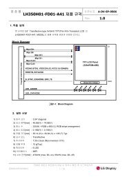
DATA SHEET<br />
TFT COLOR LCD MODULE<br />
NL3224AC35-<strong>01</strong><br />
14 cm (5.5 Type), 320 × 240 Pixels, Full <strong>color</strong><br />
NTSC/PAL mode, Incorporated backlight with inverter<br />
NL3224AC35-<strong>01</strong> is a TFT (thin film transistor) active matrix <strong>color</strong> liquid crystal display (LCD) <strong>com</strong>prising<br />
amorphous silicon TFT attached to each signal electrode, a driving circuit and a backlight. NL3224AC35-<strong>01</strong> has<br />
a built-in backlight.<br />
The 14 cm diagonal display area contains 320×240 pixels and can display full-<strong>color</strong> simultaneously.<br />
1. FEATURES<br />
Analog RGB interface<br />
Low reflection<br />
High luminance<br />
NTSC/PAL mode<br />
Reversible horizontal and vertical scanning<br />
234/240 line display<br />
Incorporated edge type backlight<br />
Designed viewing direction: 10 and 2 o'clock<br />
2. APPLICATIONS<br />
Car navigations<br />
TV monitors<br />
Video games<br />
Monitors for process controller<br />
Document No. EN<strong>01</strong>70EJ1V0DS00<br />
Date Published May 1996 M<br />
Printed in Japan<br />
©<br />
1996
NL3224AC35-<strong>01</strong><br />
3. STRUCTURE AND FUNCTIONS<br />
A TFT <strong>color</strong> LCD <strong>module</strong> <strong>com</strong>prises a TFT LCD panel, LSIs for driving liquid crystal, and a backlight. The TFT<br />
LCD panel is <strong>com</strong>posed of a TFT array glass substrate superimposed on a <strong>color</strong> filter glass substrate with liquid<br />
crystal filled in the narrow gap between two substrates. The backlight apparatus is located on the backside of the<br />
LCD panel.<br />
RGB (Red, Green, Blue) data signals are sent to LCD panel drivers after modulation into suitable forms for<br />
active matrix addressing through signal processor.<br />
Each of the liquid crystal cells acts as an electro-optical switch that controls the light transmission from the<br />
backlight by a signal applied to a signal electrode through the TFT switch.<br />
4. OUTLINE OF CHARACTERISTICS (at room temperature)<br />
Display area<br />
111.36 (H) × 83.52 (V) mm<br />
Drive system<br />
a-Si TFT active matrix<br />
Display <strong>color</strong>s<br />
Full-<strong>color</strong><br />
Number of pixels 320 × 240<br />
Pixel arrangement<br />
RGB vertical stripe<br />
Pixel pitch<br />
0.348 (H) × 0.348 (V) mm<br />
Module size<br />
134.0 (H) × 110.0 (V) × 23.0 max.(D) mm<br />
Weight<br />
315 g (typ.)<br />
Contrast ratio<br />
85:1 (typ.)<br />
Viewing angle (more than the contrast ratio of 10:1)<br />
• Horizontal: 45˚ (typ. left side, right side)<br />
• Vertical: 30˚ (typ. up side), 15˚ (typ. down side)<br />
Designed viewing direction<br />
• wider viewing angle with contrast ratio : 10 and 2 o'clock<br />
• wider viewing angle without image reversal : down side (6 o'clock)<br />
• optimum grayscale (γ =2.2)<br />
: perpendicular<br />
Color gamut<br />
50% (typ. center, to NTSC)<br />
Response time<br />
50 ms (max.), "white" to "black"<br />
Luminance<br />
250 cd/m 2 (typ.)<br />
Signal system<br />
Analog RGB signals, synchronous signals (CLK, HS, VS)<br />
Supply voltage<br />
9.5 V (LCD power supply), 9.5 V (Backlight power supply)<br />
Backlight<br />
Edge light type, one fluorescent lamp (cold cathode type)<br />
Power consumption<br />
6.6 W (typ.)<br />
2
NL3224AC35-<strong>01</strong><br />
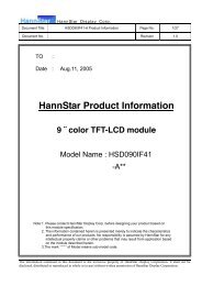
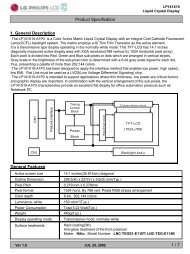
5. BLOCK DIAGRAM<br />
Video circuit board<br />
Analog RGB<br />
DC<br />
clamp<br />
Analog<br />
SW<br />
Gamma<br />
correction<br />
AMP<br />
DC<br />
shift<br />
H-Driver<br />
Clamp-pulse<br />
MUTE<br />
Video<br />
select<br />
HS<br />
VS<br />
V-Driver<br />
+<br />
Panel<br />
COM<br />
signal<br />
Controller<br />
234 / 240 select<br />
Reversible select<br />
• horizontal<br />
• vertical<br />
NTSC/PAL select<br />
Luminance control<br />
VDC<br />
ICs<br />
DC/DC<br />
converter<br />
Inverter<br />
backlight<br />
Drivers<br />
VDCB<br />
3
NL3224AC35-<strong>01</strong><br />
6. SPECIFICATION<br />
6.1 GENERAL SPECIFICATIONS<br />
Item Specifications Unit<br />
Module size 134.0± 0.5 (H) × 110.0±0.5 (V) × 23.0 max. (D) mm<br />
Display area 111.36 (H) × 83.52 (V) mm<br />
Number of dots 320 × 3 (H) × 240 (V) dot<br />
Dot pitch 0.116 (H) × 0.348 (V) mm<br />
Pixel pitch 0.348 (H) × 0.348 (V) mm<br />
Pixel arrangement RGB (Red, Green, Blue) vertical stripe –<br />
Display <strong>color</strong>s Full-<strong>color</strong> <strong>color</strong><br />
Weight 330 (max.) g<br />
note : An inverter is incorporated with the <strong>module</strong>.<br />
6.2 ABSOLUTE MAXIMUM RATINGS<br />
Parameter Symbol Ratings Unit Remarks<br />
Supply voltage<br />
VDC –0.5 to 20.0 V<br />
VDCB –0.5 to 20.0 V<br />
Ta=25˚C<br />
Analog RGB VIN1 –2.5 to 2.5 V<br />
input signal<br />
Logic input voltage VIN2 –0.5 to 5.5 V<br />
Ta=25˚C<br />
VDC=9.5 V<br />
Storage temp. TST –40 to 95 ˚ C ––<br />
Operating temp. TOP –30 to 85 ˚ C Module surface ∗<br />
95% relative humidity Ta=40˚C<br />
Humidity<br />
∗ measured at the center of the display area<br />
85% relative humidity Ta=50˚C<br />
Absolute humidity shall not exceed<br />
Ta>50˚C<br />
Ta=50˚C, 85% relative humidity level.<br />
no<br />
condensation<br />
6.3 ELECTRICAL CHARACTERISTICS<br />
(1) Power supply, logic input<br />
Ta = 25˚C<br />
Parameter Symbol min. typ. max. Unit Remarks<br />
Supply voltage<br />
VDC 8.0 9.5 13.0 V For processor,<br />
controller and driver<br />
VDCB 8.0 9.5 13.0 V For backlight<br />
Logic input "L" voltage VIL 0 – 0.9 V<br />
Logic input "H" voltage VIH 3.15 – 5.0 V<br />
Logic output "L" voltage VOL 0 – 0.3 V<br />
––<br />
Logic output "H" voltage VOH 4.5 – 5.0 V<br />
Supply current<br />
IDC – (147) 200 mA At dot-checkered pattern<br />
(VDC = 9.5 V)<br />
IDCB – (541) 600 mA Maximum luminance<br />
(VDCB = 9.5 V)<br />
4
NL3224AC35-<strong>01</strong><br />
(2) Analog RGB signals<br />
Ta = 25˚C<br />
Parameter min. typ. max. Unit Remarks<br />
Analog RGB input voltage (white - black) 0 – 0.7 Vp-p<br />
DC input level (black level) –1.0 – 1.0 V<br />
Zi = 75 Ω<br />
6.4 SUPPLY VOLTAGE SEQUENCE<br />
VDC<br />
0<<br />
NL3224AC35-<strong>01</strong><br />
6.5 INTERFACE PIN CONNECTION<br />
(1) Connector (CN1)<br />
Part no. : 52610-3<strong>01</strong>7<br />
Supplier : Molex<br />
Adaptable cable : SUMI-CARD 1.0 mm pitch 30 wick 85˚C quality<br />
Supplier : SUMITOMO ELECTRIC INDUSTRIES, LTD.<br />
Pin No. Symbol Pin No. Symbol Pin No. Symbol<br />
1 GNDD 11 EXTCSL 21 GNDD<br />
2 EXTCLK 12 GNDD 22 GNDD<br />
3 GNDD 13 N/P 23 GNDD<br />
4 HS 14 MTSL 24 GNDA<br />
5 VS 15 U/D 25 R<br />
6 HOUT 16 R/L 26 GNDA<br />
7 VOUT 17 GNDD 27 G<br />
8 BPLS 18 VDCB 28 GNDA<br />
9 GNDD 19 VDCB 29 B<br />
10 GNDD 20 VDC 30 GNDA<br />
<br />
Upper side<br />
CN1<br />
1<br />
<br />
30<br />
Lower side<br />
6
NL3224AC35-<strong>01</strong><br />
6.6 PIN DESCRIPTION<br />
Symbol In/Out Logic Description<br />
R In – Analog Red signal 0.7 Vp-p Zi=75 Ω<br />
G In – Analog Green signal 0.7 Vp-p Zi=75 Ω<br />
B In – Analog Blue signal 0.7 Vp-p Zi=75 Ω<br />
EXTCLK In ∗1 Negative External clock<br />
EXTCLK be<strong>com</strong>es active, when EXTCSL is "H".<br />
HS In ∗1 Negative Horizontal synchronous signal<br />
VS In ∗1 Negative Vertical synchronous signal<br />
HOUT Out ∗1 Negative Horizontal synchronous signal output<br />
VOUT Out ∗1 Negative Vertical synchronous signal output<br />
EXTCSL In ∗1 – Clock select signal H : external clock<br />
Default value is L L : internal clock<br />
R/L In ∗1 – Horizontal scanning select signal H : Right scanning<br />
Default value is L<br />
L : Left scanning<br />
U / D In ∗1 – Vertical scanning select signal H : down scanning<br />
Default value is L<br />
L : up scanning<br />
N / P In ∗1 – Display mode select H : PAL mode<br />
Default value is L<br />
L : NTSC mode<br />
MTSL In ∗1 – Vertical display area select signal H : 240 lines<br />
Default value is L<br />
L : 234 lines<br />
BPLS In ∗1 – Luminance control signal (pulse input)<br />
Luminance is controlled by the pulse width.<br />
Duty 100%: luminance max. Refer to P13.<br />
VDC In – Power supply for processor, controller and driver (+9.5 V)<br />
VDCB In – Power supply for backlight (+9.5 V)<br />
GNDA – – Ground for analog RGB signal<br />
GNDD – – Ground for logic and backlight<br />
∗1 : CMOS level<br />
6.7 SIGNALS<br />
No. Functions Description<br />
1 Reversible horizontal scanning R/L signal is able to reverse scanning direction.<br />
(Right → Left or Left → Right)<br />
2 Reversible vertical scanning U/D signal is able to reverse scanning direction.<br />
(Up → Down or Down → Up)<br />
3 NTSC/PAL mode N/P signal is able to change operating mode.<br />
(NTSC → PAL or PAL → NTSC)<br />
Scanning line is thinned out at the rate of seven to six lines in the PAL mode.<br />
4 234/240 line display MTSL signal is able to change scanning line.<br />
(234 lines → 240 lines or 240 lines → 234 lines)<br />
7
NL3224AC35-<strong>01</strong><br />
6.8 INPUT SIGNAL TIMING<br />
(1) mode: NTSC, internal CLK<br />
Parameter Symbol min. typ. max. Unit Remarks<br />
CLK Frequency 1 / tc – 6.36 – MHz –<br />
– 157.32 – ns<br />
Rise/fall tcrf – – 70 ns –<br />
Duty tch / tc 0.4 0.5 0.6 – –<br />
HS Frequency th 60.38 63.56 66.74 µs 15.734 kHz<br />
– 404 – CLK (typ.)<br />
Display thd – 50.34 – µs –<br />
– 320 – CLK<br />
Pulse-width thp 1.0 4.7 – µs –<br />
– 30 – CLK<br />
Pulse-width – 11.<strong>01</strong> – µs 234 line<br />
+back-porch – 70 – CLK<br />
thpb – – – – – – – – – – – – – – – – – – – – – – – – – – – – – – – – – – – – – – – – – – – – –<br />
– 12.11 – µs 240 line<br />
– 77 – CLK<br />
CLK-Hsync timing<br />
hold/setup time<br />
V-Hsync timing<br />
hold/setup time<br />
thch 10.0 – – ns –<br />
thcs 10.0 – – ns –<br />
thvh 1 – – CLK –<br />
thvs 10.0 – – ns –<br />
Rise/fall thrf – – 10.0 ns –<br />
VS Frequency tv 15.85 16.68 17.51 ms 59.94 Hz<br />
– 262.5 – H (typ.)<br />
Display – 14.87 – ms 234 line<br />
– 234 – H<br />
tvd – – – – – – – – – – – – – – – – – – – – – – – – – – – – – – – – – – – – – – – – – – – – –<br />
– 15.25 – ms 240 line<br />
– 240 – H<br />
Pulse-width tvp 158.89 190.67 – µs –<br />
– 3 – H<br />
Pulse-width tvpb – 1.33 – ms –<br />
+back-porch – 21 – H<br />
Rise/fall tvrf – – 10.0 ns –<br />
note 1 : In the display start period (pulse-width + back-porch), analog RGB signals should be blanking level.<br />
8
NL3224AC35-<strong>01</strong><br />
(2) mode: PAL, internal CLK<br />
Parameter Symbol min. typ. max. Unit Remarks<br />
CLK Frequency 1 / tc – 6.45 – MHz –<br />
– 154.96 – ns<br />
Rise/fall tcrf – – 70 ns –<br />
Duty tch / tc 0.4 0.5 0.6 – –<br />
HS Frequency th 60.80 64.00 67.20 µs 15.625 kHz<br />
– 413 – CLK (typ.)<br />
Display thd – 49.60 – µs –<br />
– 320 – CLK<br />
Pulse-width thp 1.0 4.7 – µs –<br />
– 30 – CLK<br />
Pulse-width – 11.93 – µs 234 line<br />
+back-porch – 77 – CLK<br />
thpb – – – – – – – – – – – – – – – – – – – – – – – – – – – – – – – – – – – – – – – – – – – – –<br />
– 12.71 – µs 240 line<br />
– 82 – CLK<br />
CLK-Hsync timing<br />
hold/setup time<br />
V-Hsync timing<br />
hold/setup time<br />
thch 10.0 – – ns –<br />
thcs 10.0 – – ns –<br />
thvh 1 – – CLK –<br />
thvs 10.0 – – ns –<br />
Rise/fall thrf – – 10.0 ns –<br />
VS Frequency tv 19.00 20.00 21.00 ms 50.00 Hz<br />
– 312.5 – H (typ.)<br />
Display – 17.47 – ms 234 line<br />
– 273 – H<br />
tvd – – – – – – – – – – – – – – – – – – – – – – – – – – – – – – – – – – – – – – – – – – – – –<br />
– 17.92 – ms 240 line<br />
– 280 – H<br />
Pulse-width tvp 153.60 192.00 – µs –<br />
– 2.5 – H<br />
Pulse-width<br />
+back-porch<br />
tvpb<br />
– 1.86 – ms 234 line<br />
– 29 – H<br />
– – – – – – – – – – – – – – – – – – – – – – – – – – – – – – – – – – – – – – – – – – – – –<br />
– 1.66 – ms 240 line<br />
– 26 – H<br />
Rise/fall tvrf – – 10.0 ns –<br />
note 1 : In the display start period (pulse-width + back-porch), analog RGB signals should be blanking level.<br />
9
NL3224AC35-<strong>01</strong><br />
(3) mode : NTSC, external CLK<br />
Parameter Symbol min. typ. max. Unit Remarks<br />
EXTCLK Frequency 1 / tc – 8.0 – MHz –<br />
118.75 125.00 131.25 ns<br />
Rise/fall tcrf – – 10 ns –<br />
Duty tch / tc 0.4 0.5 0.6 – –<br />
HS Frequency th 60.38 63.56 66.74 µs 15.734 kHz<br />
– 508 – CLK (typ.)<br />
Display thd – 40.00 – µs –<br />
– 320 – CLK<br />
Pulse-width thp 1.0 4.7 – µs –<br />
– 38 – CLK<br />
Pulse-width – 8.75 – µs 234 line<br />
+back-porch – 70 – CLK<br />
thpb – – – – – – – – – – – – – – – – – – – – – – – – – – – – – – – – – – – – – – – – – – – – –<br />
– 9.63 – µs 240 line<br />
– 77 – CLK<br />
CLK-Hsync timing<br />
hold/setup time<br />
V-Hsync timing<br />
hold/setup time<br />
thch 10.0 – – ns –<br />
thcs 10.0 – – ns –<br />
thvh 1 – – CLK –<br />
thvs 10.0 – – ns –<br />
Rise/fall thrf – – 10.0 ns –<br />
VS Frequency tv 15.85 16.68 17.51 ms 59.94 Hz<br />
– 262.5 – H (typ.)<br />
Display – 14.87 – ms 234 line<br />
– 234 – H<br />
tvd – – – – – – – – – – – – – – – – – – – – – – – – – – – – – – – – – – – – – – – – – – – – –<br />
– 15.25 – ms 240 line<br />
– 240 – H<br />
Pulse-width tvp 158.89 190.67 – µs –<br />
– 3 – H<br />
Pulse-width tvpb – 1.33 – ms –<br />
+back-porch – 21 – H<br />
Rise/fall tvrf – – 10.0 ns –<br />
Analog<br />
R, G, B<br />
Setup time tdas 10.0 – – ns –<br />
Hold time tdah 10.0 – – ns –<br />
note 1 : In the display start period (pulse-width + back-porch), analog RGB signals should be blanking level.<br />
10
NL3224AC35-<strong>01</strong><br />
(4) mode : PAL, external CLK<br />
Parameter Symbol min. typ. max. Unit Remarks<br />
EXTCLK Frequency 1 / tc – 8.0 – MHz –<br />
118.75 125.00 131.25 ns<br />
Rise/fall tcrf – – 10 ns –<br />
Duty tch / tc 0.4 0.5 0.6 – –<br />
HS Frequency th 60.80 64.00 67.20 µs 15.625 kHz<br />
– 512 – CLK (typ.)<br />
Display thd – 40.00 – µs –<br />
– 320 – CLK<br />
Pulse-width thp 1.0 4.7 – µs –<br />
– 38 – CLK<br />
Pulse-width – 9.63 – µs 234 line<br />
+back-porch – 77 – CLK<br />
thpb – – – – – – – – – – – – – – – – – – – – – – – – – – – – – – – – – – – – – – – – – – – – –<br />
– 10.25 – µs 240 line<br />
– 82 – CLK<br />
CLK-Hsync timing<br />
hold/setup time<br />
V-Hsync timing<br />
hold/setup time<br />
thch 10.0 – – ns –<br />
thcs 10.0 – – ns –<br />
thvh 1 – – CLK –<br />
thvs 10.0 – – ns –<br />
Rise/fall thrf – – 10.0 ns –<br />
VS Frequency tv 19.00 20.00 21.00 ms 50.00 Hz<br />
– 312.5 – H (typ.)<br />
Display – 17.47 – ms 234 line<br />
– 273 – H<br />
tvd – – – – – – – – – – – – – – – – – – – – – – – – – – – – – – – – – – – – – – – – – – – – –<br />
– 17.92 – ms 240 line<br />
– 280 – H<br />
Pulse-width tvp 153.60 192.00 – µs –<br />
– 2.5 – H<br />
Pulse-width<br />
+back-porch<br />
tvpb<br />
– 1.86 – ms 234 line<br />
– 29 – H<br />
– – – – – – – – – – – – – – – – – – – – – – – – – – – – – – – – – – – – – – – – – – – – –<br />
– 1.66 – ms 240 line<br />
– 26 – H<br />
Rise/fall tvrf – – 10.0 ns –<br />
Analog<br />
R, G, B<br />
Setup time tdas 10.0 – – ns –<br />
Hold time tdah 10.0 – – ns –<br />
note 1 : In the display start period (pulse-width + back-porch), analog RGB signals should be blanking level.<br />
11
NL3224AC35-<strong>01</strong><br />
6.9 DEFINITION OF INPUT SIGNAL TIMING<br />
tc<br />
tch<br />
CLK<br />
VIH ∗<br />
1.5 V<br />
VIL ∗<br />
tcrf<br />
tdas<br />
tdah<br />
R<br />
G<br />
B<br />
thch<br />
thcs<br />
HS<br />
VIH ∗<br />
1.5 V<br />
VIL ∗<br />
thrf<br />
VS<br />
VIH ∗<br />
1.5 V<br />
VIL ∗<br />
tvrf<br />
thvh<br />
thvs<br />
HS<br />
VIH ∗<br />
1.5 V<br />
VIL ∗<br />
VIH ∗<br />
1.5 V<br />
VIL ∗<br />
12<br />
∗ V IH = 3.15 V (min.) to 5.00 V (max.)<br />
V IL = 0.00 V (min.) to 0.90 V (max.)
NL3224AC35-<strong>01</strong><br />
<br />
tv<br />
tvp<br />
VS<br />
tvb<br />
Display period<br />
tvpb<br />
tvd<br />
<br />
th<br />
thp<br />
HS<br />
thb<br />
Display period<br />
thpb<br />
thd<br />
<br />
BPLS<br />
A<br />
B<br />
Pulse A duty 100%: Relative luminance 100%<br />
Pulse A duty 20%: Relative luminance 10%(reference value)<br />
A : 800 µ s to 3.7 ms<br />
B : 3.7 ms±10%<br />
13
NL3224AC35-<strong>01</strong><br />
7. GENERAL CAUTION<br />
WARNING<br />
Do not remove the rear case while the LCD <strong>module</strong> is operating, because dangerous high voltage is<br />
generating.<br />
(1) Caution when taking out the <strong>module</strong><br />
q Pick the pouch only, when taking out <strong>module</strong> from a shipping package.<br />
(2) Cautions for handling the <strong>module</strong><br />
q As the electrostatic discharges may break the LCD <strong>module</strong>, handle the LCD <strong>module</strong> with care. Peel a<br />
protection sheet off from the LCD panel surface as slowly as possible.<br />
w As the LCD panel and back-light element are made from fragile glass material, impulse and pressure to<br />
the LCD <strong>module</strong> should be avoided.<br />
e As the surface of polarizer is very soft and easily scratched, use a soft dry cloth without chemicals for<br />
cleaning.<br />
r Do not pull the interface connectors in or out while the LCD <strong>module</strong> is operating.<br />
t Put the <strong>module</strong> display side down on a flat horizontal plane.<br />
y Handle connectors and cables with care.<br />
(3) Cautions for the operation<br />
q When the <strong>module</strong> is operating,do not lose CLK, HS, or VS signals. If any one of these signals is lost, the<br />
LCD panel would be damaged.<br />
w Obey the supply voltage sequence. If wrong sequence is applied, the <strong>module</strong> would be damaged.<br />
e Should not intermittently operate the <strong>module</strong>. It will be the cause of a short life.<br />
(4) Cautions for the atmosphere<br />
q Dew drop atmosphere should be avoided.<br />
w Do not store and/or operate the LCD <strong>module</strong> in a high temperature and/or humidity atmosphere. Storage<br />
in an electro-conductive polymer packing pouch and under relatively low temperature atmosphere is<br />
re<strong>com</strong>mended.<br />
e Backlight lamp tend to increase the turn on voltage in a cold atmosphere. And the life of <strong>module</strong> will<br />
be<strong>com</strong>e short.<br />
(5) Cautions for the <strong>module</strong> characteristics<br />
q Do not apply fixed pattern data signal to the LCD <strong>module</strong> at product aging. Applying fixed pattern for<br />
a long time may cause image sticking.<br />
(6) Other cautions<br />
q Do not disassemble and/or re-assemble LCD <strong>module</strong>.<br />
w Do not re-adjust variable resistor or switch etc.<br />
e When returning the <strong>module</strong> for repair or etc., Please pack the <strong>module</strong> not to be broken. We re<strong>com</strong>mend<br />
to use the original shipping packages.<br />
Liquid Crystal Display has the following specific characteristics. There are not defects or malfunctions.<br />
The display condition of LCD <strong>module</strong> may be affected by the ambient temperature.<br />
The LCD <strong>module</strong> uses cold cathode tubes for backlighting. Optical characteristics, like luminance or<br />
uniformity, will change during time.<br />
Uneven brightness and/or small spots may be noticed depending on different display patterns.<br />
14
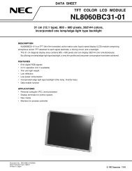
NL3224AC35-<strong>01</strong><br />
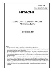
OUTLINE DRAWING (Unit in mm) Front view<br />
NL3224AC35–<strong>01</strong><br />
134.0±0.5<br />
(118.0)<br />
Module center<br />
Active area center<br />
(2.25)<br />
(Active area : 111.36)<br />
Name plate<br />
23 MAX.<br />
(Active area : 83.52)<br />
(89.5)<br />
110.0±0.5<br />
15
NL3224AC35-<strong>01</strong><br />
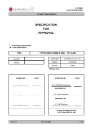
OUTLINE DRAWING (Unit in mm) Rear view<br />
86.0±0.1<br />
High voltage caution label<br />
4-M3.0<br />
(54.4)<br />
Mounting holes<br />
Depth 4 mm<br />
111.0±0.1<br />
Disposal method label<br />
Bar code label<br />
1 30<br />
(13)<br />
86.0±0.1<br />
16
NL3224AC35-<strong>01</strong><br />
17
18<br />
NL3224AC35-<strong>01</strong>
NL3224AC35-<strong>01</strong><br />
19
NL3224AC35-<strong>01</strong><br />
No part of this document may be copied in any form or by any means without the prior written consent of<br />
NEC Corporation.<br />
NEC Corporation does not assume any liability for infringement of patents, copyrights or other intellectual<br />
property rights of third parties by or arising from use of a device described herein or any other liability arising<br />
from use of such device. No license, either express, implied or otherwise, is granted under any patents, copyrights<br />
or other intellectual property rights of NEC Corporation or others.