Instruction Sheet Swing Cylinders -- Imperial - Enerpac
Instruction Sheet Swing Cylinders -- Imperial - Enerpac
Instruction Sheet Swing Cylinders -- Imperial - Enerpac

You also want an ePaper? Increase the reach of your titles
YUMPU automatically turns print PDFs into web optimized ePapers that Google loves.
®<br />
PRODUCTION AUTOMATION<br />
L1717 Rev. A 09/95<br />
IMPORTANT RECEIVING INSTRUCTIONS<br />
Visually inspect all components for shipping damage. If any shipping damage is<br />
found, notify carrier at once. Shipping damage is NOT covered by warranty. The<br />
carrier is responsible for all repair or replacement cost resulting from damage in<br />
shipment.<br />
INSIDE THIS INSTRUCTION SHEET<br />
DESCRIPTION.....................................................1<br />
SPECIFICATIONS ...............................................2<br />
PRELIMANARY INFORMATION ....................3<br />
MOUNTING SPECIFICATIONS........................4<br />
Mounting Threaded Body <strong>Cylinders</strong>..................4<br />
Mounting Upper and Lower Flange <strong>Cylinders</strong> ..5<br />
INSTALLATION..................................................6<br />
Changing Plunger Rotation ................................6<br />
Attaching Clamp Arm ........................................7<br />
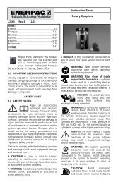
DESCRIPTION<br />
<strong>Instruction</strong> <strong>Sheet</strong><br />
<strong>Swing</strong> <strong>Cylinders</strong> -- <strong>Imperial</strong><br />
Arms for Upper Flange Body ............................ 7<br />
Hydraulic Connections....................................... 8<br />
Port Identification............................................... 8<br />
OPERATION...................................................... 16<br />
Vent Plug.......................................................... 16<br />
Pressure and Flow Rate.................................... 16<br />
MAINTENANCE............................................... 10<br />
TROUBLESHOOTING ..................................... 10<br />
CLAMP ARM MACHINING SPEC.’S ............ 11<br />
These swing cylinders are designed to swing 90° in a clockwise or<br />
counter-clockwise direction. They can also be used in straight clamping<br />
applications. Single-acting and double-acting swing cylinders are available.<br />
Clamp arms are not supplied with cylinders. Clamp arms can be purchased<br />
separately or made according to the specifications on page 11.<br />
Model Number Code<br />
1 2 3 4 optional 5 6 optional<br />
S = swing T = threaded body R = right swing S = single- L = long 1 = 1,3 kN 1 = imperial V = Viton<br />
cylinder U = upper flange L = left swing acting stroke 2 = 2,2 kN<br />
L = lower flange S = straight<br />
(no swing)<br />
D = doubleacting<br />
12 kN only<br />
5 = 5,6 kN<br />
12 = 11,6 kN
SPECIFICATIONS<br />
Arm Length [inches (mm)] straight pull<br />
Operating Specifications — Maximum Flow Rate Chart<br />
Also see graphs on page 3.<br />
300 lb (1,3 kN) — Maximum Clamp Arm Length is 2.25" (57 mm)<br />
0.87 (20)<br />
standard arm<br />
1.25 (32)<br />
extended<br />
1.75 (44)<br />
extended<br />
2.25 (57)<br />
extended —<br />
Max. Flow [in 3 /min (cc/min)] 10 (164) 10 (164) 5 (83) 5 (83) 5 (83) —<br />
Max. Pressure [psi (bar)] 5000 (350) 5000 (350) 2500 (172) 2000 (138) 1100 (76) —<br />
Clamping Force [lbs (kN)] 347 (1,5) 300 (1,3) 150 (0,67) 100 (0,44) 50 (0,22) —<br />
Arm Length [inches (mm)] straight pull<br />
500 lb (2,2 kN) — Maximum Clamp Arm Length is 3" (76 mm)<br />
0.97 (25)<br />
standard arm<br />
1.5 (38)<br />
extended<br />
2.0 (51)<br />
extended<br />
2.5 (64)<br />
extended<br />
3.0 (76)<br />
extended<br />
Max. Flow [in 3 /min (cc/min)] 12 (197) 12 (197) 6 (98) 6 (98) 6 (98) 6 (98)<br />
Max. Pressure [psi (bar)] 5000 (350) 5000 (350) 3000 (207) 2100 (145 1850 (128) 1550 (107)<br />
Clamping Force [lbs (kN)] 585 (2,6) 500 (2,2) 275 (1,2) 175 (0,8) 150 (0,7) 110 (0,5)<br />
Arm Length [inches (mm)] straight pull<br />
1250 lb (5,6 kN) — Maximum Clamp Arm Length is 5" (127 mm)<br />
1.58 (40)<br />
standard arm<br />
2.0 (51)<br />
extended<br />
3.0 (76)<br />
extended<br />
4.0 (102)<br />
extended<br />
5.0 (127)<br />
extended<br />
Max. Flow [in 3 /min (cc/min)] 25 (410) 25 (410) 12 (197) 12 (197) 12 (197) 12 (197)<br />
Max. Pressure [psi (bar)] 5000 (350) 5000 (350) 3800 (262) 2500 (172) 1900 (131) 1500 (103)<br />
Clamping Force [lbs (kN)] 1390 (6,2) 1100 (5,0) 750 (3,3) 450 (2,0) 275 (1,2) 200 (0,9)<br />
Arm Length [inches (mm)] straight pull<br />
Cylinder Specifications<br />
Capacity [lbs (kN)] 300 (1,3) 500 (2,2) 1250 (5,6) 2600 (11,6) 2600 (11,6)<br />
Long Stroke<br />
Body Style threaded body, lower flange , or upper flange mounting upper flange<br />
mounting<br />
Cylinder Type double-acting single-acting and double-acting double-acting<br />
Hydraulic<br />
Stroke [in (mm)]<br />
Effective Area<br />
[in 2 (cm 2 )]<br />
Oil Capacity<br />
[in 3 (cm 3 )]<br />
clamp 0.26 (6,6) 0.32 (8,1) 0.39 (9,9) 0.50 (12,7) 1.25 (31,8)<br />
total 0.51 (13,0) 0.65 (16,5) 0.89 (22,6) 1.12 (28,4) 1.87 (47,5)<br />
clamp 0.07 (0,45) 0.19 (1,22) 0.28 (1,81) 0.63 (4,06) 0.63 (16,0)<br />
unclamp 0.15 (0,97) 0.24 (1,55) 0.59 (3,81) 1.23 (7,94) 1.23 (31,2)<br />
clamp 0.04 (0,66) 0.28 (4,59) 0.63 (10,3) 0.71 (11,6) 1.18 (30,0)<br />
unclamp 0.08 (1,31) 0.59 (9,67) 1.23 (20,2) 1.38 (22,6) 2.30 (58,4)<br />
2600 (11,6 kN) — Maximum Clamp Arm Length is 6" (152 mm) includes long stroke version<br />
2.00 (51)<br />
standard arm<br />
3.00 (76)<br />
extended<br />
4.00 (102)<br />
extended<br />
5.00 (127)<br />
extended<br />
6.00 (152)<br />
extended<br />
Max. Flow [in 3 /min (cc/min)] 100 (1639) 100 (1639) 50 (820) 50 (820) 50 (820) 50 (820)<br />
Max. Pressure [psi (bar)] 5000 (350) 5000 (350) 3400 (235) 2600 (179) 2000 (138) 1700 (117)<br />
Clamping Force [lbs (kN)] 3100 (13,8) 2600 (11,6) 1600 (7,1) 1100 (4,9) 750 (3,3) 600 (2,7)<br />
2
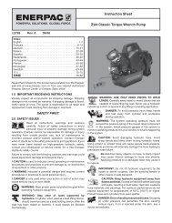
Clamping Force -v- Arm Length Graphs<br />
Clamping Force (lbs. [kN])<br />
Clamping Force (lbs. [kN])<br />
400 [1,78]<br />
100 [0,45]<br />
0<br />
300 [1,34] 1<br />
200 [0,89]<br />
0<br />
1500 [6,67]<br />
0<br />
1200 [5,34]<br />
900 [4,00]<br />
600 [2,67]<br />
300 [1,33]<br />
0<br />
300 lb (1,3 kN) Models<br />
.50 1.00 1.50<br />
[13] [25] [38]<br />
Arm Length (in. [mm])<br />
1250 lb (5,6 kN) Models<br />
1.00<br />
[25]<br />
1<br />
2<br />
2.00<br />
[51]<br />
3.00<br />
[76]<br />
4.00<br />
[102]<br />
5.00<br />
[127]<br />
PRELIMINARY INFORMATION<br />
2<br />
3<br />
3<br />
2.00<br />
[51]<br />
4<br />
Arm Length (in. [mm])<br />
4<br />
5<br />
5000 [350]<br />
5000 [350]<br />
2500 [172]<br />
2000 [138]<br />
1100 [76]<br />
5000 [350]<br />
5000 [350]<br />
3800 [262]<br />
2500 [172]<br />
1900 [131]<br />
1500 [103]<br />
Max. Clamp Pressure (psi [bar])<br />
Max. Clamp Pressure (psi [bar])<br />
Clamping Force (lbs. [kN])<br />
Clamping Force (lbs. [kN])<br />
600 [2,67] 0<br />
450 [2,00]<br />
300 [1,34]<br />
150 [0,67]<br />
3500 [15,55]<br />
3000 [13,33] 0<br />
2500 [11,11]<br />
2000 [8,89]<br />
1500 [6,66]<br />
1000 [4,44]<br />
500 [3,3]<br />
0<br />
2600 lb (11,6 kN) Models<br />
0 1.00 2.00 3.00 4.00 5.00<br />
[25,4] [50,8] [76,2] [101,6] [127,0]<br />
Arm Length (in. [mm])<br />
6.00<br />
[152,4]<br />
IMPORTANT: Failure to read and follow these instructions may lead to<br />
system malfunction or product failure, and could invalidate your<br />
warranty.<br />
(1) High flow rates can lead to excessive cylinder speed which can cause cylinder<br />
damage. Hydraulic pressure and cylinder speed must be adjusted to match the<br />
length of clamp arm. The clamping force also varies with the length of the clamp<br />
arm. Refer to page 2 for operating specifications.<br />
(2) Flow controls with return checks should be used to reduce swing cylinder speed to<br />
the recommended rate. The return checks help minimize back pressure that could<br />
lead to an unclamp malfunction on single-acting systems.<br />
(3) When using single-acting swing cylinders, limit the return flow back pressure to 50<br />
psi maximum. Large diameter tubing (3/8" O.D. or larger) and flow controls with free<br />
flow return checks help minimize back pressure. Consult <strong>Enerpac</strong> for proper<br />
system design.<br />
(4) Excessive return flow back pressure can also damage double-acting swing<br />
cylinders. Limit the return flow back pressure to 600 psi maximum. Double-acting<br />
systems should be set up for a metered-in with reverse free flow in the clamp port.<br />
(5) Clamping of the part should occur at the midpoint of the vertical travel. No clamping<br />
of part shall occur while the swing clamp is turning. Clamp arm should freely travel<br />
during the 90° rotation (avoid contact with cutter heads, tools, etc.).<br />
(6) Attaching clamp arm to cylinder plunger must be done according to the instructions<br />
on page 7.<br />
3<br />
.50<br />
[13]<br />
500 lb (2,2 kN) Models<br />
1<br />
1.00 1.50 2.00<br />
[25] [38] [51]<br />
Arm Length (in. [mm])<br />
1<br />
2<br />
2<br />
3<br />
3<br />
4<br />
2.50<br />
[64]<br />
4<br />
5<br />
3.00<br />
[76]<br />
5000 [350]<br />
5000 [350]<br />
3000 [207]<br />
2100 [145]<br />
1850 [128]<br />
1550 [107]<br />
5<br />
Max. Clamp Pressure (psi [bar])<br />
5000 [350]<br />
5000 [350]<br />
3400 [235]<br />
2600 [179]<br />
2000 [138]<br />
1700 [117]<br />
Max. Clamp Pressure (psi [bar])
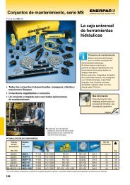
MOUNTING SPECIFICATIONS<br />
Mounting Threaded Body <strong>Cylinders</strong><br />
Threaded body cylinders can be threaded into a tapped hole, secured to the fixture<br />
using a mounting flange, threaded into the fixture and secured with a jam nut, or<br />
mounted through a clearance hole and secured with jam nuts. See illustrations<br />
below.<br />
threaded into<br />
fixture<br />
oil connection<br />
jam nut<br />
mounting<br />
flange<br />
oil connection<br />
jam nuts<br />
When a threaded body style swing cylinder is being installed in a fixture, the thread<br />
engagement should be no less than the thread engagement for the standard <strong>Enerpac</strong><br />
mounting flange. If a cylinder is being mounted using just the lower portion of the<br />
threads, the engagement should be increased for additional support. See table below<br />
for minimum thread engagement.<br />
Cylinder Capacity Minimum Thread Engagement<br />
300 lb 1,3 kN .50" 13 mm<br />
500 lb 2,2 kN .50" 13 mm<br />
1250 lb 5,6 kN .50" 13 mm<br />
2600 lb 11,6 kN .63" 16 mm<br />
4
Mounting Upper and Lower Flange <strong>Cylinders</strong><br />
A WARNING<br />
The fixture must be capable of withstanding 5,000 psi (350 bar) hydraulic<br />
working pressure when the cylinders are manifold mounted.<br />
Manifold<br />
O-ring<br />
Cylinder<br />
Capacity<br />
300 lb<br />
1kN<br />
500 lb<br />
2,2 kN<br />
1250 lb<br />
5,6 kN<br />
2600 lb<br />
11,6 kN<br />
incl.<br />
long stroke<br />
A<br />
B<br />
Max. Oil<br />
Channel<br />
Diameter<br />
Ø A<br />
0.156"<br />
4 mm<br />
0.156"<br />
4mm<br />
0.156"<br />
4 mm<br />
0.156"<br />
4 mm<br />
Before a swing cylinder can be manifold<br />
mounted, the port screw plugs and copper<br />
gaskets must be removed.<br />
The o-rings provided should be<br />
lubricated and installed in the<br />
counter-bore around the port prior to<br />
mounting and bolting down the swing<br />
cylinder.<br />
Be sure that the o-ring does not get<br />
pinched or damaged during mounting as<br />
leakage could result. To prevent leakage<br />
from the manifold mounting, provide a<br />
fixture mounting surface with flatness<br />
within 0.003 in (0,08 mm) and a surface<br />
roughness not to exceed 32√ rms.<br />
C<br />
D<br />
Fixture<br />
Hole<br />
Diameter<br />
Ø B<br />
0.003<br />
Manifold<br />
O-ring<br />
Manifold Specifications<br />
Mounting<br />
Threads<br />
C<br />
Minimum<br />
Thread<br />
Depth<br />
D<br />
1.05 ± .03 8-36 UNF 0.50"<br />
13 mm<br />
1.15 ± .03 10-32 UNF 0.63"<br />
16 mm<br />
1.42 ± .03 25-28 UNF 0.75"<br />
19 mm<br />
1.93 ± .03 .3125-24<br />
UNF<br />
5<br />
0.88"<br />
22 mm<br />
Remove port<br />
screw plug.<br />
Remove port<br />
screw plug.<br />
A C<br />
Lubricated<br />
Mounting<br />
Bolt Torque<br />
29-35 in-lbs<br />
3,3-4,0 Nm<br />
40-48 in-lbs<br />
4,5-5,4 Nm<br />
9-11 ft-lbs<br />
12,2-14,9 Nm<br />
18-22 ft-lbs<br />
24,4-29,8 Nm<br />
Upper Flange<br />
o-ring<br />
o-ring<br />
D<br />
0.003<br />
Manifold<br />
O-Ring<br />
Dimensions<br />
I.D. x w<br />
0.239 x 0.070<br />
6,07 x 1,78 mm<br />
0.239 x 0.070"<br />
6,07 x 1,78 mm<br />
0.301 x 0.070"<br />
7,65 x 1,78 mm<br />
.301 x .070<br />
7,65 x 1,78 mm<br />
Lower<br />
Flange
INSTALLATION<br />
These <strong>Swing</strong> <strong>Cylinders</strong> are designed so that you can set the position of the clamp<br />
arm after mounting the cylinder. If you need to change the rotation direction, do it<br />
before mounting the cylinder.<br />
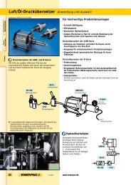
Changing Plunger Rotation (if needed)<br />
STRAIGHT<br />
Clamp Port Unclamp Port<br />
A<br />
R<br />
L<br />
S<br />
B<br />
Clamp and<br />
Unclamp Position<br />
.25"<br />
(6,4mm)<br />
Plunger<br />
Unclamp<br />
Position<br />
Retaining ring<br />
removed<br />
from groove.<br />
Clamp<br />
Arm<br />
Bolt<br />
LEFT SWING<br />
Clamp Port Unclamp Port<br />
A<br />
Clamping<br />
Arm<br />
B<br />
Clamp Position<br />
RIGHT SWING<br />
Clamp Port Unclamp Port<br />
Change plunger rotation by lining up the letter on top of the plunger with the arrow<br />
on the side of the cylinder opposite the ports. To change rotation, refer to<br />
illustrations and follow procedure below. You will need a spanner wrench.<br />
1. Position the arm on the plunger to provide a handle to grasp for moving the<br />
plunger.<br />
(a) Release the clamp arm bolt.<br />
(b) Remove the retaining ring and slide the clamp arm down the plunger until<br />
the top of the arm is 0.25" (6 mm) from the top surface of the plunger.<br />
(c) Tighten the clamp arm bolt. DO NOT discard the retaining ring.<br />
2. Place spanner wrench on bottom cylinder plug and turn the plug (facing you)<br />
counter-clockwise 4 turns.<br />
NOTE: Single-acting cylinders may need the bottom plug to be rotated more<br />
than 4 turns to help relieve return spring tension.<br />
3. Push down on the plunger and rotate it to line up the desired letter (L, R, S) with<br />
the arrow on the side of the cylinder.<br />
4. Once the letter and arrow are lined up, pull the plunger up, turn the bottom plug<br />
back in (clockwise) 4 turns, and tighten firmly.<br />
6<br />
S<br />
R<br />
L<br />
Approx.<br />
4 turns out.<br />
A<br />
L<br />
S<br />
R<br />
B<br />
Clamp Position<br />
Unclamp<br />
Position<br />
Bottom plug
Attaching Clamp Arm<br />
1. Remove the retaining ring from the top of the plunger.<br />
2. Slide the clamp arm down<br />
over the plunger and use a<br />
pliers to push the retaining<br />
ring back onto the plunger<br />
groove. Orient the<br />
retaining ring so the<br />
retaining ring gap will face<br />
the back of the clamp arm.<br />
See illustration.<br />
3. Move the clamp arm up until it is firmly against the retaining ring and in the<br />
desired position. While maintaining this position, torque the clamp arm bolt to<br />
specification listed below.<br />
A CAUTION<br />
Inadequate torquing of the clamp arm bolt could cause the arm to slip<br />
during operation. BE SURE TO USE QUALITY GRADE 8 (8.8 DIN 912)<br />
SOCKET HEAD CAP SCREWS (supplied with standard clamp arms).<br />
Clamp Arm Bolt Torque<br />
Cylinder Capacity Lubricated Torque<br />
300 lbs (1,3 kN) 53-64 in-lbs (6,0-7,2 Nm)<br />
500 lbs (2,2 kN) 12 to 15 ft-lbs (16,3 to 20,3 Nm)<br />
1250 lbs (5,6 kN) 24 to 29 ft-lbs (32,5 to 39,3 Nm)<br />
2600 lbs (11,6 kN) 44-53 ft-lbs (59,7-71,8 Nm)<br />
Arms for Upper Flange Body Style<br />
To use the upper flange body style cylinders,<br />
you have to be sure that the contact bolt will<br />
clear the upper flange during operation. The<br />
clamp arm must be long enough for the contact<br />
bolt to clear the upper flange as the arm swings<br />
down. Clearance problems are most common<br />
when the final clamping position is at the side of<br />
the cylinder and the contact bolt must pass by<br />
the front or back of the upper flange as it swings<br />
down. You may need to use the longer, CAL<br />
Series clamp arm for these applications.<br />
Contact<br />
Bolt<br />
Max.<br />
Length<br />
Maximum Contact Bolt Length<br />
Cylinder Capacity Maximum Length<br />
300 lbs (1,3 kN) 0.55" (14,0 mm)<br />
500 lbs (2,2 kN) 0.75" (19,1 mm)<br />
NOTE: Maximum lengths provided here are for 300 and 500 lb. upper flange models only.<br />
7
INSTALLATION (continued)<br />
Hydraulic Connections<br />
To make port connections, install fittings rated for 5000 psi (350 bar).<br />
DO NOT use thread sealant. Sealing is accomplished by using an o-ring on the<br />
fitting boss. Lubricate the o-ring prior to assembly.<br />
When designing your hydraulic circuit, remember to consider the factors listed in<br />
PRELIMINARY INFORMATION on page 3 of this <strong>Instruction</strong> <strong>Sheet</strong>. For more<br />
information about plumbing hydraulic circuits, see your <strong>Enerpac</strong> Production<br />
Automation Catalog.<br />
Port Identification<br />
A<br />
Threaded Body<br />
300 lb (1 kN)<br />
A<br />
B<br />
Side View<br />
Bottom View<br />
Unclamp<br />
Clamp<br />
Threaded<br />
Body<br />
500-2600 lb<br />
(2,2-11,6 kN)<br />
B<br />
A<br />
Side View<br />
KEY<br />
A Port:<br />
Plunger rotates 90˚ and clamps<br />
B Port:<br />
double-acting—<br />
Plunger unclamps and rotates -90˚<br />
single-acting—<br />
Vent Port<br />
Do not remove vent plug<br />
except to attach tubing. (See page 9<br />
vent plug section.)<br />
Unclamp<br />
Clamp<br />
Upper<br />
Flange<br />
Bottom View Body Style<br />
(Long Stroke)<br />
B<br />
A<br />
Cylinder Ports<br />
Cylinder Capacity 5000 psi SAE Fitting Cylinder Capacity 5000 psi SAE Fitting<br />
300 lbs (1,3 kN) #2 1250 lbs (5,6 kN) #4<br />
500 lbs (2,2 kN) #2 2600 lbs (11,6 kN) #4<br />
8<br />
Unclamp<br />
Clamp<br />
Lower<br />
Flange<br />
Body Style<br />
Side View Side View<br />
Manifold<br />
Ports<br />
Bottom View Bottom View<br />
B<br />
A<br />
Unclamp<br />
Clamp<br />
Manifold<br />
Ports
OPERATION<br />
Vent Plug<br />
<strong>Swing</strong> cylinders rotate 90° during the first portion of the stroke, continuing without<br />
rotation for the final clamping stroke. The straight downward stroke is the clamping<br />
stroke of the cylinder. Clamping force must be applied only during the vertical<br />
travel, not during the swing motion.<br />
A CAUTION<br />
—If clamping force is applied during the rotation portion of the stroke,<br />
internal plunger damage will result.<br />
—To ensure maximum cylinder performance and safety; be sure all<br />
hydraulic connections, hoses, and fittings are properly sealed and fully<br />
tightened.<br />
—Be sure all items are rated to withstand system pressures. Under-rated<br />
components will not withstand higher pressure. Using under-rated<br />
components will lead to equipment damage and possible personal injury.<br />
Single-acting cylinders have a vented plug on the left side of the cylinder when you<br />
are facing the hydraulic ports. To prevent entry of chips and coolant, the vent plug<br />
must not be removed. If the vent plug is subjected to a continuous coolant flood<br />
condition, attach tubing to the port using an SAE fitting, and run the tubing to a<br />
non-contaminated area of the fixture.<br />
Pressure and Flow Rate<br />
Clamp arm length (L) determines operating pressure setting and flow rate.<br />
See Operating Specifications — Maximum Flow Rate Chart on page 2 for clamp<br />
arm length, pressure setting and flow rate. Set operating pressure and flow rate<br />
according to the limits established by the length of the clamp arm. Do not exceed<br />
the load-to-length pressure ratios. As the arm length increases, the clamping force<br />
and maximum operating pressure are reduced.<br />
A CAUTION<br />
It is very important that you use the correct pressure and flow settings.<br />
Operating outside these limits will cause damage to the swing cylinder.<br />
Damage caused by exceeding rated pressure and maximum flow is NOT<br />
COVERED BY WARRANTY.<br />
9
MAINTENANCE<br />
TROUBLESHOOTING<br />
Maintenance is required when wear or leakage is noticed. Occasionally inspect all<br />
components to detect any problem requiring service and maintenance. <strong>Enerpac</strong><br />
offers ready-to-use Repair Parts Kits. Repair Parts <strong>Sheet</strong>s are available with<br />
assembly drawing and parts list. Contact <strong>Enerpac</strong>.<br />
IMPORTANT: Consult the Repair Parts <strong>Sheet</strong> for service information as to correct<br />
assembling and disassembling. Incorrect maintenance and service such as wrong<br />
torque values may cause product malfunctions and/or personal injury.<br />
The following information is intended to be used only as an aid in determining if a<br />
problem exists. For repair service, contact your Distributor or Authorized <strong>Enerpac</strong><br />
Service Center.<br />
Problem Possible Cause Solution<br />
1. Cylinder will not<br />
clamp/unclamp.<br />
2. Cylinder advances<br />
part way.<br />
A.pump release valve open<br />
B. no oil in pump reservoir<br />
C. air in system<br />
D.couplers not fully<br />
tightened<br />
E. blocked hydraulic line<br />
F. spring broken in cylinder<br />
A.oil level in pump too low<br />
B. plunger binding<br />
3. Cylinder A.leaking connection<br />
clamps/unclamps B. restricted hydraulic line<br />
slower than normal. C. pump malfunction<br />
4. Cylinder<br />
clamps/unclamps<br />
but will not hold<br />
pressure.<br />
A.seals damaged<br />
B. leaking connection<br />
C. pump malfunction<br />
5. Cylinder leaks oil. A.seals damaged<br />
B. plunger worn or damaged<br />
6. Clamp arm does<br />
not make swing<br />
movement.<br />
A.clamp arm loose<br />
B. plunger damaged<br />
10<br />
A.close pump release valve<br />
B. fill pump reservoir<br />
C. remove air from hydraulic system<br />
D.retighten couplers<br />
E. check valves, fittings, and tubing<br />
F. replace spring<br />
A.fill pump reservoir<br />
B. replace damaged parts<br />
—refer to Repair Parts <strong>Sheet</strong><br />
A.retighten fittings, couplers,<br />
and tubing<br />
B. check valves, fittings, and tubing<br />
C. refer to pump <strong>Instruction</strong> <strong>Sheet</strong><br />
A.replace seals<br />
—refer to Repair Parts <strong>Sheet</strong><br />
B. retighten fittings, couplers,<br />
and tubing<br />
C. refer to pump <strong>Instruction</strong> <strong>Sheet</strong><br />
A.replace seals<br />
—refer to Repair Parts <strong>Sheet</strong><br />
B. replace damaged parts<br />
—refer to Repair Parts <strong>Sheet</strong><br />
A.reposition and tighten clamp arm<br />
—see Attaching Clamp Arm<br />
on page 7<br />
B. replace damaged parts<br />
—refer to Repair Parts <strong>Sheet</strong>
CLAMP ARM MACHINING SPECIFICATIONS<br />
See Pressure and Flow Rate on page 9 to correctly measure the arm length. To<br />
determine the maximum clamping force for the arm, refer to Operating<br />
Specifications — Maximum Flow Rate Chart on page 2.<br />
"B"<br />
"E"<br />
Dimensions are in inches (mm).<br />
"H"<br />
"D"<br />
"A"<br />
"W"<br />
"G"<br />
"F" 3-PLACES<br />
2,1-3,0 [.08-.12]<br />
1,1-1,5 [.04-.06]<br />
"K"<br />
"M"<br />
"L"<br />
"J"<br />
"C"<br />
"P"<br />
"Q"<br />
"R" 2-PLACES<br />
"N"<br />
0,08 [.003]<br />
A<br />
"S"<br />
55˚-60˚<br />
"T"<br />
63√ [1,6]<br />
300 lb (1,3 kN) 500 lb (2,2 kN) 1250 lb (5,6 kN) 2600 lb (11,6kN)<br />
"A" .49-.46 (12,4-11,7) .65-.62 (16,5-15,8) .77-.74 (19,5-18,8) 1.21-1.18 (30,7-30,0)<br />
"B" Max. 3.20-3.14 (81,2-79,8) 3.98-3.96 (101,0-100,6) 6.21-6.17 (157,7-156,8) 7.52-7.48 (191,0-190,0)<br />
"C" .62-.58 (15,7-14,8) .77-.74 (19,5-18,9) 1.02-.99 (25,9-25,2) 1.41-1.38 (35,8-35,1)<br />
"D" .32-.29 (8,1-7,4) .42-.39 (10,6-10,0) .47-.44 (11,9-11,3) .65-.62 (16,5-15,8)<br />
"E" .29-.31 (7,4-7,8) .36-.38 (9,2-9,6) .50-.52 (12,8-13,2) .69-.71 (17,6-18,0)<br />
"F" 1.61-1.57 (40,8-39,9) 1.96-1.92 (49,7-48,8) 2.79-2.75 (70,8-69,9) 3.58-3.55 (90,9-90,2)<br />
"G" .60-.63 (15,3-16,0) .71-.74 (18,1-18,7) .87-.90 (22,1-22,8) 1.12-1.15 (28,5-29,2)<br />
"H" .29-.31 (7,4-7,8) .34-.36 (8,7-9,1) .44-.46 (11,2-11,6) .74-.76(18,8-19,3)<br />
"J" ,29-.31 (7,4-7,8) .37-.40 (9,4-10,1) .49-.51 (12,5-12,9) .69-.71 (17,5-18,0)<br />
"K" Dia. Ø.37-.39 (9,4-9,9) Ø.40-.42 (10,2-10,6) Ø.51-.53 (13,0-13,4) Ø.62-.64 (15,8-16,2)<br />
"L" .05-.07 (1,3-1,7) .05-.07 (1,3-1,7) .05-.07 (1,3-1,7) .05-.07 (1,3-1,7)<br />
"M" Dia. Ø.220-.227 (5,59-5,76) Ø.280-.289 (7,12-7,34) Ø.342-.351 (8,69-8,91) Ø.388-.397 (9,86-10,08)<br />
"N" Thru #10-32 UNF-2B .250-28 UNF-2b<br />
.3125-24 UNF-2B<br />
.375-24 UNF-2B<br />
or M6 x 1<br />
M8 x 1,25 or M10 x 1,5<br />
"P" .16-.18 (4,1-4,5) .21-.23 (5,4-5,8) .27-.29 (6,9-7,3) .35-.37 (8,9-9,3)<br />
"Q" .36-.32 (9,1-8,2) .46-.43 (11,6-11,0) .57-.54 (14,4-13,8) .74-.71 (18,7-18,1)<br />
"R" 7°-8° 7°-8° 6°-8° 7°-9°<br />
"S" Dia. Ø.387-.389 (9,83-9,88) Ø.456-.469 (11,82-11,91) Ø.727-.731 (18,47-18,56) Ø1.002-1.006 (25,46-25,55)<br />
"T" Dia. Ø.3145--3155<br />
Ø.3932-.3942<br />
Ø.6295-.6305 Ø.8756-.8766 (22,241-22,265)<br />
(7,989-8,013)<br />
(9,998-10,012)<br />
(15,990-16,014)<br />
"U" .10-.12 (2,6-3,0) .12-.14 (3,0-3,5) .16-.18 (4,1-4,5) .27-.29 (6,9-7,3)<br />
"V" .02-.04 (0,5-1,0) .02-.04 (0,5-1,0) .02-.04 (0,5-1,0) .02-.04 (0,5-1,0)<br />
"V" 11°-13° 13°-15° 11°-13° 17°-19°<br />
11<br />
A<br />
"U"<br />
"V"<br />
40˚-50˚
Australia<br />
<strong>Enerpac</strong><br />
Block V, Unit 3<br />
Regents Park Estate<br />
391 Park Road<br />
Regents Park NSW 2143<br />
Tel: (61) (2) 743-8988<br />
Fax:8232-674-7747<br />
Belgium, Holland,<br />
and Luxemburg<br />
<strong>Enerpac</strong> B.V.<br />
P.O. Box 269, Storkstraat 25<br />
3900AG Veenendaal<br />
Holland<br />
Tel: (8385) 35911<br />
Fax: (8385) 25613 or 26645<br />
As of October 10, 1995:<br />
Tel: (0318) 535911<br />
Fax: (0318) 525613 or 526645<br />
Canada<br />
<strong>Enerpac</strong><br />
13000 West Silver Spring Drive<br />
Butler, Wisconsin 53007, USA<br />
Tel: (800) 426-4129 User<br />
Tel: (800) 426-2284 Distributor<br />
Fax: (414) 781-1049<br />
R<br />
CIS<br />
Applied Power Moscow<br />
Leninski Prospekt 95A<br />
117313 Moscow<br />
Tel: (095) 936 2005<br />
Fax: (095) 936 2005<br />
Eastern Europe and<br />
Other European<br />
Countries,<br />
Middle East,<br />
and Africa<br />
<strong>Enerpac</strong><br />
47, avenue Blanc<br />
P.O. Box 67, CH-1211<br />
Geneva 21, Switzerland<br />
Tel: (41) 22-731 94 05<br />
Telex: 412843<br />
Fax: (41) 22-731 12 15<br />
Far East<br />
<strong>Enerpac</strong><br />
47 Jalan Pemimpin<br />
#01-02 & 01-03<br />
Sin Cheong Building<br />
Singapore 2057<br />
Thomson Road P.O. Box 114<br />
Singapore 9157<br />
Tel: (65) 2581677<br />
Telex: RS24882 APOWR<br />
Fax: (65) 2582847<br />
France<br />
<strong>Enerpac</strong><br />
B.P. 200<br />
Parc d'Activitiés du Moulin<br />
de Massy<br />
91882 Massy Cedex, France<br />
Tel: (33) 1-60 13 68 68<br />
Fax: (33) 1-69 20 37 50<br />
Germany<br />
<strong>Enerpac</strong><br />
Mündelheimer Weg 51<br />
P.O. Box 300 113<br />
D-40401 Düsseldorf 30<br />
Tel: (49) (221) 41707-0<br />
Telex: 8582790<br />
Fax: (49) (211) 4170740<br />
Italy<br />
<strong>Enerpac</strong><br />
Via Canova, 4<br />
20094 Corsico<br />
Milano, Italy<br />
Tel: 39-2-4582741<br />
Fax: 39-2-48601288<br />
Hongkong<br />
<strong>Enerpac</strong><br />
Room No. 907, Workingberg<br />
Commercial Building<br />
41-47 Marble Road, North Point<br />
Tel: (852) 561-6295<br />
Fax: (852) 561-6772<br />
India<br />
<strong>Enerpac</strong><br />
Hydraulic Technology (India) Pvt<br />
Ltd<br />
203 Vardhaman Chamber<br />
Plot #84, Sector 17<br />
Vashi, New Bombay 400 705<br />
Maharashtra<br />
Tel: 91-22-7631062<br />
Fax; 91-22-7670309<br />
Japan<br />
Applied Power Japan<br />
10-17 Sasame<br />
Kita-cho, Toda-Shi<br />
Saitama 335,<br />
Japan<br />
Tel: 81-0484-22-2251<br />
(Administration)<br />
0484-21-2311 (Sales)<br />
Telex: J26275<br />
Fax: 81-0484-22-0596<br />
Latin America<br />
and Caribbean<br />
<strong>Enerpac</strong><br />
13000 West Silver Spring Drive<br />
Butler, Wisconsin 53007<br />
Tel: (414) 781-6600 ext. 263<br />
Fax: (414) 781-5561<br />
Mexico<br />
<strong>Enerpac</strong><br />
Blvd. Gral. Felipe Angeles 1604<br />
P.O. Box 362<br />
Pachuca. Hidalgo 42080<br />
Mexico<br />
Tel: (52) 771 3-3700<br />
Fax: (52) 771 3-1196 or<br />
(52) 771 8-3800<br />
South Korea<br />
<strong>Enerpac</strong><br />
163-12, Dodang-Dong<br />
Wonmi-Ku,<br />
Buchun-Shi, Kyunggi-Do<br />
Republic of Korea<br />
Tel: (82) (32) 6750836<br />
Fax: (82) (32) 6753002<br />
All <strong>Enerpac</strong> products are guaranteed against defects in workmanship<br />
and materials for as long as you own them. Under this guarantee,<br />
free repair or replacement will be made to your satisfaction.<br />
For prompt service, contact your Authorized <strong>Enerpac</strong> Service Center<br />
or call toll free:<br />
In U.S.A. 1-800-558-0530<br />
In Canada 1-800-426-2284<br />
Spain<br />
<strong>Enerpac</strong><br />
Calle de la Imprenta, 7<br />
Poligono Industrial<br />
28100 Acobendas, Madrid<br />
Spain<br />
Tel: (34) 1-6611125<br />
Fax: ( 34) 1-6614789<br />
United Kingdom<br />
<strong>Enerpac</strong><br />
Leacon Road<br />
Ashford, Kent<br />
TN23 4TU<br />
England<br />
Tel: 44-1233-639871<br />
Telex: 966 450<br />
Fax: 44-1233-643923<br />
United States<br />
<strong>Enerpac</strong><br />
13000 West Silver Spring Drive<br />
Butler, Wisconsin 53007, USA<br />
Tel: (414) 781-6600<br />
1-800-433-2766 (End User)<br />
1-800-558-0530 (Distributor)<br />
Fax: (414) 781-1049<br />
RECYCLED<br />
PAPER<br />
PRINTED IN U.S.A.