Dual 1:1 Redundant Controller - Satcom Services
Dual 1:1 Redundant Controller - Satcom Services
Dual 1:1 Redundant Controller - Satcom Services

You also want an ePaper? Increase the reach of your titles
YUMPU automatically turns print PDFs into web optimized ePapers that Google loves.
<strong>Redundant</strong> Control Panel<br />
for <strong>Dual</strong> 1:1 Systems<br />
RCPD-1100<br />
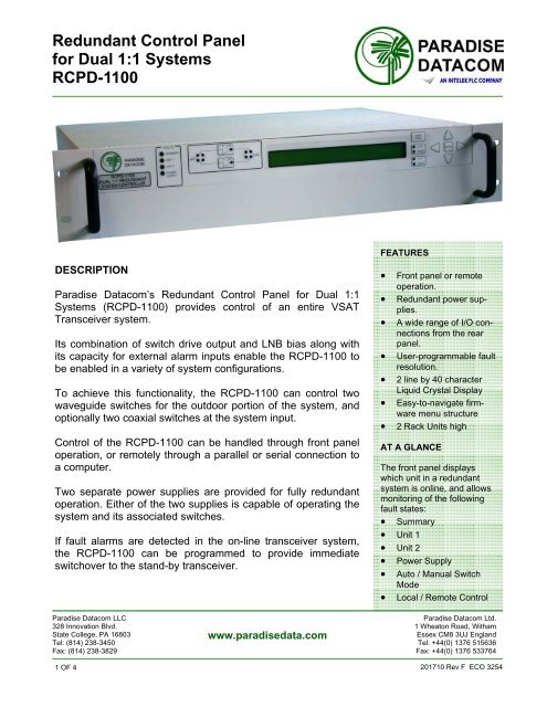
DESCRIPTION<br />
Paradise Datacom’s <strong>Redundant</strong> Control Panel for <strong>Dual</strong> 1:1<br />
Systems (RCPD-1100) provides control of an entire VSAT<br />
Transceiver system.<br />
Its combination of switch drive output and LNB bias along with<br />
its capacity for external alarm inputs enable the RCPD-1100 to<br />
be enabled in a variety of system configurations.<br />
To achieve this functionality, the RCPD-1100 can control two<br />
waveguide switches for the outdoor portion of the system, and<br />
optionally two coaxial switches at the system input.<br />
Control of the RCPD-1100 can be handled through front panel<br />
operation, or remotely through a parallel or serial connection to<br />
a computer.<br />
Two separate power supplies are provided for fully redundant<br />
operation. Either of the two supplies is capable of operating the<br />
system and its associated switches.<br />
If fault alarms are detected in the on-line transceiver system,<br />
the RCPD-1100 can be programmed to provide immediate<br />
switchover to the stand-by transceiver.<br />
FEATURES<br />
• Front panel or remote<br />
operation.<br />
• <strong>Redundant</strong> power supplies.<br />
• A wide range of I/O connections<br />
from the rear<br />
panel.<br />
• User-programmable fault<br />
resolution.<br />
• 2 line by 40 character<br />
Liquid Crystal Display<br />
• Easy-to-navigate firmware<br />
menu structure<br />
• 2 Rack Units high<br />
AT A GLANCE<br />
The front panel displays<br />
which unit in a redundant<br />
system is online, and allows<br />
monitoring of the following<br />
fault states:<br />
• Summary<br />
• Unit 1<br />
• Unit 2<br />
• Power Supply<br />
• Auto / Manual Switch<br />
Mode<br />
• Local / Remote Control<br />
Paradise Datacom LLC<br />
Paradise Datacom Ltd.<br />
328 Innovation Blvd. 1 Wheaton Road, Witham<br />
State College, PA 16803<br />
www.paradisedata.com<br />
Essex CM8 3UJ England<br />
Tel: (814) 238-3450 Tel: +44(0) 1376 515636<br />
Fax: (814) 238-3829 Fax: +44(0) 1376 533764<br />
1 OF 4<br />
201710 Rev F ECO 3254
<strong>Redundant</strong> Control Panel<br />
for <strong>Dual</strong> 1:1 Systems<br />
RCPD-1100<br />
Fault<br />
Indicators<br />
On Line Unit<br />
Selection<br />
Local/<br />
Remote Key<br />
Main Menu<br />
Key<br />
Enter<br />
Key<br />
PARADISE<br />
DATACOM<br />
RCPD-1100<br />
DUAL 1:1 REDUNDANT<br />
SYSTEM CONTROLLER<br />
System<br />
Identification<br />
Signal Path<br />
Mimic Display<br />
2 x 40<br />
LCD<br />
Auto/Manual<br />
Key<br />
Display<br />
Navigation Keys<br />
J14<br />
MODEM B RX<br />
J13<br />
MODEM A RX<br />
J15<br />
LNB A RX<br />
J16<br />
LNB B RX<br />
J10<br />
SYSTEM<br />
ALARMS OUT<br />
J11<br />
MODEM A<br />
ALARM INPUT<br />
J12<br />
MODEM B<br />
ALARM INPUT<br />
MODEL: RCPD-1100-L-01<br />
S/N: XXXX<br />
P/N: L204178-1<br />
DUAL 1:1 SYSTEM CONTROLLER<br />
J1<br />
PS1<br />
J3<br />
PLATE<br />
ASSY<br />
J4 SERIAL MAIN<br />
J5 SERIAL LOCAL<br />
J2<br />
PS2<br />
J7 PARALLEL I/O<br />
J8 EXT ALARM<br />
RCPD-1100 Front and Rear Panels<br />
J14<br />
MODEM B RX<br />
J13<br />
MODEM A RX<br />
J15<br />
LNB A RX<br />
J16<br />
LNB B RX<br />
J10<br />
SYSTEM<br />
ALARMS OUT<br />
J11<br />
MODEM A<br />
ALARM INPUT<br />
J12<br />
MODEM B<br />
ALARM INPUT<br />
MODEL: RCPD-1100-L-01<br />
S/N: XXXX P/N: L204178-1<br />
DUAL 1:1 SYSTEM CONTROLLER<br />
J1<br />
PS1<br />
J3<br />
PLATE<br />
ASSY<br />
J4 SERIAL MAIN<br />
J5 SERIAL LOCAL<br />
J2<br />
PS2<br />
J7 PARALLEL I/O<br />
J8 EXT ALARM<br />
RCPD-1100 Rear Panel, with 48VDC Option<br />
Pin Outs for J1, J2 DC Power Input<br />
Pin Function<br />
A +48 VDC<br />
B +48 VDC<br />
C -48 VDC<br />
D -48 VDC<br />
E Ground<br />
F Ground<br />
2 OF 4<br />
201710 Rev F ECO 3254
<strong>Redundant</strong> Control Panel<br />
for <strong>Dual</strong> 1:1 Systems<br />
RCPD-1100<br />
RCPD-1100 General Specifications<br />
CHARACTERISTIC SPECIFICATION<br />
Configurations RCPD-1100; <strong>Dual</strong> 1:1 <strong>Redundant</strong> System<br />
Switch Time<br />
Fault Detection, 20-50 msec<br />
Total Switchover, 100 msec maximum<br />
Switch Drive 26 VDC @ 4 amps<br />
Alarm Input<br />
Closure to Ground, (Ground=OK / Open=Fault)<br />
Serial Communications RS-232 / RS-485 4-wire<br />
Parallel I/O<br />
Status Outputs<br />
Form C Relay Contacts (10 sets)<br />
Control Inputs<br />
Contact Closure to Ground<br />
AC Input Power<br />
85-265 VAC, 47-63 Hz, 1 A max, >0.93 power factor<br />
Mechanical Dimensions 3.5 in. H x 19 in. W x 13.3 in. D [2 RU]<br />
(89 mm H x 483 mm W x 338 mm D)<br />
Weight<br />
6 lbs. (2.8 kg)<br />
Environmental temperature 0-50 o C<br />
Control Cable Connector Port (J3) Pin Outs<br />
Pin Function Pin Function<br />
L Amp #1 +15 VDC, 0.6A F Switch Common, +26 VDC, 5A max<br />
J Amp #2 +15 VDC, 0.6A H Switch Common, +26 VDC, 5A max<br />
G Not Applicable T Switch #2, Position 1<br />
E Detected RF (option) V Switch #2, Position 1<br />
B Switch Common, +26 VDC, 5A max N Switch #2, Position 2<br />
D Switch Common, +26 VDC, 5A max R Switch #2, Position 2<br />
W Switch #1, Position 1 A AMP Support GND<br />
U Switch #1, Position 1 C AMP Support GND<br />
P Switch #1, Position 2 K Switch Common, +26 VDC, 5A max<br />
S Switch #1, Position 2 M Switch Common, +26 VDC, 5A max<br />
Main Serial Port (J4) Pin Outs<br />
Function Pin Notes<br />
RS-232 In or RS-485 RX- 2<br />
RS-232 Out or RS-485 TX- 3<br />
RS-485 TX+ 4<br />
RS-485 RX+ 1<br />
Termination (120 Ohm) 9<br />
Connect to pin 4 to<br />
terminate unit on<br />
end of bus<br />
Ground 5<br />
Local Serial Port (J5) Pin Outs<br />
Function Pin Notes<br />
RS-232 Out or RS-485 TX- 2<br />
RS-232 In or RS-485 RX- 3<br />
RS-485 RX+ 4<br />
RS-485 TX+ 1<br />
Service Request 1 6 Closed on Fault<br />
Service Request 2 8 Open on Fault<br />
Service Request Common 7 Form C Common<br />
Termination (120 Ohm) 9<br />
Connect to pin 1 to<br />
terminate unit on<br />
end of bus<br />
Ground 5<br />
3 OF 4<br />
201710 Rev F ECO 3254
<strong>Redundant</strong> Control Panel<br />
for <strong>Dual</strong> 1:1 Systems<br />
RCPD-1100<br />
Parallel I/O Port (J7) Pin Outs<br />
Identification Signal Pin Function Notes<br />
Amp 1 Alarm<br />
Amp 2 Alarm<br />
Not Applicable<br />
Auto / Manual Mode<br />
Local / Remote Mode<br />
Switch #1 Position<br />
Switch #2 Position<br />
Power Supply #1 Alarm<br />
Power Supply #2 Alarm<br />
Output<br />
Output<br />
Output<br />
Output<br />
Output<br />
Output<br />
Output<br />
Output<br />
1 Closed on Fault Relay Contacts: 30VDC @ 0.5A<br />
20 Common<br />
2 Open on Fault<br />
21 Closed on Fault Relay Contacts: 30VDC @ 0.5A<br />
3 Common<br />
22 Open on Fault<br />
4<br />
23<br />
5<br />
24 Closed on Manual<br />
6 Common<br />
25 Closed on Auto<br />
7 Closed on Local<br />
26 Common<br />
8 Closed on Remote<br />
27 Switch #1, Position 1<br />
9 Common<br />
28 Switch #1, Position 2<br />
10 Switch #2, Position 1<br />
29 Common<br />
11 Switch #2, Position 2<br />
30 Closed on Fault<br />
12 Common<br />
31 Open on Fault<br />
13 Closed on Fault<br />
32 Common<br />
14 Open on Fault<br />
33 Closed on Priority 2<br />
Priority Setting<br />
Output 15 Common<br />
34 Closed on Priority 1<br />
Auxiliary Input Input 16 Ground to Activate 5mA max current on all inputs<br />
Priority Select Input 17 Ground to Activate Toggle Function<br />
Auto / Manual Input 18 Ground to Activate Toggle Function<br />
Amp 3 Standby Input 35 Ground to Activate<br />
Amp 2 Standby Input 36 Ground to Activate<br />
Amp 1 Standby Input 37 Ground to Activate<br />
Ground Common 19<br />
External Alarm Port (J8) Pin Outs<br />
Function Pin Notes<br />
External Alarm 1 1<br />
External Alarm 2 2 Closure to Ground, 5mA max short circuit current, 5 VDC open circuit voltage<br />
External Alarm 3 3<br />
Ground 4<br />
Auxiliary Alarm 1 5<br />
Auxiliary Alarm 2 6<br />
Auxiliary Alarm 3 7 Closure to Ground, 5mA max short circuit current, 5 VDC open circuit voltage<br />
Auxiliary Alarm 4 8<br />
Auxiliary Alarm 5 9<br />
4 OF 4<br />
201710 Rev F ECO 3254