Belt drive systems: Potential for CO2 reductions ... - Schaeffler Group
Belt drive systems: Potential for CO2 reductions ... - Schaeffler Group
Belt drive systems: Potential for CO2 reductions ... - Schaeffler Group
You also want an ePaper? Increase the reach of your titles
YUMPU automatically turns print PDFs into web optimized ePapers that Google loves.
19 <strong>Belt</strong> <strong>drive</strong><br />
19 <strong>Belt</strong> <strong>drive</strong><br />
<strong>Belt</strong> <strong>drive</strong><br />
19<br />
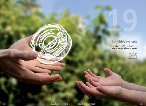
<strong>Belt</strong> <strong>drive</strong> <strong>systems</strong><br />
<strong>Potential</strong> <strong>for</strong> CO 2<br />
<strong>reductions</strong><br />
and how to achieve them<br />
Hermann Stief<br />
Rainer Pflug<br />
Timo Schmidt<br />
Christian Fechler<br />
19<br />
264<br />
<strong>Schaeffler</strong> SYMPOSIUM 2010<br />
<strong>Schaeffler</strong> SYMPOSIUM 2010<br />
265
19 <strong>Belt</strong> <strong>drive</strong><br />
<strong>Belt</strong> <strong>drive</strong><br />
19<br />
Introduction<br />
<strong>Schaeffler</strong> has volume produced components <strong>for</strong><br />
belt <strong>drive</strong> <strong>systems</strong> since 1977. For the past 15 years,<br />
<strong>Schaeffler</strong> has worked on the development of complete<br />
belt <strong>drive</strong> <strong>systems</strong> in timing <strong>drive</strong>s (Figure 1)<br />
as well as in accessory <strong>drive</strong>s (Figure 2).<br />
Tension pulleys and<br />
idler pulleys<br />
One use of INA idler pulleys is to reduce noise in<br />
critical belt spans, to prevent collision problems<br />
with the surrounding structure, to guide the belt<br />
or to increase the angle of belt wrap on neighboring<br />
pulleys. These pulleys have the same rating<br />
life and noise development requirements as belt<br />
tensioning <strong>systems</strong>. For this application, high-precision<br />
single-row ball bearings with an enlarged<br />
grease supply volume have proven sufficient.<br />
If required, double-row<br />
angular contact ball<br />
bearings (Figure 3) are<br />
used that also have an<br />
optimized grease supply<br />
volume. These<br />
bearings are equipped<br />
with high-temperature<br />
rolling bearing greases<br />
and appropriate seals.<br />
Standard catalog bearings<br />
are not as suitable<br />
<strong>for</strong> this application.<br />
The tension pulleys installed<br />
consist of single<br />
or double-row ball<br />
bearings specially developed,<br />
optimized and<br />
manufactured by INA<br />
<strong>for</strong> use in belt <strong>drive</strong> applications.<br />
Depending<br />
on the application,<br />
pulleys made from glass<br />
fiber rein<strong>for</strong>ced polyamide<br />
or corrosion protected<br />
steel can be<br />
added.<br />
Single and double eccentric tensioners<br />
Pulleys<br />
Variable camsha ming<br />
Idler pulleys<br />
Figure 1<br />
Timing <strong>drive</strong><br />
Considering the fact that over 100 million belt<br />
<strong>drive</strong> components are produced annually, this<br />
means that, on average, almost two belt <strong>drive</strong><br />
components manufactured by <strong>Schaeffler</strong> are installed<br />
in every vehicle.<br />
Figure 3<br />
Steel pulley<br />
Thanks to <strong>Schaeffler</strong>’s<br />
highly developed tooling<br />
and manufacturing<br />
technology, the pulleys<br />
made from highly temperature<br />
resistant, glass<br />
fiber rein<strong>for</strong>ced polyamide<br />
(Figure 4) are just as<br />
good as the steel pulleys<br />
when it comes to roundness<br />
and running characteristics<br />
and may offer<br />
significant cost and<br />
weight benefits. Adjusted<br />
dust covers made<br />
from steel or plastic may<br />
also be used.<br />
<strong>Belt</strong>s (preferably by CT)<br />
Figure 5 Products in the timing <strong>drive</strong><br />
19<br />
Figure 2<br />
Accessory <strong>drive</strong><br />
Figure 4<br />
Plastic pulley<br />
Timing <strong>drive</strong><br />
Timing belt <strong>drive</strong>s (Figure 5) that <strong>drive</strong> camshafts<br />
or balancer shafts have been volume produced <strong>for</strong><br />
internal combustion engines <strong>for</strong> 40 years. In older<br />
designs, the timing belt was preloaded via either<br />
an accessory with eccentric bearings in the timing<br />
belt <strong>drive</strong> (e.g. water pumps) or through manually<br />
adjustable, fixed tension pulleys (e.g. eccentric<br />
tensioners).<br />
266 <strong>Schaeffler</strong> SYMPOSIUM 2010<br />
<strong>Schaeffler</strong> SYMPOSIUM 2010 267
19 <strong>Belt</strong> <strong>drive</strong><br />
<strong>Belt</strong> <strong>drive</strong><br />
19<br />
This type of system does not allow <strong>for</strong> optimal adjustment<br />
of the belt <strong>for</strong>ce since neither belt <strong>for</strong>ce<br />
fluctuations resulting from temperature or wear<br />
nor dynamic effects (belt vibrations, impacts from<br />
the valve train) are compensated. Compensation<br />
of such fluctuations and effects by means of automated<br />
belt tensioning <strong>systems</strong> is essential in modern<br />
timing belt <strong>drive</strong>s since this is the only way that<br />
a system life of up to 240 000 km and more (depending<br />
on the engine life) required in today’s automotive<br />
industry can be achieved.<br />
<strong>Belt</strong> <strong>drive</strong> <strong>systems</strong> not optimally preloaded are susceptible<br />
to noise and susceptible to wear. Using an<br />
automated belt tensioning system considerably reduces<br />
preload <strong>for</strong>ce dispersion during initial installation<br />
and also keeps the preload <strong>for</strong>ce across the<br />
engine’s operating temperature range at nearly<br />
consistent levels. Automated belt tensioning <strong>systems</strong><br />
have been used in timing belt <strong>drive</strong>s in internal<br />
combustion engines since the early 90s and<br />
have largely replaced fixed <strong>systems</strong> <strong>for</strong> the reasons<br />
described above.<br />
The above conditions result in the following primary<br />
requirements <strong>for</strong> automated tensioning <strong>systems</strong>:<br />
Mot. fricon torque - CR in Nm<br />
5<br />
4<br />
3<br />
2<br />
1<br />
Figure 6<br />
Reduced fricon - Comparison chain vs. belt<br />
1000 2000 3000 4000 5000 6000<br />
Cranksha speed in 1/min<br />
Chain <strong>drive</strong><br />
<strong>Belt</strong> in oil <strong>drive</strong><br />
Friction curves of chain vs. belt<br />
tion by 1 to 2 %, also decreasing the emission of<br />
carbon dioxide (CO 2<br />
). Figure 6 shows a comparison<br />
of the friction curves <strong>for</strong> timing <strong>drive</strong>s and chain<br />
<strong>drive</strong>s.<br />
A test completed at IFT, Clausthal-Zellerfeld that<br />
compared the measurements <strong>for</strong> a timing belt<br />
Test Program: 4 Cyl. Gasoline Engine<br />
<strong>drive</strong> and a chain <strong>drive</strong> has shown that the timing<br />
belt <strong>drive</strong> has considerable benefits. The test<br />
was per<strong>for</strong>med on a 1.6 liter, 4-cylinder gasoline<br />
engine. The test was initially conducted on the<br />
original version with a timing chain and then<br />
with the timing belt version. The test setup is<br />
shown in Figure 7.<br />
The timing belt in oil has already operated <strong>for</strong><br />
more than 240 000 vehicle kilometers in the vehicle<br />
fleet owned by Continental and thus demonstrated<br />
its endurance capability. This also<br />
means that the oil-resistant timing belt lasts the<br />
entire life of the engine.<br />
It will initially be used <strong>for</strong> oil pump <strong>drive</strong>s and timing<br />
<strong>drive</strong>s. This innovation will later also be developed<br />
<strong>for</strong> additional applications, such as higher<br />
demanding balance shaft <strong>drive</strong>s, to further reduce<br />
CO 2<br />
emissions.<br />
Tension pulleys / pulleys<br />
Accessory <strong>drive</strong><br />
In modern internal combustion engines, accessories<br />
are almost exclusively <strong>drive</strong>n by poly-V belts.<br />
The primary requirements <strong>for</strong> accessory <strong>drive</strong> <strong>systems</strong><br />
(Figure 8) and their automated tensioning<br />
<strong>systems</strong> are listed below:<br />
Automated belt <strong>for</strong>ce adjustment during initial<br />
installation and maintenance (tolerance compensation<br />
of all <strong>drive</strong> components)<br />
Nearly consistent belt <strong>for</strong>ce during the entire<br />
life of the belt <strong>drive</strong> (compensation of belt<br />
elongation and wear)<br />
Nearly consistent belt <strong>for</strong>ce across the entire<br />
engine temperature range (compensation of heat<br />
expansion of all components affecting the <strong>drive</strong>)<br />
Mechanical auto tensioners<br />
Provide simple adjustment of the specified belt<br />
<strong>for</strong>ce during initial installation and maintenance<br />
(compensation of belt, diameter and position<br />
tolerances)<br />
E-Motor<br />
Maintain a defined belt <strong>for</strong>ce that is as<br />
consistent as possible under all operating<br />
conditions <strong>for</strong> the duration of the required<br />
system life (compensation of heat expansion,<br />
belt elongation and wear, consideration of<br />
crankshaft and camshaft dynamics)<br />
Ensure an optimal noise level while also reducing<br />
belt vibrations<br />
Chain <strong>drive</strong><br />
<strong>Belt</strong> <strong>drive</strong><br />
Pulley decoupler<br />
Hydraulic auto tensioner<br />
System tuning together<br />
with ConTech<br />
19<br />
Prevent gear teeth jump<br />
<strong>Potential</strong> <strong>for</strong> CO 2<br />
<strong>reductions</strong><br />
in timing <strong>drive</strong>s<br />
Overunning alternator pulley<br />
Waterpump bearings<br />
Compared to chain <strong>drive</strong>s, both dry and oil lubricated<br />
timing belts, that can be used to <strong>drive</strong> oil<br />
pumps, balance shafts and camshafts, significantly<br />
reduce friction (measurements have determined<br />
up to 30 %), thus helping reduce fuel consumption.<br />
The friction benefit of timing <strong>drive</strong>s compared to<br />
chain <strong>drive</strong>s can reduce a vehicle’s fuel consump-<br />
Figure 7<br />
Test setup<br />
Figure 8<br />
Products in accessory <strong>drive</strong>s<br />
268 <strong>Schaeffler</strong> SYMPOSIUM 2010<br />
<strong>Schaeffler</strong> SYMPOSIUM 2010 269
19 <strong>Belt</strong> <strong>drive</strong><br />
<strong>Belt</strong> <strong>drive</strong><br />
19<br />
Reduction of dynamic belt <strong>for</strong>ce peaks<br />
Minimization of slip, noise and belt wear<br />
Rating life increase <strong>for</strong> the entire belt <strong>drive</strong><br />
system<br />
Optimal reliability of the overall belt <strong>drive</strong><br />
system<br />
Minimization of friction loss in the overall system<br />
Modern, optimally adjusted accessory <strong>drive</strong> <strong>systems</strong><br />
(Figure 8) are maintenance free and can run<br />
<strong>for</strong> up to 240 000 km, given by optimal system development.<br />
Mechanical belt tensioning<br />
units<br />
Mechanical belt tensioning units (Figure 9) represent<br />
a cost-optimized solution <strong>for</strong> automatically<br />
tensioned poly-V belt <strong>drive</strong>s. The required<br />
Component overview<br />
Thrust washer<br />
Single self-lubricang<br />
thermoplasc plain bearing<br />
– opmized NVH behaviour<br />
– balanced load distribuon<br />
Lever arm<br />
Torsion spring<br />
without legs<br />
Figure 9<br />
Mechanical belt tensioner<br />
belt preload <strong>for</strong>ce is usually generated by the<br />
torque of a torsion spring as well as the lever<br />
arm and the tension pulley. The damping package<br />
consists of a friction element (disk, ring and<br />
cone) that is preloaded by the torsion spring. As<br />
the lever arm moves, a relative motion in the<br />
damping package is generated, causing friction<br />
and, consequently, damping. The belt preload<br />
<strong>for</strong>ce (via the spring’s torque) and damping are<br />
adjusted to match the application. The materials<br />
used allow consistent damping values to be<br />
achieved via the temperature and frequency and<br />
with minimal run-in effects. Different designs<br />
permit optimum usage of the available design<br />
package.<br />
Hydraulic belt tensioning<br />
<strong>systems</strong><br />
Protecve cap<br />
Pulley bolt<br />
Plasc pulley<br />
alternave:<br />
steel pulley<br />
Radial loaded fricon element<br />
self-lubricang thermoplasc<br />
Backplate / sleeve unit<br />
Hydraulic belt tensioning <strong>systems</strong> provide a solution<br />
<strong>for</strong> poly-V belt <strong>drive</strong>s with high requirements.<br />
They consist of<br />
a hydraulic component<br />
with an integrated<br />
pressure spring<br />
and hydraulic leakage<br />
gap damping as well<br />
as a lever arm with an<br />
attached tension pulley.<br />
The hydraulic<br />
leakage gap damping<br />
acts in a controlled<br />
way and in proportion<br />
to the speed, causing<br />
damping to be generated<br />
only when needed.<br />
The optimal adjustment<br />
of the<br />
required belt preload<br />
<strong>for</strong>ce to the relevant<br />
application is carried<br />
out via the integrated<br />
pressure spring and<br />
the converted lever<br />
ratio. The required<br />
damping is set by selecting<br />
the leakage<br />
gap. The properties of<br />
the hydraulic oil used<br />
ensure the lowest<br />
Figure 10 Hydraulic belt tensioner<br />
possible damping<br />
temperature dependency<br />
in combination with excellent resistance<br />
to aging – all with hardly any wear. An example<br />
design is shown in Figure<br />
10.<br />
Overrunning<br />
alternator<br />
pulley<br />
Alternators have the<br />
largest inertial torque<br />
in an accessory <strong>drive</strong>,<br />
greatly affecting belt<br />
<strong>drive</strong> behavior. An<br />
overrunning alternator<br />
pulley decouples<br />
its inertial torque<br />
from the cyclic irregularities<br />
of the crankshaft<br />
in an internal<br />
combustion engine.<br />
Tensioner with<br />
Rubber bellows<br />
(RSEHB)<br />
Tensioner with<br />
Piston rod seal<br />
(RSEHK)<br />
Outer sleeve<br />
Support bearing<br />
Clutch cage<br />
Needle rollers<br />
Support bearing 2<br />
Advantages<br />
The positive effects on the accessory <strong>drive</strong> include:<br />
Minimization of belt vibrations<br />
Reduction of <strong>for</strong>ce peaks in belt <strong>drive</strong>s<br />
Reduction of tensioner movement<br />
Increase in belt life<br />
Improved noise behavior in the belt <strong>drive</strong><br />
Reduction of belt slip on the alternator pulley<br />
during upshift (particularly in fast shifting dualclutch<br />
and automatic transmissions)<br />
Less strain on the overall system during engine<br />
start and stop-and-start function<br />
Preload <strong>for</strong>ce reduction in the overall system,<br />
leading to reduced CO 2<br />
and frictional loss<br />
Decoupling function<br />
The large mass of the generator cannot follow<br />
the high irregularities of the crankshaft at engine<br />
start and <strong>drive</strong> resonances. Thus it comes to<br />
differences of rotation angle speeds of crankshaft<br />
to alternator. Contrary to a rigid wheel the<br />
overrunning alternator pulley opens in overhauling<br />
direction. The alternator mass and their influences<br />
are decoupled from the accessory<br />
Inner sleeve with<br />
Ramp profile<br />
Figure 11 Overrunning alternator pulley<br />
Sealing ring<br />
Hub<br />
Clutch unit<br />
Pulley<br />
Sealing frontside<br />
Cap<br />
19<br />
270 <strong>Schaeffler</strong> SYMPOSIUM 2010<br />
<strong>Schaeffler</strong> SYMPOSIUM 2010 271
19 <strong>Belt</strong> <strong>drive</strong><br />
<strong>Belt</strong> <strong>drive</strong><br />
19<br />
<strong>drive</strong>. In addition, the overrunning alternator<br />
pulley decouples the alternator’s inertial torque<br />
during a significant engine speed deceleration<br />
(shifting gears, upshifting).<br />
Structural design<br />
The overrunning alternator pulley (Figure 11)<br />
consists of a pulley with an outside diameter<br />
suitable <strong>for</strong> using a poly-V belt, a one-way<br />
clutch unit with bearing supports, an inner ring<br />
and two seals. Following installation, an end<br />
cover is snapped onto the front of the alternator<br />
shaft to protect it from ambient media (e.g.<br />
penetration of contamination, salt water deposits).<br />
A modular system has been developed <strong>for</strong> overrunning<br />
alternator pulleys to provide an economical<br />
and flexible solution <strong>for</strong> customer inquiries.<br />
The one-way clutch unit and the seal<br />
components are standard parts.<br />
Unlike spring decouplers, an overrunning alternator<br />
pulley does not have its own resonant frequency<br />
and does not have to be adjusted to<br />
varying alternator sizes.<br />
<strong>Potential</strong> <strong>for</strong> CO 2<br />
reduction<br />
in accessory <strong>drive</strong>s<br />
The details of accessory <strong>drive</strong> components described<br />
above show that a wide range of parameters<br />
must be considered to achieve the<br />
functional operation and rating life of the overall<br />
system. Targeted investigations through dynamic<br />
simulation with Sim<strong>drive</strong> 3D and testing<br />
have yielded belt preload as the main<br />
influencing parameter with regard to friction<br />
losses in the accessory <strong>drive</strong>. <strong>Belt</strong> preload has a<br />
significant effect on:<br />
Bearing friction in tension pulleys and idler<br />
pulleys<br />
<strong>Belt</strong> expansion<br />
Loss in %<br />
opmal range<br />
Pretension in N<br />
Figure 12 Friction curve<br />
Load at 1st crankshaft bearing (is not considered<br />
in analysis below)<br />
When the functional limits and system tolerances<br />
are considered, an engine-specific optimal<br />
preload range can be determined (Figure<br />
12).<br />
Figure 13 compares potential savings using a<br />
sample <strong>drive</strong> layout. Assuming a basic system<br />
with a mechanical belt tensioner and a preload<br />
of 350 N required <strong>for</strong> this system, the potential<br />
savings when using an alternator decoupler can<br />
be determined. Some savings can be achieved<br />
compared to the basic system without changing<br />
the belt preload. If an alternator decoupler<br />
with an overrunning alternator pulley (“OAP” in<br />
Figure 14) or a springelastic<br />
alternator decoupler<br />
is introduced,<br />
the preload can potentially<br />
be reduced<br />
to 280 N, resulting in<br />
friction and loss savings<br />
of 14 to 20 % in<br />
the <strong>drive</strong> system (Figure<br />
14).<br />
Even greater savings<br />
can be achieved when<br />
a pulley decoupler<br />
is used right on the<br />
crankshaft itself.<br />
Compared to the basic<br />
system, a frictional<br />
loss reduction of up<br />
to 36 % can be achieved in the <strong>drive</strong> system<br />
(Figure 15). In this example, a preload of 230 N<br />
ensures optimal friction reduction while maintaining<br />
the system’s functional operation and<br />
rating life.<br />
Reference: mech. tensioner, no decoupling, 350 N<br />
Decoupling: Pulley Decoupler<br />
Pretension: 350 N<br />
0 %<br />
-10 %<br />
-20 %<br />
-30 %<br />
-40 %<br />
-4.6 % -3.4 %<br />
Possible decrease of stac pretension<br />
Accessories base load<br />
Accessories full load<br />
Pulley decoupler<br />
Decoupling: OAP<br />
Pretension: 350 N<br />
0 %<br />
- 5 %<br />
-10 %<br />
-15 %<br />
-20 %<br />
-1.3 %<br />
Pulley Decoupler<br />
230 N<br />
-35.7 % -24.2 %<br />
Figure 15 <strong>Potential</strong> savings <strong>for</strong> friction losses<br />
Possible decrease<br />
of stac pretension<br />
Reference: mech. tensioner, no decoupling, 350 N<br />
-1.5 % -1.0 % -1.6 %<br />
Accessories base load<br />
Accessories full load<br />
GEN Decoupler<br />
350 N<br />
Figure 14 <strong>Potential</strong> savings <strong>for</strong> friction losses<br />
OAP<br />
280 N<br />
GEN Decoupler<br />
280 N<br />
-20.3 % -14.2 % -20.0 % -15.5 %<br />
double-clutch transmissions. LuK also solves<br />
torsional vibration problems in internal combustion<br />
engines and has developed the product<br />
group of engine dampers. The internal crankshaft<br />
damper (ICD) was presented during the<br />
2002 LuK Symposium [1]. The ICD has been volume<br />
produced successfully <strong>for</strong> several years in<br />
addition to other engine dampers. Development<br />
activities currently focus on the reduction<br />
of torsional vibrations <strong>for</strong> belt <strong>drive</strong>s. One related<br />
development is the Pulley decoupler.<br />
cranksha<br />
damper<br />
pulley<br />
decoupling<br />
19<br />
<strong>Belt</strong> bending<br />
Contact losses between the belt and the pulley,<br />
particularly the radial compression of the belt<br />
Bearing friction within all accessories (is not<br />
considered in analysis below)<br />
Figure 13 Simulated <strong>drive</strong><br />
LuK is a well-known specialist <strong>for</strong> transmission<br />
and clutch components and has an extensive<br />
portfolio of products <strong>for</strong> the reduction of torsional<br />
vibrations in vehicle power trains. These<br />
products include dampers in clutch disks, dualmass<br />
flywheels, torque converter clutches and<br />
Figure 16 Pulley decoupler with integrated crankshaft<br />
damper<br />
272 <strong>Schaeffler</strong> SYMPOSIUM 2010<br />
<strong>Schaeffler</strong> SYMPOSIUM 2010 273
19 <strong>Belt</strong> <strong>drive</strong><br />
<strong>Belt</strong> <strong>drive</strong><br />
19<br />
The decoupled pulley on the crankshaft of the internal<br />
combustion engine has two main functions:<br />
1. Driving the belt <strong>drive</strong> <strong>for</strong> accessory <strong>drive</strong>s while<br />
simultaneously decoupling this belt <strong>drive</strong> system<br />
from the cyclic irregularities of the crankshaft.<br />
2. Providing damping <strong>for</strong> the torsional vibrations<br />
resulting from the eigenfrequencies in the<br />
crankshaft – flywheel vibration system.<br />
The function and structure of the two partial <strong>systems</strong><br />
(Figure 16) are described below.<br />
Speed irregularity (2. order) in 1/min<br />
Speed irregularity (2. order) in 1/min<br />
150<br />
125<br />
100<br />
75<br />
50<br />
25<br />
0<br />
150<br />
125<br />
100<br />
75<br />
50<br />
25<br />
0<br />
<strong>Belt</strong> <strong>drive</strong> with OAP on alternator<br />
(4. gear with load on accessory)<br />
0 500 1000 1500 2000 2500 3000<br />
Engine speed in 1/min<br />
Cranksha<br />
Pulley<br />
OAP<br />
Alternator<br />
<strong>Belt</strong> <strong>drive</strong> with decoupling on cranksha<br />
(4. gear with load on accessory)<br />
0 500 1000 1500 2000 2500 3000<br />
Engine speed in 1/min<br />
Cranksha<br />
Pulley<br />
Alternator<br />
Figure 17 <strong>Belt</strong> <strong>drive</strong> measurements<br />
<strong>Belt</strong> <strong>drive</strong> decoupler<br />
The periodic ignition in the internal combustion<br />
engine generates a cyclic irregularity that is applied<br />
to the accessories via the belt in the <strong>for</strong>m of torsional<br />
vibrations. When the engine operates at the<br />
eigenfrequencies of the belt <strong>drive</strong> system, the system<br />
can be excited to generate resonance vibrations.<br />
A pulley decoupler mounted on the crankshaft is<br />
used to minimize belt vibrations induced by<br />
these cyclical irregularities of the crankshaft.<br />
The measurements in Figure 17 show a comparison<br />
of a belt <strong>drive</strong> system with overrunning alternator<br />
pulley (OAP) and fixed pulley on the<br />
crankshaft with a belt <strong>drive</strong> decoupling system<br />
(the second order of the engine speed <strong>for</strong> each).<br />
The isolation of the entire belt <strong>drive</strong> can be improved<br />
significantly by the decoupler on the<br />
crankshaft.<br />
In many applications, the first eigenfrequency of a<br />
belt <strong>drive</strong> without decoupling is in a speed range of<br />
1000 and 1500 1/min. With the pulley decoupler<br />
a further spring system is added to the vibration<br />
system. This lowers the natural frequency clearly<br />
below the idle speed of the internal combustion<br />
engine, and the belt <strong>drive</strong> is operated in the abovecritical<br />
range, resulting in a reduced load <strong>for</strong> all<br />
components in the belt <strong>drive</strong>.<br />
Decoupled pulleys <strong>for</strong> crankshafts available on<br />
today’s market contain spring elements made<br />
Pulley<br />
1. Spring<br />
2. Spring<br />
Cranksha<br />
3. Spring<br />
Figure 18 Cross section of pulley decoupler<br />
Figure 19 Exploded diagram of pulley decoupler<br />
from elastomers. Although these elastomers<br />
represent a relatively inexpensive material <strong>for</strong><br />
spring elements, their functional operation and<br />
lifetime greatly depend on the temperature and<br />
number of load cycles. As requirements increase<br />
(increasing cyclic irregularities of the engine,<br />
larger number of engine starts, higher drag<br />
torques, rising ambient temperatures), the application<br />
range <strong>for</strong> “elastomer decouplers” becomes<br />
more and more limited.<br />
In the LuK Pulley decoupler, the spring element design<br />
utilizes coil springs in the component shown<br />
(Figure 18 and 19). The three arc springs and the<br />
<strong>for</strong>ce transmission are guided in two plastic cups<br />
located under the belt track. The pulley is guided<br />
with a plain bearing on the hub.<br />
In the decoupler and <strong>for</strong> the entire belt <strong>drive</strong>, an<br />
eigenfrequency via the arc-shaped springs is<br />
shown. This frequency is below idle speed and allows<br />
the required above-critical operation of the<br />
belt <strong>drive</strong>. When starting the engine, this eigenfrequency<br />
must be passed through. In an unfavorable<br />
case, a resonance may be generated that<br />
coincides with the eigenfrequency<br />
in the<br />
dual-mass flywheel –<br />
power train combination.<br />
Since a relief angle<br />
function is<br />
integrated in the pulley<br />
decoupler, resonances<br />
are prevented<br />
from passing through<br />
the eigenfrequencies<br />
of the belt <strong>drive</strong> in<br />
their earliest stages.<br />
The required clearance<br />
angle is realized in the<br />
component by an adjusted<br />
torsion capability<br />
between the plastic cups and the contacting<br />
sheet metal parts.<br />
This results in a characteristic curve <strong>for</strong> the decoupler<br />
(Figure 20) composed of several different<br />
curves including the characteristic curve of the arcshaped<br />
spring package C2 as well as two relief angle<br />
curves. Transitional springs have been integrated<br />
in the component <strong>for</strong> the transition between<br />
the curves that, via their serial connection with the<br />
arc-shaped springs, result in a soft transition C1 <strong>for</strong><br />
the entire spring curve. Isolation is further improved<br />
by reducing the total spring rate in the lower<br />
moment range.<br />
With the design and curve structure described<br />
above, there is an additional option of a bidirectional<br />
transmission of the moment in the decoupler.<br />
Besides driving the accessories in the belt<br />
<strong>drive</strong>, the decoupler can be used in applications<br />
that call <strong>for</strong> a start function of the internal combustion<br />
engine or a boost function via the alternator<br />
in the belt <strong>drive</strong>. In these cases, the moment<br />
flow runs in the opposite direction in the<br />
belt <strong>drive</strong>.<br />
Torque<br />
Figure 20 Characteristic curve of a pulley decoupler<br />
C 1<br />
Angle<br />
C 2<br />
19<br />
274 <strong>Schaeffler</strong> SYMPOSIUM 2010<br />
<strong>Schaeffler</strong> SYMPOSIUM 2010 275
19 <strong>Belt</strong> <strong>drive</strong><br />
<strong>Belt</strong> <strong>drive</strong><br />
19<br />
Figure 21 Dual pulley decoupler <strong>for</strong> alternator start<br />
and 2-belt <strong>systems</strong><br />
For applications that require a higher torque <strong>for</strong><br />
the alternator start or boost functions compared to<br />
the actual drag function, an asymmetrical characteristic<br />
curve can be achieved in a dual damper<br />
(Figure 21).<br />
Torsional vibration damping<br />
A torsional vibration damper has been integrated<br />
in the assembly <strong>for</strong> another main function (Figure<br />
16). This is used to reduce resonance vibrations<br />
in the crankshaft that are generated by the ignition<br />
frequency of the engine [2]. Here the crankshaftflywheel<br />
vibration system is excited in several eigenfrequencies.<br />
The torsional vibration damper will be tuned on<br />
the first eigenfrequency within a range from 300 to<br />
400 Hz. Depending on the number of cylinders,<br />
crankshaft design and the masses of the crankshaft<br />
and the flywheel, the eigenfrequencies are excited<br />
by the dominant exciter orders in the engine's entire<br />
speed range. In this process, the flywheel vibrates<br />
against the crankshaft with the attached<br />
masses such as connecting rods and pistons.<br />
This eigenfrequencies can be dampened by a free<br />
mass via a spring and damping element at the free<br />
end of the crankshaft. In small or medium series<br />
engines, this is usually a mass ring that is coupled<br />
to the crankshaft by means of a vulcanized or<br />
pressed-in rubber track [3]. In larger engines, this<br />
application may also include viscous dampers. The<br />
optimal adjustment of the mass, spring and damping<br />
reduces resonance vibrations in the crankshaft<br />
and achieves an improvement in the NVH behavior<br />
as well as lifetime of the crankshaft.<br />
System evaluation with engine and<br />
power train<br />
Pulley decouplers and the adjacent accessories<br />
and components in a belt <strong>drive</strong> are designed using<br />
state-of-the-art simulation tools. Besides Sim<strong>drive</strong><br />
3D the <strong>Schaeffler</strong> <strong>Group</strong> also uses DyFaSIM.<br />
This program was developed by LuK and is the result<br />
from many years of development and design<br />
of torsion dampers and dual-mass flywheels. The<br />
program permits the simulation of the entire vehicle<br />
power train from the engine through the vehicle<br />
to the wheel as well as belt <strong>drive</strong>s and their<br />
behavior.<br />
Using the simulation technology employed <strong>for</strong> the<br />
development of the dual-mass flywheel [4] allows<br />
a complete evaluation by expanding the power<br />
train models to include models <strong>for</strong> belt <strong>drive</strong> <strong>systems</strong>.<br />
Interactions of the belt <strong>drive</strong> with the engine,<br />
the coupled single or dual mass flywheel and<br />
the power train can be integrated into the investigation.<br />
When parameters such as slip, belt vibrations, belt<br />
tensioner <strong>for</strong>ces and bearing <strong>for</strong>ces in the accessories<br />
are considered, simulations allow an optimal<br />
belt decoupler design decoupling the belt <strong>drive</strong><br />
from the excitations of the internal combustion engine.<br />
This results in a reduction of accessory losses<br />
which in turn leads to a reduction in fuel consumption<br />
and CO 2<br />
emissions <strong>for</strong> the internal combustion<br />
engine.<br />
Summary<br />
In the past, high-quality belt <strong>drive</strong> components<br />
were often regarded as the necessary “problem<br />
solvers” in difficult applications. In future, highly<br />
efficient complete <strong>systems</strong> (Figure 22) in timing<br />
<strong>drive</strong>s and accessory <strong>drive</strong>s will be indispensable to<br />
increase com<strong>for</strong>t and reduce CO 2<br />
emissions as<br />
much as possible.<br />
Timing <strong>drive</strong>s must be<br />
reanalyzed to take low<br />
friction characteristics<br />
into account. The benefits<br />
of a chain <strong>drive</strong> are<br />
counteracted by the disadvantage<br />
of increased<br />
friction among others.<br />
Here, results clearly<br />
point to the benefits of<br />
timing belt <strong>drive</strong>s.<br />
In accessory <strong>drive</strong>s, decoupling<br />
in the crank<br />
shaft pulley provides significant<br />
advantages <strong>for</strong><br />
the entire belt <strong>drive</strong>. Reducing<br />
the applied cyclic<br />
irregularities allows the<br />
load <strong>for</strong> all components<br />
in the <strong>drive</strong> to be reduced.<br />
In combination<br />
with the pulley decoupler<br />
including arcshaped<br />
steel springs,<br />
potential <strong>for</strong> optimization<br />
can be seen. The<br />
potential savings shown<br />
in Figure 23 are possible.<br />
The skillful application<br />
and combination of<br />
products in <strong>Schaeffler</strong>’s<br />
portfolio allows the<br />
greatest possible CO 2<br />
savings to be achieved<br />
in belt <strong>drive</strong> <strong>systems</strong>.<br />
Literature<br />
Technical ef<strong>for</strong>t<br />
[1] Gerhardt, F.; Fechler, C.; Lehmann, S.; Langeneckert,<br />
H.: Internal Crankshaft Damper;<br />
7th LuK Syposium, 2002<br />
[2] van Basshuysen; Schäfer: Handbuch Verbrennungsmotor,<br />
2. Auflage, Vieweg-Verlag,<br />
2002, pp. 78-79<br />
Combinaon of belt <strong>drive</strong> components and fuel consumpon<br />
Hydraulic belt tensioner + Pulley decoupler<br />
Mechanical belt tensioner + Pulley decoupler<br />
Hydraulic belt tensioner + OAP<br />
Mech. belt tensioner + OAP or hydr. belt tensioner<br />
Mechanical belt tensioner<br />
Fixed tensioner<br />
Figure 22 <strong>Potential</strong> <strong>for</strong> optimization<br />
Loss in %<br />
Figure 23 Optimization curve<br />
Potenal <strong>for</strong> fuel consumpon / CO 2 reducon<br />
Pretension in N<br />
Mech. tensioner<br />
Hydr. tensioner<br />
Efficiency<br />
Mech. tensioner + OAP/Decoupler<br />
Hydr. tensioner + OAP/Decoupler<br />
Mech. tensioner + Pulley decoupler<br />
Hydr. tensioner + Pulley decoupler<br />
[3] Hafner, Maass: Torsionsschwingungen in<br />
der Verbrennungskraftmaschine, Band 4,<br />
1. Auflage ,Springer-Verlag, 1985, p. 361 ff.<br />
[4] Fidlin, A.; Seebacher, R.: DMF simulation<br />
techniques; 8th LuK Symposium, 2006<br />
19<br />
276 <strong>Schaeffler</strong> SYMPOSIUM 2010<br />
<strong>Schaeffler</strong> SYMPOSIUM 2010 277


