Thermal-Magnetic Circuit Breaker 4220-T... 3 - ETA
Thermal-Magnetic Circuit Breaker 4220-T... 3 - ETA
Thermal-Magnetic Circuit Breaker 4220-T... 3 - ETA

Create successful ePaper yourself
Turn your PDF publications into a flip-book with our unique Google optimized e-Paper software.
Description<br />
Typical applications<br />
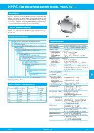
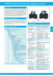
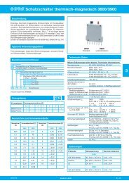
<strong>Thermal</strong>-<strong>Magnetic</strong> <strong>Circuit</strong> <strong>Breaker</strong> <strong>4220</strong>-T...<br />
Single, double and three pole thermal-magnetic circuit breakers with<br />
high rupture capacity to UL 489 (5 kA), EN/IEC 60934 (6kA) and UL<br />
1077 (5 kA). With toggle actuation, positively trip-free mechanism, a<br />
choice of characteristic curves and a wide range of current ratings in<br />
finely graded steps from 0.1 A through 32 A. Auxiliary contacts (make or<br />
break contacts) are optionally available. Track-mountable design, width<br />
only 12.5 mm. Ease of wiring by means of an integral busbar concept:<br />
line entry busbar LINE+ and signal busbars/signal jumpers.<br />
Protection of power supplies, equipment and cables in centralised<br />
control systems and in decentralised installations serving automation,<br />
petro-chemical, power plant, steel industry and similar industrial<br />
applications.<br />
Ordering Information<br />
Type number<br />
<strong>4220</strong> thermal-magnetic high performance circuit breaker<br />
Mounting<br />
T1 track-mounting<br />
Number of poles<br />
1 single pole<br />
2 double pole<br />
3 three pole<br />
Additional feature<br />
0 without actuator guard<br />
1 with actuator guard<br />
Main terminals<br />
K0 screw terminals 16 mm 2 / 10 mm 2<br />
Characteristic curve<br />
F1 thermal-magnetic, extremely fast, DC<br />
F2 thermal-magnetic, fast, AC/DC<br />
M1 thermal-magnetic, medium delay, AC/DC<br />
T1 thermal-magnetic, long delay, AC/DC<br />
Auxiliary contacts<br />
H0 without<br />
H1 with auxiliary contacts in all poles<br />
H2 with auxiliary contacts only in pole 1 (2-pole plus)<br />
H3 with auxiliary contacts only in poles 1+3 (3-pole plus)<br />
H4 with auxiliary contacts only in pole 2 (3-pole plus)<br />
H5 with auxiliary contacts only in the last pole<br />
H6 with auxiliary contacts only in poles 1+2 (3-pole plus)<br />
Auxiliary contact function<br />
0 without<br />
2 make contact (N/O)<br />
3 break contact (N/C)<br />
A pole 1 make contact, all other poles break<br />
contacts (2-pole plus)<br />
B poles 1+2 make contacts, other poles break<br />
contacts (3-pole plus)<br />
C pole 1 break contact, other poles make<br />
contacts (2-pole plus)<br />
Auxiliary contacts – terminal design<br />
0 without<br />
1 screw terminals 1 mm 2<br />
Voltage rating<br />
A ≤ AC 277 V or ≤ DC 60 V<br />
Current rating range<br />
0.1...32 A<br />
Approval logo (optional)<br />
V UL 489 (1-pole)<br />
<strong>4220</strong> - T1 1 0 - K0 M1- H1 2 1 - A - 10 A -V ordering example<br />
<strong>4220</strong>-T...<br />
single pole three pole<br />
Technical data<br />
For further details please see catalogue section: Technical Information<br />
Voltage rating AC 240 V; 3 AC 415 V (50/60 Hz); DC 60 V<br />
UL: AC 120 V; AC 277 V; 3 AC 415 V;<br />
DC 60 V<br />
Current rating range 0.1...32 A<br />
Auxiliary circuit<br />
Typical life<br />
DC 10 - 30 V, 10 - 500 mA, resistive<br />
IEC 60934 AC 240/415 V 1,000 cycles at 1 x IN , ind. load<br />
UL 489<br />
UL 1077<br />
AC 240 V: 6,000 cycles at 1 x IN , inductive load<br />
DC 60 V: 6,000 cycles at 1 x IN , resistive load<br />
AC 120 V: 6,000 cycles at 1 x IN , inductive load<br />
AC 277/480 V 3,000 cycles at 1 x IN , inductive load<br />
AC 277 V: 6,000 cycles at 1 x IN , inductive load<br />
DC 60 V: 6,000 cycles at 1 x IN , resistive load<br />
Ambient temperature -30...+60 °C (-22...+140 °F, T60)<br />
Storage temperature -40…+60 °C (-40…+140 °F)<br />
Insulation co-ordination IEC 60664 2.5 kV / 2<br />
re-inforced insulation in the operating area<br />
Dielectric strength IEC 60934<br />
operating area test voltage AC 3,000 V<br />
(reinforced insulation)<br />
pole to pole<br />
main circuit to<br />
test voltage AC 1,500 V<br />
auxiliary circuit test voltage AC 1,500 V<br />
open main circuit test voltage AC 1,500 V<br />
open auxiliary circuit test voltage AC 250 V<br />
Insulation resistance<br />
Interrupting capacity<br />
> 100 MΩ (DC 500 V)<br />
Inc PC1 AC 240 V, AC 240/415 V: 6,000 A<br />
IEC 60934<br />
Interrupting capacity<br />
DC 60 V: 6,000 A<br />
UL 489 AC 120 V: 5,000 A<br />
Interrupting capacity AC 277 V, AC 277/480 V: 5,000 A<br />
UL 1077 DC 60 V: 5,000 A<br />
Protection class operating area IP30<br />
(IEC 60529) terminal area IP00<br />
Vibration (sinusoidal) ± 0.38 mm (10-57 Hz), 5 g (57-500 Hz)<br />
test to IEC 60068-2-6, test Fc,<br />
10 frequency cycles/axis<br />
Shock 25 g (11 ms)<br />
test to IEC 60068-2-27, test Ea<br />
Corrosion 96 hrs in 5 % salt mist,<br />
test to IEC 60068-2-11,test Ka<br />
Humidity 240 hrs in 95 % RH,<br />
to IEC 60068-2-78, test Cab<br />
Housing material moulded material<br />
Mounting<br />
Mounting dimension<br />
on symmetrical rail to EN 50022-35x7.5<br />
(w x h x d) 12.5 x 89.3 x 87.1 (per pole)<br />
Issue D www.e-t-a.de<br />
3 - 47<br />
3
3<br />
Technical data<br />
3 - 48<br />
<strong>Thermal</strong>-<strong>Magnetic</strong> <strong>Circuit</strong> <strong>Breaker</strong> <strong>4220</strong>-T...<br />
LINE terminal (LINE and/or DC+)<br />
screw terminals<br />
max. cable cross section<br />
M5<br />
flexible with wire end ferrule w/wo plastic sleeve 1 – 16 mm²<br />
multi-lead connection<br />
(2 identical cables)<br />
flexible with wire end ferrule without plastic sleeve 1 – 6 mm²<br />
flexible with TWIN wire end ferrule with plastic sleeve 0.75 – 10 mm²<br />
wire stripping length 14 mm<br />
tightening torque<br />
LOAD terminal<br />
2.5 – 3 Nm<br />
screw terminals<br />
max. cable cross section<br />
M4<br />
flexible with wire end ferrule w/wo plastic sleeve 0.5 – 10 mm<br />
multi-lead connection<br />
(2 identical cables)<br />
flexible with wire end ferrule without plastic sleeve 0.5 – 2.5 mm²<br />
flexible with TWIN wire end ferrule with plastic sleeve 0.5 – 6 mm²<br />
wire stripping length 10 mm<br />
tightening torque 1.2 – 1.4 Nm<br />
Auxiliary contact terminals<br />
screw terminals<br />
max. cable cross section<br />
M2<br />
flexible with wire end ferrule w/wo plastic sleeve 0.25 – 0.75 mm²<br />
multi-lead connection<br />
(2 identical cables)<br />
flexible with wire end ferrule without plastic sleeve 0.25 – 0.34 mm²<br />
wire stripping length 6 mm<br />
tightening torque 0.22 – 0.25 Nm<br />
Mass approx. 90 g per pole with aux. contact<br />
Current ratings and typical internal resistance values<br />
Current rating (A) Internal resistance (Ω)<br />
trip curve F1 F2 M1 T1<br />
fast fast medium delay long delay<br />
DC only AC + DC AC + DC AC + DC<br />
0.1 166 148 122 104<br />
0.2 45 41 34 29<br />
0.3 19 17 14 12<br />
0.4 12 11 7.9 7.3<br />
0.5 6.8 5.6 4.7 4.2<br />
0.6 4.9 4.5 3.7 3.4<br />
0.8 2,9 2.7 2.1 1.7<br />
1 1.8 1.6 1.3 1.1<br />
1.5 0.93 0.76 0.62 0.58<br />
2 0.47 0.40 0.34 0.31<br />
2.5 0.30 0.27 0.23 0.21<br />
3 0.22 0.20 0.17 0.15<br />
3,5 0.17 0.16 0.13 0.12<br />
4 0.11 0.11 0.084 0.077<br />
5 0.086 0.082 0.066 0.062<br />
6 0.064 0.062 0.053 0.049<br />
8 0.029 0.026 ≤ 0.02 ≤ 0.02<br />
10 ≤ 0.022 ≤ 0.02 ≤ 0.02 ≤ 0.02<br />
12 ≤ 0.02 ≤ 0.02 ≤ 0.02 ≤ 0.02<br />
15 ≤ 0.02 ≤ 0.02 ≤ 0.02 ≤ 0.02<br />
16 ≤ 0.02 ≤ 0.02 ≤ 0.02 ≤ 0.02<br />
18 ≤ 0.02 ≤ 0.02 ≤ 0.02 ≤ 0.02<br />
20 ≤ 0.02 ≤ 0.02 ≤ 0.02 ≤ 0.02<br />
25 ≤ 0.02 ≤ 0.02 ≤ 0.02 ≤ 0.02<br />
32 ≤ 0.02 ≤ 0.02 ≤ 0.02 ≤ 0.02<br />
Dimensions<br />
80.2<br />
3.157<br />
73.2<br />
2.882<br />
6.9 43.5<br />
1.713<br />
37.3<br />
1.47<br />
nx12.5<br />
.492<br />
12.3<br />
.484<br />
www.e-t-a.de Issue D<br />
operating area<br />
(reinforced insulation)<br />
mounting area<br />
(standard insulation)<br />
44 45.3<br />
1.732 1.783<br />
snap-in socket<br />
protection against<br />
for symmetrical<br />
brush contact:<br />
rail EN 50022-35x7,5 remove slide from the<br />
bottom of the device<br />
.272<br />
label see accessories<br />
45<br />
1.77<br />
OFF ON<br />
Installation drawing<br />
allowable mounting position: vertical<br />
Internal connection diagrams<br />
...-H121-...<br />
unit I<br />
unit II<br />
unit III<br />
auxiliary contact<br />
terminal M2<br />
max. 1.5 mm 2<br />
movable<br />
snap-in hook<br />
OFF position ON position<br />
line (Si) Si make contact line (Si)<br />
0 I 1 13 (N/O)<br />
0 I 1 13<br />
I ><br />
2<br />
2<br />
...-H131-...<br />
OFF position ON position<br />
line (Si) Si break contact line (Si)<br />
0 I 1 11 (N/C)<br />
0 I 1 11<br />
I ><br />
2<br />
14 14<br />
(Si) (Si)<br />
I ><br />
12 12<br />
(Si) (Si)<br />
This is a metric design and millimeter dimensions take precedence ( mm )<br />
inch<br />
I ><br />
2<br />
slot for<br />
signal busbar<br />
main contact<br />
terminal M4<br />
max. 10 mm2
Termination examples<br />
<strong>Thermal</strong>-<strong>Magnetic</strong> <strong>Circuit</strong> <strong>Breaker</strong> <strong>4220</strong>-T...<br />
<strong>4220</strong>-T with busbars and signal busbars<br />
(auxiliary contacts connected in parallel)<br />
busbars<br />
busbars<br />
signal busbars<br />
(parallel connection)<br />
<strong>4220</strong>-T with busbars and jumpers<br />
(auxiliary contacts connected in parallel)<br />
busbars<br />
jumpers<br />
(parallel connection)<br />
<strong>4220</strong>-T with busbars and signal busbars<br />
(auxiliary contacts connected in serie)<br />
jumpers<br />
(series connection<br />
shifted by 1 in relation<br />
to the opposite side)<br />
insert slide for protection<br />
against brush contract<br />
on breaker side<br />
insert slide for protection<br />
against brush contract<br />
on breaker side<br />
insert slide for protection<br />
against brush contract<br />
on breaker side<br />
Busbars, signal busbars and jumpers: see accessories<br />
This is a metric design and millimeter dimensions take precedence ( mm )<br />
inch<br />
Accessories<br />
Description Part number<br />
busbar red, 500 mm length, X 222 611 01<br />
can be cut to length<br />
busbar grey, 500 mm length, X 222 611 02<br />
can be cut to length<br />
signal busbar blue, 500 mm length, X 222 005 01<br />
can be cut to length<br />
signal busbar red, 500 mm length, X 222 005 02<br />
can be cut to length<br />
signal busbar grey, 500 mm length, X 222 005 03<br />
can be cut to length<br />
signal busbar grey X 222 486 25<br />
(packing unit 25 pcs)<br />
Label (packing unit 50 pcs) X 222 977 50<br />
or from Phoenix ZBF 12<br />
busbar<br />
X 222 611 01 / red, 500 mm length, can be cut to length<br />
X 222 611 02 / grey, 500 mm length, can be cut to length r<br />
signal busbar<br />
X 222 005 01 / blue, 500 mm length, can be cut to length<br />
X 222 005 02 / red, 500 mm length, can be cut to length r<br />
X 222 005 03 / grey, 500 mm length, can be cut to length<br />
or<br />
jumper<br />
X 222 486 25 grey<br />
label<br />
X 222 977 50<br />
or from Phoenix ZBF 12<br />
signal busbar<br />
X 222 005 01 / blue, 500 mm length, can be cut to length<br />
X 222 005 02 / red, 500 mm length, can be cut to length<br />
X 222 005 03 / grey, 500 mm length, can be cut to length<br />
or<br />
jumper<br />
X 222 486 25 grey<br />
push in busbars and slide<br />
for protection against brush<br />
contact to be flush with<br />
housing sides<br />
push up signal busbars<br />
and jumpers<br />
against housing<br />
protection against<br />
brush contact:<br />
remove slide from the<br />
bottom of the device<br />
Issue D www.e-t-a.de<br />
3 - 49<br />
3
3<br />
F1 thermal, magnetic<br />
fast (DC)<br />
Trip time in seconds<br />
3 - 50<br />
10000<br />
1000<br />
100<br />
10<br />
1<br />
0,1<br />
0,01<br />
0,001<br />
<strong>Thermal</strong>-<strong>Magnetic</strong> <strong>Circuit</strong> <strong>Breaker</strong> <strong>4220</strong>-T...<br />
1 2 4 6 810 20 40 6080100<br />
...times rated current<br />
M1 thermal, magnetic<br />
medium delay (AC/DC)<br />
Trip time in seconds<br />
10000<br />
1000<br />
100<br />
10<br />
1<br />
0,1<br />
0,01<br />
0,001<br />
1 2 4 6 810 20 40 6080100<br />
...times rated current<br />
Typical time/current characteristics<br />
60 °C<br />
23 °C<br />
-30 °C<br />
60 °C<br />
23 °C<br />
-30 °C<br />
F2 thermal, magnetic<br />
fast (AC/DC)<br />
Trip time in seconds<br />
Trip time in seconds<br />
10000<br />
1000<br />
100<br />
10<br />
1<br />
0,1<br />
0,01<br />
0,001<br />
10000<br />
1000<br />
100<br />
10<br />
1<br />
0,1<br />
0,01<br />
0,001<br />
1 2 4 6 810 20 40 6080100<br />
...times rated current<br />
T1 thermal, magnetic<br />
long delay (AC/DC)<br />
The time/current characteristic curve depends on the ambient temperature prevailing. In<br />
order to eliminate nuisance tripping, please multiply the circuit breaker current ratings by<br />
the derating factor shown below. See also section Technical information.<br />
Ambient temp. °F<br />
°C<br />
Approvals<br />
-22<br />
-30<br />
-4<br />
-20<br />
+14<br />
-10<br />
+32<br />
0<br />
+50<br />
+10<br />
+73.4<br />
+23<br />
+86<br />
+30<br />
+104<br />
+40<br />
+122<br />
+50<br />
1 2 4 6 810 20 40 6080100<br />
+140<br />
+60<br />
Derating factor 0.76 0.79 0.83 0.88 0.93 1 1.04 1.12 1.22 1.35<br />
Test authority Voltage ratings Current ratings<br />
UL 489 AC 120 V 0.1...32 A (only 1-pole)<br />
VDE (EN 60934) AC 240 V;<br />
AC 240/415 V;<br />
DC 60 V<br />
UL 1077 AC 277 V;<br />
AC 277/480 V;<br />
DC 60 V<br />
0.1...32 A<br />
0.1...32 A<br />
...times rated current<br />
60 °C<br />
23 °C<br />
-30 °C<br />
60 °C<br />
23 °C<br />
-30 °C<br />
<strong>Magnetic</strong> tripping currents are increased by 30 % on DC<br />
supplies.<br />
When several devices are mounted together, an air gap between<br />
each is recommended. If this is not possible, each device should<br />
carry only 80 % of its rating.<br />
All dimensions without tolerances are for reference only. In the interest of improved design,<br />
performance and cost effectiveness the right to make changes in these specifications<br />
without notice is reserved.Product markings may not be exactly as the ordering codes.<br />
Errors and omissions excepted.<br />
www.e-t-a.de Issue D