Download - Schneider Electric
Download - Schneider Electric
Download - Schneider Electric

You also want an ePaper? Increase the reach of your titles
YUMPU automatically turns print PDFs into web optimized ePapers that Google loves.
ReactiVar ®<br />
Table of Contents<br />
Description<br />
Page<br />
ReactiVar ® Power Factor Correction Capacitors<br />
AV4000 & AV5000 Automatic<br />
Capacitor Banks<br />
• Low Voltage Fixed Unfused Capacitor Banks<br />
• Low Voltage Fixed Fused Capacitor Banks<br />
• Automatic Power Factor Capacitor Banks<br />
• Anti-Resonant and Filtering Capacitor Banks<br />
• LV Transient Free Reactive Compensation Banks<br />
• CT Selection and Dimensions<br />
• Medium Voltage Fixed and Automatic Capacitor Banks<br />
• AccuSine ® PCS Active Harmonic Filter<br />
• Hybrid VAR Compensator (HVC)<br />
• Power Factor Correction Selection Data<br />
11-2<br />
11-3<br />
11-4<br />
11-5<br />
11-6<br />
11-7<br />
11-8<br />
11-9<br />
11-10<br />
11-12<br />
DE11 CAPACITORS<br />
12/08<br />
DE11-1
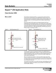
LV Dry Fixed Fused Power Factor Correction Capacitors<br />
Class 5810<br />
Low Voltage Fixed Capacitors<br />
ReactiVar ® fixed low voltage capacitors are ideally suited for power factor correction<br />
applications where the load does not change or where the capacitor is switched with the<br />
load, such as the load side of a motor starter. ReactiVar ® fixed capacitors are best suited<br />
for applications where there are no harmonic currents or voltages present.<br />
Fixed<br />
Capacitors are<br />
best suited for<br />
use on<br />
electrical<br />
systems with<br />
no voltage or<br />
current<br />
harmonics.<br />
Features:<br />
• Environmentally Friendly: ReactiVar ® capacitors are constructed with a dry type<br />
metalized Polypropylene capacitor element with no liquid dielectrics. There is no risk of<br />
fluid leakage or environmental pollution and no need for a drip pan.<br />
• Low Loss, Long Life: The design features less than 0.5W/kVAR losses, including<br />
discharge resistors.<br />
• Attractive finish: Capacitor units feature a textured powder paint finish, ASA 49 gray.<br />
Units are constructed of 14 gauge steel and are suitable for floor or wall mounting.<br />
DE11 CAPACITORS<br />
Application Note: Capacitors are a low impedance path for the<br />
harmonic currents produced by variable frequency drives, motor soft<br />
starters, welders, computers, PLCs, robotics and other electronic<br />
equipment. These harmonic currents can be drawn into the capacitor<br />
causing it to overheat, shortening its life. Furthermore, the resonant<br />
circuit formed by shunt capacitors coupled with system inductances<br />
(motors and transformers) can amplify harmonic currents and voltages<br />
in the electrical network. This amplification can cause nuisance fuse<br />
operation and/or damage to electrical equipment including capacitors<br />
and other electronic devices. If power factor correction in the presence<br />
of harmonics is required, please contact your nearest Square D/<br />
<strong>Schneider</strong> <strong>Electric</strong> sales office for assistance.<br />
Unfused 600V e 3 phase/60 Hz unit<br />
Kvar rating Indoor NEMA 1 unit Rated Current<br />
Recommended Copper<br />
wire size (90 o C) d Recommended circuit protection device rating a<br />
at 600V Catalogue number Enclosure bc at 600V Qty x AWG Fuse Circuit breaker<br />
10.5 PFCD6010 1 10.1 14 15 15<br />
12.5 PFCD6012 1 12.0 12 20 20<br />
15 PFCD6015 1 14.4 12 20 20<br />
21 PFCD6020 1 20.2 10 30 30<br />
23 PFCD6022 1 22.1 10 30 30<br />
25 PFCD6025 1 24.0 8 35 35<br />
27.5 PFCD6027 1 26.4 8 40 40<br />
30 PFCD6030 1 28.8 8 40 40<br />
35.5 PFCD6035 2 34.1 8 50 50<br />
40 PFCD6040 2 38.4 6 60 60<br />
45 PFCD6045 2 43.2 6 60 60<br />
50 PFCD6050 2 48.0 6 65 65<br />
60 PFCD6060 2 57.6 4 80 80<br />
70.5 PFCD6070 3 67.7 4 100 100<br />
75 PFCD6075 3 72.0 3 100 100<br />
80 PFCD6080 3 76.8 3 125 125<br />
90 PFCD6090 3 86.4 2 125 125<br />
100 PFCD6100 4 96.0 2 150 150<br />
120 PFCD6120 4 115.2 1/0 175 175<br />
125 PFCD6125 5 120.0 1/0 175 175<br />
150 PFCD6150 5 144.0 2/0 200 200<br />
175 PFCD6175 5 168.0 4/0 250 250<br />
180 PFCD6180 5 172.8 4/0 250 250<br />
a: Consult local electrical codes for proper sizing of molded case circuit breaker frame or disconnect switch rating.<br />
b: Unit size 1, 2 and 3 can be wall mounted.<br />
c: Refer to page DE11-3 for dimensions.<br />
d: Conductor should be copper and rated 90 o C min. Refer to local electrical codes for proper wire size.<br />
e: 480V is available upon request. Contact <strong>Schneider</strong> <strong>Electric</strong> PQC group for details.<br />
DE11-2<br />
12/08
LV Dry Fixed Fused Power Factor Correction Capacitors<br />
Class 5810<br />
Low Voltage Fixed Fused Capacitors with Blown Fuse Indicators<br />
In addition to the comprehensive Multiple Protection System designed into the New ReactiVar ® fixed, low voltage capacitors, fused units feature a fast acting current limiting<br />
fuse in each phase. Blown fuse indicators are included as standard on indoor (NEMA Type 1) enclosures. While fuses are not required to protect the capacitor elements,<br />
external over current protection may be required by the local electrical code for protection of the conductors feeding the capacitors. Consult your local electrical code for<br />
installation instructions.<br />
Fused 600V e 3 phase/60 Hz unit<br />
Kvar rating Indoor NEMA 1 unit Rated Current<br />
Recommended Copper<br />
wire size (90 o C) d Recommended circuit protection device rating a<br />
at 600V Catalogue number Enclosure bc at 600V Qty x AWG Fuse Circuit breaker<br />
10.5 PFCD6010F 1 10.1 14 15 15<br />
12.5 PFCD6012F 1 12.0 12 20 20<br />
15 PFCD6015F 1 14.4 12 20 20<br />
21 PFCD6020F 1 20.2 10 30 30<br />
23 PFCD6022F 1 22.1 10 30 30<br />
25 PFCD6025F 1 24.0 8 35 35<br />
27.5 PFCD6027F 1 26.4 8 40 40<br />
30 PFCD6030F 1 28.8 8 40 40<br />
35.5 PFCD6035F 2 34.1 8 50 50<br />
40 PFCD6040F 2 38.4 6 60 60<br />
45 PFCD6045F 2 43.2 6 60 60<br />
50 PFCD6050F 2 48.0 6 65 65<br />
60 PFCD6060F 2 57.6 4 80 80<br />
70.5 PFCD6070F 3 67.7 4 100 100<br />
75 PFCD6075F 3 72.0 3 100 100<br />
80 PFCD6080F 3 76.8 3 125 125<br />
90 PFCD6090F 3 86.4 2 125 125<br />
100 PFCD6100F 4 96.0 2 150 150<br />
120 PFCD6120F 4 115.2 1/0 175 175<br />
125 PFCD6125F 5 120.0 1/0 175 175<br />
150 PFCD6150F 5 144.0 2/0 200 200<br />
175 PFCD6175F 5 168.0 4/0 250 250<br />
180 PFCD6180F 5 172.8 4/0 250 250<br />
a: Consult local electrical codes for proper sizing of molded case circuit breaker frame or disconnect switch rating.<br />
b: Unit size 1, 2 and 3 can be wall mounted.<br />
c: Refer to page DE11-3 for dimensions.<br />
d: Conductor should be copper and rated 90 o C min. Refer to local electrical codes for proper wire size.<br />
e: 480V is available upon request. Contact <strong>Schneider</strong> <strong>Electric</strong> PQC group for details.<br />
DE11 CAPACITORS<br />
NEMA Type 1 Enclosure dimensions<br />
Size H W D<br />
No. IN mm IN mm IN mm<br />
1 30.26 769 20 508 16.88 429<br />
2 42.95 1091 20 508 16.88 429<br />
3 55.64 1413 20 508 16.88 429<br />
4 42.95 1091 36 914 16.88 429<br />
5 55.64 1413 36 914 16.88 429<br />
16.875<br />
16.875<br />
16.150<br />
14.500 1.065<br />
32.150<br />
14.500 1.065<br />
14.075<br />
14.075<br />
H<br />
H<br />
3.500<br />
0.125<br />
3.500<br />
0.125<br />
18.000<br />
20.000<br />
14.875 34.000<br />
16.875<br />
36.000<br />
14.875<br />
16.875<br />
12/08<br />
DE11-3
PFC Capacitor Banks<br />
Class 5830<br />
Low Voltage (LV) Standard<br />
AutomaticCapacitor Banks with Main<br />
Lugs or Main Breakers<br />
Main Features:<br />
DE11 CAPACITORS<br />
The AV4000 and AV5000<br />
are suitable for use where<br />
harmonic generating loads<br />
are less than 15% of the total<br />
connected load.<br />
The AV4000 and AV5000 standard automatic power<br />
factor correction banks are designed for centralized<br />
power factor correction to supply varying amounts of<br />
reactive power required to compensate for changing load<br />
conditions. The AV4000 and AV5000 banks are ideally<br />
suited for facility electrical distribution systems with TDD<br />
(total harmonic current distortion) < = 5% and THD(V)<br />
(total harmonic voltage distortion) < = 3%. An advanced<br />
microprocessor-based recative power controller<br />
measures plant power factor via a single remote CT.<br />
Plus, it switches capacitor modules in and out of service<br />
to maintain a user-selected target power factor.<br />
Application Assistance:<br />
The <strong>Schneider</strong> <strong>Electric</strong> Power Quality Correction Group<br />
provides engineering assistance for the application of<br />
capacitors in harmonic rich environments. Specialists at<br />
Square D can assess the likelihood of application<br />
problems and arrange for more detailed study if required.<br />
Solutions can include computer modeling and system<br />
simulation. Our application engineers can make all the<br />
arrangements for system studies, custom engineering,<br />
installation and commissioning, as required by the<br />
application. Contact <strong>Schneider</strong> <strong>Electric</strong> sale office for<br />
detail equipment quotation assistance.<br />
For dimension reference, see page DE11-7.<br />
• Modular construction; free standing QED switchboard<br />
enclosures contain up to 500 KVAR per section and allow for<br />
easy future expansion<br />
• Standard offering available up to 400 KVAR at 208/240 Vac,<br />
1000 KVAR at 480 or 600 Vac<br />
• Main lugs or main breaker section at your choice<br />
• Dry capacitor element design eliminates risk of fluid leakage,<br />
environmental hazard and drip pans<br />
• Capacitor rated contactors are designed specifically for the<br />
switching of capacitive currents and feature a patented<br />
capacitor precharge circuit that exceeds air-core reactor<br />
transient dampening<br />
• Three different microprocessor controller options provide<br />
functionality and control sophistication<br />
• Backlit display on controller displays actual PF, alarms,<br />
number of steps energized and much more<br />
• Rugged design — units are constructed with removable<br />
steel panels over heavy gauge steel frame<br />
• Available in Type NEMA 1 indoor and NEMA 3R outdoor<br />
enclosures<br />
• Indoor units are finished with ASA 49 grey textured paint<br />
finish<br />
• For application up to 200 kVAR max., 480 or 600 V (main<br />
lugs, top entry only), the AV4000 offers compact and cost<br />
effective alternative.<br />
Equipment specification:<br />
Voltage:<br />
240, 480, 600 Vac standard, 208, 380, 415 Vac available<br />
Kvar rating:<br />
up to 1000 KVAR (depending on voltage rating)<br />
Ambient temperature: -5°C to 46°C<br />
Average temperature limit:
PFC Capacitor Banks<br />
Class 5860<br />
Low Voltage Anti-Resonant and Filtering Automatic Capacitor Banks with Main Lugs<br />
and Breaker<br />
ReactiVar ® AV6000 anti-resonant and AV7000 harmonic filtering automatic switched capacitor banks are specifically<br />
designed for networks containing harmonic energies which would otherwise damage standard fixed or automatic<br />
capacitor banks.<br />
The problem: Harmonics are a natural by-product of non-linear loads such as variable frequency drives, motor soft<br />
starters, welders, uninterruptable power supplies, robotics, PLCs and other electronic devices. Harmonics introduce<br />
higher-than-60 Hz current and voltage components into the electrical distribution system. Capacitors are a low<br />
impedance path for these higher frequency components and thus will absorb these harmonic energies. Combinations<br />
of capacitors and system inductances (motors and transformers) can form series and parallel tuned circuits which can<br />
resonate at certain frequencies. The harmonics produced by non-linear loads can excite a standard capacitor bank into<br />
resonance. The resonance can magnify currents and voltages, causing system wide damage and equipment failure.<br />
This problem is growing in prevalence.<br />
The solution: Anti-Resonant Automatic Switched Capacitor Banks<br />
The AV6000 anti-resonance capacitor bank’s primary function is power factor correction. Iron core reactors are added<br />
in series with the capacitor modules. The 3 phase reactors are custom designed and manufactured at our factory under<br />
tight tolerance specifically for the AV6000. The reactors tune the bank below the first dominant harmonic (usually the<br />
5th, or 300 Hz). Below the tuning point, the system appears capacitive and thus corrects power factor. Above the tuning<br />
point, the system appears Inductive and thus resonance is minimized. The AV6000 design has the added advantage of<br />
removing up to 50% of the 5th harmonic to reduce overall voltage distortion.<br />
Harmonic Filtering Automatic Switched Capacitor Banks<br />
The need for an AV7000 is usually determined by a power quality specialist. Although the AV7000 looks identical to the<br />
AV6000, its primary function is harmonic mitigation, with power factor correction being a secondary benefit. The<br />
distinction between an AV6000 and an AV7000 is the tuning point. By definition, if the tuning point of the capacitor/<br />
reactor combination is within ±10% of the target harmonic it is intended to absorb, it is referred to as a filter. If the tuning<br />
point is outside the ±10% limit, it is referred to as an anti-resonant system. As the tuning point of the system<br />
approaches the target harmonic, its effectiveness at absorbing increases. Hence, the need to classify its functionality.<br />
The PQc group should always be consulted prior to recommending it to customers.<br />
Main Features<br />
• Standard offering available up to 1200 KVAR at 480 or 600 Vac<br />
• Capacitor modules are designed with higher than standard voltage and current ratings to provide long life on systems with high<br />
harmonic energies. Reactors are designed to operate at 115°C rise over a maximum 40°C ambient temperature.<br />
• In addition to the standard features provided in the AV5000 systems, the Reactors in the AV6000 have an embedded thermistor<br />
temperature detector. The stage will shut down and annunciate if the reactor should overheat, usually a result of excessive<br />
harmonic energies.<br />
Application Assistance<br />
The <strong>Schneider</strong> <strong>Electric</strong> Power Quality Correction Group provides engineering assistance for the application of<br />
capacitors in harmonic rich environments. Specialists at Square D can assess the likelihood of application problems<br />
and arrange for more detailed study if required. Solutions can include computer modeling and system simulation.<br />
Depending on the network, the solution may include de-tuned banks (AV6000) or fully filtered banks (AV7000). Our<br />
application engineers can make all the arrangements for system studies, custom engineering, installation and<br />
commissioning, as required by the application. Contact <strong>Schneider</strong> <strong>Electric</strong> sales office for detail equipment quotation<br />
assistance.<br />
For dimension reference, see page DE11-7.<br />
Equipment specification:<br />
DE11 CAPACITORS<br />
Voltage:<br />
480, 600 Vac standard, 380, 415 Vac available<br />
Kvar rating:<br />
up to 1200 KVAR (depending on voltage rating)<br />
Ambient temperature: -5°C to 46°C<br />
Average temperature limit:
PFC Capacitor Banks<br />
Class 5870<br />
DE11 CAPACITORS<br />
Low Voltage Transient Free Reactive Compensation<br />
Capacitor Banks<br />
Square D ® ReactiVar ® Transient Free Reactive Compensation (TFRC) anti-resonant (A/<br />
BT6000) Systems and filtering system (A/BT7000) are ideally suited for use on electrical<br />
systems where connected equipment is extremely sensitive to variations in the supply<br />
voltage.<br />
The problem: Capacitor systems featuring electromechanical contactors generate Voltage<br />
transients on the electrical network when switching capacitor stages on/off, even when<br />
current limiting or tuning reactors are employed. Transients can impair the operation of<br />
sensitive equipment, including programmable logic controllers, variable speed drives,<br />
computers and UPS systems. In sensitive networks such as hospitals, data processing<br />
centers, airports and many manufacturing environments, any transient, however slight, may<br />
not be acceptable.<br />
The solution: TFRC systems feature an advanced controller to precisely activate<br />
electronic switching elements to connect capacitor stages and avoid the creation of<br />
transients. Transient free switching also reduces wear on capacitors due to switching and<br />
will result in longer life for the overall capacitor system. With a response time of less than<br />
ten seconds to load changes, TFRC systems reduce the kVA demand on the transformer<br />
and will eliminate utility imposed penalties for low power factor. Depending on the level of<br />
harmonic producing (non-linear) devices on the network, two TFRC systems are available:<br />
the AT6000 anti-resonant (de-tuned) system and the AT7000 filtered system. Non-linear<br />
loads include variable speed drives, UPS systems, soft starters and other power electronic<br />
devices. The anti-resonant system will absorb up to 50% of the fifth harmonic current while<br />
the filtered system will absorb up to 80% of the fifth harmonic current, improving overall<br />
network conditions.<br />
Main Features:<br />
Standard offering up to 1350 KVAR at 480 or 600 Vac<br />
• Transient free switching of capacitor steps<br />
Electronic switching elements yield an unlimited number of switching operations<br />
• Three different microprocessor controller options provide a choice in functionality and control<br />
sophistication<br />
Backlit display on controller displays actual PF, alarms, number of steps energized and much more<br />
• Heavy duty dry capacitor element design provides no risk of fluid leakage, no environmental<br />
pollution and no need for drip pans<br />
• The Reactors have an embedded thermistor temperature detector. The stage will shut down and<br />
annunciate if the reactor should overheat, usually a result of excessive harmonic energies<br />
Units are constructed with removable heavy duty steel panels over a 12 gauge steel frame.<br />
• Indoor Type 1 units finished with ASA 49 gray polyester paint. Other colours available.<br />
Application Assistance<br />
The <strong>Schneider</strong> <strong>Electric</strong> Power Quality Correction Group provides engineering assistance<br />
for the application of capacitors in harmonic rich environments. Specialists at Square D can<br />
assess the likelihood of application problems and arrange for more detailed study if<br />
required. Solutions can include computer modeling and system simulation. Our application<br />
engineers can make all the arrangements for system studies, custom engineering,<br />
installation and commissioning, as required by the application. Contact <strong>Schneider</strong> <strong>Electric</strong><br />
sales office for detail equipment quotation assistance.<br />
For dimension reference, see page DE11-7.<br />
Equipment specification:<br />
Voltage:<br />
480, 600 Vac standard, 380, 415 Vac available<br />
Kvar rating:<br />
up to 1350 Kvar (depending on voltage rating)<br />
Load change response time:
Low Voltage Capacitor Banks<br />
Sub 600 kVAR Sub<br />
Feed Automatic Feed<br />
Capacitor<br />
Bank<br />
Main Transformer<br />
Main Breaker<br />
External Current<br />
Transformer<br />
Ratio XXXX/5<br />
Sub<br />
Feed<br />
Single Line (Typical)<br />
Diagram 1<br />
Sub<br />
Feed<br />
CT Selection Guide for Class 5830, 5860 & 5870<br />
The current transformer is located on a phase A bus or<br />
cable at the main service entrance as illustrated in<br />
Diagram 1. The CT should be sized for the maximum load<br />
current. The CT should be installed upstream of the<br />
capacitor bank and plant loads to measure the combined<br />
current.<br />
CT catalogue number: TRAI••••SCc c where •••• is<br />
current rating code of bus/cable and c c is window size<br />
code. Codes are listed in table to the right.<br />
e.g. TRAI1000SC07 is a CT for 1000 A bus with 7" x 4"<br />
window.<br />
Current Rating of Bus/Cable<br />
Amperes<br />
Rating Code<br />
••••<br />
Class 5830, 5860, 5870<br />
Class 5840, 5841<br />
7" x 4" Size<br />
Code<br />
c c<br />
Window Size<br />
11" x 4" Size<br />
Code<br />
c c<br />
300 0300 07 11<br />
400 0400 07 11<br />
500 0500 07 11<br />
600 0600 07 11<br />
750 0750 07 11<br />
800 0800 07 11<br />
1000 1000 07 11<br />
1200 1200 07 11<br />
1500 1500 07 11<br />
1600 1600 07 11<br />
2000 2000 07 11<br />
2500 2500 07 11<br />
3000 3000 07 11<br />
3500 3500 07 11<br />
4000 4000 07 11<br />
5000 5000 N/A 11<br />
6000 6000 N/A 11<br />
Enclosure dimensions<br />
24 MIN. CLEARANCE<br />
32.00<br />
32.00<br />
New product dimension information<br />
will be updated via on-line version<br />
in 2009.<br />
DE11 CAPACITORS<br />
60.00<br />
18.00<br />
SUPPLIED BUT<br />
FIELD FITTED<br />
CABLE ENTRY<br />
BOX C/W<br />
REMOVABLE<br />
CABLE ENTRY<br />
PLATE QTY (1)<br />
AIR FLOW<br />
REMOVABLE<br />
LIFTING LUGS<br />
36. MIN. CLEARANCE<br />
91.50<br />
93.50<br />
32.00<br />
32.00<br />
35.00<br />
AT6000<br />
12/08<br />
DE11-7
Medium Voltage Capacitor Systems<br />
Class 5840, 5841<br />
Power factor correction, harmonic mitigation, and voltage support in medium voltage<br />
electrical systems. Custom engineered for steady and rapidly fluctuating loads.<br />
ReactiVar ® Medium Voltage Fixed Power Factor Capacitors<br />
The ReactiVar ® MVC fixed capacitors are ideally suited for power factor correction in<br />
applications where the load does not change or where the capacitor is switched with the<br />
load, such as the load side of a motor contactor. Reactivar capacitors are available up to 300<br />
kVAR as individual units, and up to 600 kVAR in banks. Unfused or fused (2 fuses)<br />
assemblies are available. Other ranges available upon request.<br />
Features:<br />
• Fused and unfused applications<br />
• Up to 600 kVAR, 4800 V<br />
• Metallized polypropylene film capacitors for low dielectric loss<br />
• Internally mounted discharge resistors<br />
• Operating temperature range of –400°C to +450°C<br />
• Built to UL, CSA and IEC standards<br />
• Available in indoor (Type 1/12) and outdoor (Type 3R) enclosures<br />
• Painted ASA 61 gray<br />
DE11 CAPACITORS<br />
MVC systems are suitable for<br />
power factor correction of steady<br />
harmonic-free motor loads.<br />
MV5000 systems are suitable for use<br />
where harmonic generating loads<br />
are less than 15% of the total connected load.<br />
MV6000 systems are suitable for use<br />
where harmonic generating loads<br />
exceed 15% of the total connected load.<br />
MV7000 systems are suitable for use<br />
where harmonic generating loads<br />
exceed 50% of the total connected load.<br />
MVHVC High-Speed compensation systems<br />
are designed for compensation<br />
of rapidly fluctuating loads<br />
Lead time: 12–14 weeks typical<br />
Prices & assistance: Call PQc Group at 1-800-265-3374 or email<br />
pqc@ca.schneider-electric.com<br />
Literature: for additional information refer to www.reactivar.com<br />
Reactivar Medium Voltage Metal Enclosed Automatic Capacitor<br />
Banks (MV5000/MV6000/MV7000)<br />
The Reactivar medium voltage automatic capacitor banks are ideally suited for centralized<br />
power factor correction and/or harmonic filtering in applications where plant loading is<br />
constantly changing, resulting in the need for varying amounts of reactive power. All MV<br />
capacitor systems are a custom-engineered to meet project specific application and<br />
installation needs.<br />
Features:<br />
• Standard metal enclosures available up to 20,000 kVAR, 5/15 kV, 50/60 Hz.<br />
• The Square D HVL load interrupter switch (fused or unfused).<br />
• Externally fused <strong>Schneider</strong> <strong>Electric</strong> PROPIVAR or Cooper capacitors with excellent<br />
life due to high temperature withstand, small temperature rise, chemical stability,<br />
overvoltage and overcurrent withstand. (Internally fused capacitor available upon<br />
request).<br />
• Three-bushing capacitor cells connected in delta available up to 5 kV. Two-bushing<br />
capacitor cells connected in ungrounded wye for higher voltages.<br />
• Current limiting capacitor fuses with blown fuse pop-up indicators.<br />
• Current limiting reactors in multi-step MV5000 standard systems to limit high<br />
capacitor inrush currents.<br />
• Iron core reactors in MV6000 de-tune banks to prevent resonance and remove up to<br />
50% of the 5th harmonic.<br />
• Heavy-duty iron core reactors in MV7000 filtered banks for effective 5th harmonic<br />
filtering.<br />
• Available in Type 1 indoor and 3R outdoor enclosure types.<br />
• Key interlocking system forces sequential operation of the controls, non-load break<br />
switch (or circuit breaker) and ground switches.<br />
• Superior Square D Varlogic ® microprocessor based power factor controller.<br />
• The <strong>Schneider</strong> <strong>Electric</strong> SEPAM relay provides unbalance, overvoltage and overload<br />
protection.<br />
Lead time: 16–20 weeks typical<br />
Prices & assistance: Call PQc Group at 1-800-265-3374 or email<br />
pqc@ca.schneider-electric.com<br />
Literature: for additional information refer to www.reactivar.com<br />
DE11-8<br />
12/08
AccuSine ® PCS AHF<br />
Class 5820<br />
AccuSine PCS—208–480 Va, 50/60 Hz<br />
The problem:<br />
High levels of harmonics generated by non-linear loads can have significant negative<br />
impact in the facility electrical system. It can cause malfunction of the equipment, disrupt<br />
plant operation, thus, resulting loss of productivity.<br />
Harmonic filtering:<br />
The AccuSine Power Correction System (PCS) is Active Harmonic Filter (AHF) which<br />
actively injects opposite harmonics current on the source side of the load and it:<br />
• Decreases harmonic related overheating of cables, switchgear and transformers<br />
• Reduces downtime caused by nuisance thermal tripping of protective devices<br />
• Increases electrical network reliability and reduces operating costs<br />
• Corrects to the 50th harmonic, reduce harmonics level to meet IEEE 519, IEC 61000 3-4, and<br />
UK G5/4-1 standards.<br />
• Compensates entire network or specific loads depending on installation point<br />
Power Factor Correction and Dynamic VAR Compensation:<br />
AccuSine PCS features a 100 microsecond response providing for dynamic VAR injection<br />
to reduce voltage sags created by inductive load switching. In addition, AccuSine PCS<br />
can inject peak current at 2.25 times its rms current rating for 3 cycles. AccuSine PCS<br />
can also operate in a dual mode where current is first injected to reduce hamonics and<br />
any excess current capacity is used to improve the power factor.<br />
Other Features:<br />
• Independent phase compensation<br />
• UL, CE, ABS, and CSA approved<br />
• Parallel connection allows for easy retrofit and installation of multiple units for large networks<br />
• Response to load fluctuations begins in 100 microseconds with 1/2 cycle for full response to step<br />
load changes<br />
• 50, 100 and 300 A models for 208–480 V. Other voltages available.<br />
Accusine PCS Sizing<br />
For proper sizing of AccuSine units, contact the <strong>Schneider</strong> <strong>Electric</strong> Power Quality<br />
Correction Group at 1-800-265-3374. To expedite the product selection process, please<br />
have a single line diagram and/or details of the application including sizes of<br />
transformers, non-linear and linear loads, and any existing filters and capacitors.<br />
Rated Max. Reactive<br />
Enclosure<br />
Exterior Dimensionsb<br />
Current Power (kVAR) Frequency Catalogue<br />
A (rms)<br />
(Hz)<br />
Number<br />
Price<br />
H W D<br />
Rating Style Cable Entry<br />
208 V 400V 480 V IN mm IN mm IN mm<br />
Weight<br />
Lbs (kg)<br />
50/60 PCS050D5N1<br />
50 PCS050D5N15S<br />
NEMA 1 Wall Mount Bottom 48.0 1219 20.7 526 18.5 470 250 (114)<br />
60 PCS050D5N16S<br />
50/60 PCS050D5N12De<br />
50 18 34.6 41.6<br />
50 PCS050D5N125SCe<br />
NEMA 12<br />
60 PCS050D5N126SDe<br />
50 PCS050D5CE305SCce IP30 (CE Certified) Floor Standingd Top/Bottom 75.0 1905 31.5 801 23.8 605 661 (300)<br />
50 PCS050D5CE545SCce IP54 (CE Certified)<br />
50 PCS050D5IP305SCce IP30<br />
50 PCS050D5IP545SCce IP54<br />
50/60 PCS100D5N1<br />
50 PCS100D5N15S<br />
NEMA 1 Wall Mount Bottom 64.9 1648 20.7 526 18.5 470 350 (159)<br />
60 PCS100D5N16S<br />
50/60 PCS100D5N12De<br />
100 36 69.2 83.1<br />
50 PCS100D5N125SCe<br />
NEMA 12<br />
60 PCS100D5N126SDe<br />
50 PCS100D5CE305SCce IP30 (CE Certified)<br />
Top/Bottom 75.0 1905 31.5 801 23.8 605 771 (350)<br />
50 PCS100D5CE545SCce IP54 (CE Certified)<br />
50 PCS100D5IP305SCe IP30<br />
50 PCS100D5IP545SCe IP54<br />
50/60 PCS300D5N1<br />
50 PCS300D5N15S<br />
NEMA 1 Floor Standingd Top 75.3 1913 31.5 801 19.6 497 775 (352)<br />
60 PCS300D5N16S<br />
50/60 PCS300D5N12De<br />
300 108 207.8 249.4<br />
50 PCS300D5N125SCe<br />
NEMA 12<br />
60 PCS300D5N126SDe<br />
50 PCS300D5CE305SCce IP30 (CE Certified)<br />
Top/Bottom 90.7 2303 39.4 1000 31.7 805 1212 (550)<br />
50 PCS300D5CE545SCce IP54 (CE Certified)<br />
50 PCS300D5IP305SCe IP30<br />
50 PCS300D5IP545SCe IP54<br />
a Other voltages available. Contact your nearest <strong>Schneider</strong> <strong>Electric</strong> sales office. Multiple units can be connected in parallel for larger capacities.<br />
b Dimensions and weights are approximate. Do not use for construction. For actual dimensions, contact your nearest Square D/<strong>Schneider</strong> <strong>Electric</strong> sales office.<br />
c CE Certified units meet EMC Directive 89/336 EEC.<br />
d Floor standing units include a door-interlocked main disconnect.<br />
e C = 380-415 V fan, D = 480 V fan.<br />
DE11 CAPACITORS<br />
NOTE: Refer to page DE11-10 for CT details.<br />
12/08<br />
DE11-9
Hybrid VAR Compensator (HVC)<br />
Class 5890<br />
DE11 CAPACITORS<br />
100 kVAR 100 kVAR 100 kVAR<br />
PASSIVE<br />
HVC Topology (Typical)<br />
Main<br />
Breaker<br />
(Optional)<br />
AccuSine<br />
EVC<br />
300 Ampere<br />
ACTIVE<br />
The Hybrid VAR Compensator (HVC) is ideally suited for industrial facilities with<br />
power quality or production problems caused by rapidly changing load demands<br />
typical of highly cyclical loads such as welders, mining conveyors and heavy<br />
stamping machines.<br />
The problem:<br />
Traditional capacitor systems have a minimum response time of five to ten seconds<br />
to load fluctuations. As a result of this limitation, uncompensated faster loads can<br />
produce voltage instability, voltage flicker, increased losses and poor power factor<br />
which reduces the electric supply capacity. Problems can often be seen inside the<br />
facility, on the utility feeder to the facility or in neighboring facilities. Problems can<br />
include:<br />
• Poor weld quality or reduced weld line productivity (due to restrikes or interlock<br />
weld controls)<br />
• Failure to start motor loads (due to voltage sag on startup)<br />
• Undervoltage tripping of sensitive loads (Robots, PLCs, VFDs)<br />
• Lighting flicker and/or HID lighting shutdown<br />
• Overloaded distribution equipment (cyclical current pulses may exceed the<br />
rated current of the distribution equipment)<br />
• Poor power factor and associated utility demand charges<br />
• High harmonic levels<br />
Ultra-Fast Reactive Power Solution:<br />
• The Hybrid VAR Compensator is ideally suited for power factor correction and<br />
voltage sag support in many applications where conventional systems are not<br />
suitable:<br />
• One cycle (16.7 ms) or less for full response<br />
• Infinite VAR resolution<br />
• Compensates for large inductive inrush currents<br />
• Transient free compensation<br />
• Improves voltage regulation<br />
• Reduces flicker<br />
HVC systems can alleviate any of the problems created by cyclical loads that require<br />
large amounts or reactive power for short duration.<br />
Unique, cost-effective construction:<br />
HVC systems couple a detuned capacitor system (fixed, contactor or power<br />
electronic switched) with the Accusine ® Electronic VAR Control (EVC) unit. The<br />
Accusine EVC is able to inject leading or lagging VARs to provide variable<br />
compensation over the operating rating. For example, coupling a 500 kVAR fixed<br />
detuned bank with a 300 A Accusine EVC yields an HVC that can provide reactive<br />
compensation between<br />
250 kVAR and 750 kVAR.<br />
Custom Designed Solution:<br />
Sizing of the HVC will often require a site visit by Square D Power Quality Correction<br />
Group technicians to take real-time measurements of the network. Please contact<br />
the PQc group at 1-800-265-3374 or email pqc@ca.schneider-electric.com<br />
1.25<br />
32<br />
Round Split-Core CT Selection<br />
Three CTs required for networks with line-neutral loads. Two remote current<br />
transformers required for three phase loads. For installations requiring parallel<br />
connection of multiple Accusine for increased correction capacity, special<br />
considerations may be required. Contact the Square D Power Quality Correction<br />
Group for details.<br />
D<br />
1.50<br />
38<br />
A<br />
Ampacity Catalogue No.<br />
Dimensions (IN) Weight<br />
Burden Secondary<br />
Accuracy<br />
A (ID) D (OD) (lbs.)<br />
Capacity Current<br />
1000 CT1000SC 4.0 6.5 3.5 2% 10 VA 5 A<br />
3000 CT3000SC 6.0 8.5 4.25 2% 45 VA 5 A<br />
5000 CT5000SC 6.0 8.5 4.25 2% 45 VA 5 A<br />
Rectangular CTs also available; contact PQc group.<br />
DE11-10<br />
12/08
ReactiVar ® Dry Power Factor Correction Capacitors<br />
General Application Data<br />
Class 5810, 5830, 5860<br />
PFC Selection for Individual Motors<br />
Caution: Avoid placement of standard capacitors in<br />
the presence of power electronic loads or on<br />
systems where harmonic energies are excessive.<br />
Consult local Square D/<strong>Schneider</strong> <strong>Electric</strong> Sales<br />
Office for assistance as required.<br />
1. Select a capacitor kVAR size from Table 1 to match<br />
motor HP and speed. Select a capacitor catalogue<br />
number from DE11-2 & DE11-3 to match the kVAR<br />
selection and motor voltage. Capacitors selected<br />
from Table 1 correct motor PF to approximately<br />
95%.<br />
2. Consult Square D/<strong>Schneider</strong> <strong>Electric</strong> Power Quality<br />
Correction Group for application of capacitors on<br />
motor frame types other than shown by Table 1.<br />
3. When capacitors are applied on the load side of the<br />
motor overloads, reduce the overload or relay size<br />
by the percent (%AR) in Table 1.<br />
4. When the motor is controlled by other than full voltage<br />
non-reversing across the line starters, locate<br />
the capacitor upstream from the controller. Do not<br />
apply capacitors on the load side of motor starters<br />
subject to reversing, inching, jogging or plugging, or<br />
that are multi-speed, open transition or solid state,<br />
or when the load may drive the motor such as with<br />
cranes and elevators.<br />
5. Caution is advised in oversizing capacitors when<br />
connected on the load side of the motor controller<br />
and left to discharge into the motor when turned off.<br />
Damaging self excitation voltages may occur if<br />
kVAR current is more than motor no-load current.<br />
Suggested Capacitor Ratings (kVAR)<br />
TABLE 1 – Low Voltage T-Frame NEMA Class B Induction Motors<br />
Motor<br />
Rating<br />
(HP)<br />
Nominal Motor Speed<br />
3600 RPM 1800 RPM 1200 RPM 900 RPM 720 RPM 600 RPM<br />
Capacitor<br />
Rating<br />
%<br />
AR<br />
Capacitor<br />
Rating<br />
%<br />
AR<br />
Capacitor<br />
Rating<br />
%<br />
AR<br />
Capacitor<br />
Rating<br />
Please note: These tables are to be used for T-Frame NEMA class B<br />
induction motors only – Please contact the Square D/<strong>Schneider</strong> <strong>Electric</strong><br />
Power Quality Correction Group for any other applications.<br />
%<br />
AR<br />
Capacitor<br />
Rating<br />
%<br />
AR<br />
Capacitor<br />
Rating<br />
3 1.5 14 1.5 23 2.5 28 3 38 3 40 4 40<br />
5 2 14 2.5 22 3 26 4 31 4 40 5 40<br />
7.5 2.5 14 3 20 4 21 5 28 5 38 6 45<br />
10 4 14 4 18 5 21 6 27 7.5 36 8 38<br />
15 5 12 5 18 6 20 7.5 24 8 32 10 34<br />
20 6 12 6 17 7.5 19 9 23 10 29 12 30<br />
25 7.5 12 7.5 17 8 19 10 23 12 25 18 30<br />
30 8 11 8 16 10 19 14 22 15 24 22. 30<br />
40 12 12 13 15 16 19 18 21 22.5 24 25 30<br />
50 15 12 18 15 20 19 22.5 21 24 24 30 30<br />
60 18 12 21 14 22.5 17 26 20 30 22 35 28<br />
75 20 12 23 14 25 15 28 17 33 14 40 19<br />
100 22.5 11 30 14 30 12 35 16 40 15 45 17<br />
125 25 10 36 12 35 12 42 14 45 15 50 17<br />
150 30 10 42 12 40 12 52.5 14 52.5 14 60 17<br />
200 35 10 50 11 50 10 65 13 68 13 90 17<br />
250 40 11 60 10 62.5 10 82 13 87.5 13 100 17<br />
300 45 11 68 10 75 12 100 14 100 13 120 17<br />
350 50 12 75 8 90 12 120 13 120 13 135 15<br />
400 75 10 80 8 100 12 130 13 140 13 150 15<br />
450 80 8 90 8 120 10 140 12 160 14 160 15<br />
500 100 8 120 9 150 12 160 12 180 13 180 15<br />
%<br />
AR<br />
DE11 CAPACITORS<br />
PFC Selection for System or Group Loads<br />
Caution: Avoid placement of standard capacitors<br />
in the presence of power electronic loads or on<br />
systems where harmonic energies are excessive.<br />
Consult Square D/<strong>Schneider</strong> <strong>Electric</strong> for<br />
assistance as required.<br />
Use the kW FACTOR TABLE to determine the capacitor<br />
kVAR size required to improve PF of a single load<br />
or entire power system. Actual power factor, peak<br />
kilowatt demand and desired PF is required. A<br />
calculation of each month’s data for the year is<br />
recommended to determine the maximum kVAR<br />
required (consult utility company billing data or<br />
POWERLOGIC monitoring equipment).<br />
Example: How much kVAR is required to correct an<br />
entire 600V system to a .90 power factor when the<br />
peak kilowatt demand was 620 kW at a .65 PF.<br />
Use the formula: kVAR = kW x kW FACTOR<br />
From the kW FACTOR table, find the FACTOR that<br />
applies to a system with an original PF of .65 and<br />
desired PF of .90. This FACTOR is read to be .685.<br />
Therefore:<br />
kVAR = 620 x .685 = 425 kVAR<br />
Original Power Factor<br />
kW FACTOR TABLE<br />
Desired Power Factor<br />
.85 .86 .87 .88 .89 .90 .91 .92 .93 .94 .95 .96 .97 .98 .99 1.0<br />
.51 1.067 1.094 1.120 1.147 1.175 1.203 1.231 1.261 1.292 1.324 1.368 1.395 1.436 1.484 1.544 1.687<br />
.52 1.023 1.050 1.076 1.103 1.131 1.159 1.187 1.217 1.248 1.280 1.314 1.351 1.382 1.440 1.500 1.643<br />
.53 0.980 1.007 1.033 1.060 1.088 1.116 1.144 1.174 1.206 1.237 1.271 1.308 1.348 1.397 1.457 1.600<br />
.54 0.939 0.966 0.982 1.019 1.047 1.075 1.103 1.133 1.164 1.196 1.230 1.267 1.308 1.356 1.416 1.558<br />
.55 0.898 0.926 0.952 0.979 1.007 1.035 1.063 1.083 1.124 1.156 1.190 1.227 1.268 1.316 1.376 1.519<br />
.56 0.860 0.887 0.913 0.940 0.968 0.996 1.024 1.054 1.085 1.117 1.151 1.186 1.229 1.277 1.337 1.480<br />
.57 0.822 0.849 0.875 0.902 0.930 0.958 1.986 1.016 1.047 1.079 1.113 1.150 1.191 1.239 1.299 1.442<br />
.58 0.785 0.812 0.838 0.865 0.893 0.921 0.949 0.979 1.010 1.042 1.076 1.113 1.154 1.202 1.262 1.405<br />
.59 0.749 0.776 0.802 0.829 0.857 0.885 0.913 0.943 0.974 1.006 1.040 1.077 1.118 1.166 1.226 1.369<br />
.60 0.713 0.740 0.766 0.793 0.821 0.849 0.877 0.907 0.938 0.970 1.004 1.041 1.082 1.130 1.190 1.333<br />
.61 0.679 0.706 0.732 0.759 0.787 0.815 0.843 0.873 0.904 0.936 0.970 1.007 1.048 1.096 1.156 1.299<br />
.62 0.646 0.673 0.699 0.725 0.754 0.782 0.810 0.840 0.871 0.903 0.937 0.974 1.015 1.063 1.123 1.266<br />
.63 0.613 0.640 0.666 0.693 0.721 0.749 0.777 0.807 0.838 0.870 0.904 0.941 0.962 1.030 1.090 1.233<br />
.64 0.581 0.608 0.634 0.661 0.689 0.717 0.745 0.775 0.806 0.838 0.872 0.909 0.950 0.998 1.068 1.201<br />
.65 0.549 0.576 0.602 0.629 0.657 0.685 0.713 0.743 0.774 0.806 0.840 0.877 0.918 0.966 1.026 1.169<br />
.66 0.518 0.545 0.571 0.598 0.626 0.654 0.682 0.712 0.743 0.775 0.809 0.846 0.887 0.935 0.995 1.138<br />
.67 0.488 0.515 0.541 0.568 0.596 0.624 0.652 0.682 0.713 0.745 0.779 0.816 0.857 0.905 0.965 1.108<br />
.68 0.458 0.485 0.511 0.538 0.566 0.594 0.622 0.652 0.683 0.715 0.749 0.785 0.827 0.875 0.935 1.078<br />
.69 0.429 0.456 0.482 0.509 0.537 0.565 0.593 0.623 0.654 0.686 0.720 0.757 0.796 0.846 0.906 1.049<br />
.70 0.400 0.427 0.453 0.480 0.508 0.536 0.564 0.594 0.625 0.657 0.691 0.728 0.769 0.817 0.877 1.020<br />
.71 0.372 0.399 0.425 0.452 0.480 0.508 0.536 0.566 0.597 0.629 0.663 0.700 0.741 0.789 0.849 0.992<br />
.72 0.344 0.371 0.397 0.424 0.452 0.480 0.508 0.536 0.589 0.601 0.635 0.672 0.713 0.761 0.821 0.964<br />
.73 0.316 0.343 0.369 0.396 0.424 0.452 0.480 0.510 0.541 0.573 0.607 0.644 0.685 0.733 0.793 0.936<br />
.74 0.289 0.316 0.342 0.369 0.397 0.425 0.453 0.483 0.514 0.546 0.580 0.617 0.658 0.706 0.766 0.909<br />
.75 0.262 0.289 0.315 0.342 0.370 0.396 0.426 0.458 0.487 0.519 0.553 0.590 0.631 0.679 0.739 0.882<br />
.76 0.235 0.262 0.288 0.315 0.343 0.371 0.399 0.429 0.460 0.492 0.526 0.563 0.604 0.652 0.712 0.855<br />
.77 0.209 0.236 0.262 0.289 0.317 0.345 0.373 0.403 0.434 0.466 0.500 0.537 0.578 0.626 0.686 0.829<br />
.78 0.182 0.209 0.235 0.262 0.290 0.318 0.346 0.376 0.407 0.439 0.473 0.510 0.551 0.599 0.659 0.802<br />
.79 0.156 0.183 0.209 0.236 0.264 0.292 0.320 0.350 0.361 0.413 0.447 0.484 0.525 0.573 0.633 0.776<br />
.80 0.130 0.157 0.183 0.210 0.236 0.266 0.294 0.324 0.365 0.387 0.421 0.458 0.499 0.547 0.609 0.750<br />
12/08<br />
DE11-11
ReactiVar ® Dry Power Factor Correction Capacitors<br />
Class 5810, 5830, 5860<br />
When contacting the Power Quality Correction Group for application assistance, please have the following information available:<br />
❐ Transformer(s) Size: kVA (Note, indicate multiple transformers)<br />
❐ Percent Impedance: %Z<br />
❐ Transformer Primary: V<br />
❐ Transformer Secondary: V<br />
❐ Primary Fault Current: kA<br />
❐ 12 months utility billing information<br />
❐ Major Loads, including existing capacitors (fill in table below):<br />
DE11 CAPACITORS<br />
Feeder ID Ampacity Linear Loads (kVA) Non-linear Loads<br />
e.g.: Feeder 1 600 A 150 HP FVNR 50 HP VFD’s<br />
Feeder 2 800 A 450 HP FVNR 200 kW Welding<br />
100 A Lighting (HID)<br />
Feeder 3 1000 A 50 kVAR Capacitor 800 A Injection Molding<br />
❐<br />
Include a simple one-line diagram of the network indicating major loads:<br />
It is usually necessary to measure the network when multiple substations are involved. The reason is that harmonic currents can flow from one<br />
substation to another in response to changes in the network impedance brought on by the installation of power factor capacitors. In cases such<br />
as this, contact the PQc group for assistance.<br />
Fax completed form to:<br />
Power Quality Correction Group<br />
(905) 678-5979<br />
Your Name:<br />
Job Name:<br />
Location:<br />
Telephone:<br />
Q2C#:<br />
Fax:<br />
DE11-12<br />
12/08