Download - Schneider Electric
Download - Schneider Electric
Download - Schneider Electric

You also want an ePaper? Increase the reach of your titles
YUMPU automatically turns print PDFs into web optimized ePapers that Google loves.
TeSys<br />
Applications Information<br />
Group Motor and Type E<br />
Combination Starters – Type E & Type F<br />
1<br />
2<br />
3<br />
4<br />
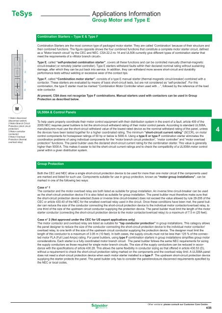
Combination Starters are the most common type of packaged motor starter. They are called ‘Combination’ because of their structure and<br />
their combined functions. The fi gure opposite shows the four combined functions that constitute a complete motor starter circuit, defined<br />
as a “Motor branch circuit” by the CEC and NEC. CSA 22.2 no 14 and UL508 currently give different types of combination starter that<br />
meet the requirements of a «Motor branch circuit».<br />
Type E, called “self-protected combination starter”, covers all these functions and can be controlled manually (thermal-magnetic<br />
circuit-breaker) or remotely (starter-controller). Type E starters withstand faults within their declared nominal rating without sustaining<br />
damage, after which they can be put back into service. In addition, they can withstand more severe short-circuit and durability<br />
performance tests without welding or excessive wear of the contact tips.<br />
Type F, called “Combination motor starter”, consists of a type E manual starter (thermal-magnetic circuit-breaker) combined with a<br />
contactor. These starters are evaluated by means of basic short-circuit tests, but are not considered as “self-protected”. For this<br />
combination, the type E starter must be marked “Combination Motor Controller when used with ...”, followed by the reference of the load<br />
side contactor.<br />
At present, CSA does not recognize Type F combinations. Manual starters used with contactors can be used in Group<br />
Protection as described below.<br />
M<br />
1 Motor disconnect<br />
(disconnect switch)<br />
2 Motor Branch Circuit<br />
Protection (short circuit<br />
protection)<br />
3 Motor controller<br />
(contactor)<br />
4 Motor Overload<br />
Protection (thermal<br />
overload relay)<br />
UL508A & Control Panels<br />
To help users properly coordinate their motor control equipment with their distribution system in the event of a fault, article 409 of the<br />
2005 NEC requires panel builders to list the short-circuit withstand rating of their motor control panels. According to standard UL508A,<br />
manufacturers must use the short-circuit withstand value of the lowest rated device as the nominal withstand rating of the panel, unless<br />
the devices have been tested together for a higher coordinated rating. The minimum “short-circuit current rating” (SCCR), on motor<br />
control components for horsepower ratings of 50 hp or below is 5000 A. Using a type E or type F combination starter eliminates the<br />
coordination problems of using individual components for the “motor branch circuit protection”, “motor controller” and “motor overload<br />
protection” functions. The panel builder uses the declared short-circuit current rating for the combination starter. This value is generally<br />
higher than 5000 A. This makes it easier to list the short-circuit current ratings and to check the compatibility of a UL508A motor control<br />
panel within a given distribution system.<br />
4<br />
Group Protection<br />
Both the CEC and NEC allow a single short-circuit protection device to be used for more than one motor circuit if the components used<br />
are marked and listed for such use. Components suitable for use in group protection, known as “motor group installations”, can be<br />
marked in one of the following two ways:<br />
Case n° 1<br />
The contactor and the motor overload relay are both listed as suitable for group installation. An inverse time circuit-breaker can be used<br />
as the short-circuit protection device if it is also listed as suitable for group installation. The panel builder must therefore make sure that<br />
the short-circuit protection device selected (fuses or inverse time circuit-breaker) does not exceed the value allowed by rule 28-206 of the<br />
CEC or article 430.40 of the NEC for the smallest overload relay used in the circuit. Once these conditions have been met, the panel builder<br />
can reduce the size of the conductor connecting the short-circuit protection device to the individual motor contactor/overload relay, to<br />
one third of the size of the upstream circuit conductor supplying the protection device. The panel builder must limit the length of the motor<br />
starter conductor (connecting the short-circuit protection device to the motor contactor/overload relay) to a maximum of 7.5 m (25 feet).<br />
Case n° 2 (Not approved under the CEC for US export applications only)<br />
The motor contactor and overload relay are listed as suitable for “tap conductor protection” in group installations. This category allows<br />
the panel designer to reduce the size of the conductor connecting the short-circuit protection device to the individual motor contactor/<br />
overload relay, to one tenth of the size of the upstream circuit conductor supplying the protection device. The designer must limit the<br />
length of this conductor to a maximum of 3.05 m (10 feet). In both cases, the supply circuits must not be less than 125 % of the connected<br />
motor FLA (Full Load Amps) rating. For panel builders, using type F combination starters in group installations simplifi es group motor<br />
considerations. Each starter is a fully coordinated motor branch circuit. The panel builder follows the same NEC requirements for sizing<br />
the supply conductors as those required for single motor branch circuits. The size of the supply conductors can be reduced in accordance<br />
with the specifi cations of article 430.28. This allows the same fl exibility in conductor sizing as that offered in article 430.53 (D),<br />
without a requirement to check the short-circuit protection rating marked on the components and the overload relay limit. A UL508A panel<br />
does not need a short-circuit protection device when each motor starter installed is a type F. The upstream short-circuit protection device<br />
supplying the starter protects the panel. The panel builder only has to consider the panel/enclosure disconnect requirements specified by<br />
the NEC or local codes.<br />
Other versions: Please consult our Customer Care Centre.<br />
35<br />
Other versions: please consult our Customer Care Centre.<br />
4/35