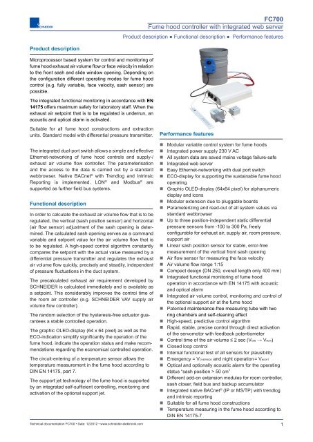
FC700 Fume hood controller with integrated web server - Schneider ...
FC700 Fume hood controller with integrated web server - Schneider ...
FC700 Fume hood controller with integrated web server - Schneider ...

Create successful ePaper yourself
Turn your PDF publications into a flip-book with our unique Google optimized e-Paper software.
<strong>FC700</strong><br />
<strong>Fume</strong> <strong>hood</strong> <strong>controller</strong> <strong>with</strong> <strong>integrated</strong> <strong>web</strong> <strong>server</strong><br />
Product description ● Functional description ● Performance features<br />
Product description<br />
Microprocessor based system for control and monitoring of<br />
fume <strong>hood</strong> exhaust air volume fl ow or face velocity in relation<br />
to the front sash and slide window opening. Depending on<br />
the confi guration different operating modes for fume <strong>hood</strong><br />
control (e.g. fully variable, face velocity, sash sensor) are<br />
possible.<br />
The <strong>integrated</strong> functional monitoring in accordance <strong>with</strong> EN<br />
14175 offers maximum safety for laboratory staff. When the<br />
exhaust air setpoint that is to be regulated is underrun, an<br />
acoustic and optical alarm is activated.<br />
Suitable for all fume <strong>hood</strong> constructions and extraction<br />
units. Standard model <strong>with</strong> differential pressure transmitter.<br />
The <strong>integrated</strong> dual-port switch allows a simple and effective<br />
Ethernet-networking of fume <strong>hood</strong> controls and supply-/<br />
exhaust air volume fl ow <strong>controller</strong>. The parameterisation<br />
and the access to the data is carried out by a standard<br />
<strong>web</strong>browser. Native BACnet ® <strong>with</strong> Trendlog and Intrinsic<br />
Reporting is implemented. LON ® and Modbus ® are<br />
supported as further fi eld bus systems.<br />
Functional description<br />
In order to calculate the exhaust air volume fl ow that is to be<br />
regulated, the vertical (sash position sensor) and horizontal<br />
(air fl ow sensor) adjustment of the sash opening is determined.<br />
The calculated sash opening serves as a command<br />
variable and setpoint value for the air volume fl ow that is<br />
to be regulated. A high-speed control algorithm constantly<br />
compares the setpoint <strong>with</strong> the actual value measured by a<br />
differential pressure transmitter and regulates the exhaust<br />
air volume fl ow quickly, precisely and steadily, independent<br />
of pressure fl uctuations in the duct system.<br />
The precalculated exhaust air requirement developed by<br />
SCHNEIDER is calculated immediately and is available as<br />
a setpoint. This considerably improves the control time of<br />
the room air <strong>controller</strong> (e.g. SCHNEIDER VAV supply air<br />
volume fl ow <strong>controller</strong>).<br />
The random selection of the hysteresis-free actuator guarantees<br />
a stable controlled operation.<br />
The graphic OLED-display (64 x 64 pixel) as well as the<br />
ECO-indication simplify signifi cantly the operation of the<br />
fume <strong>hood</strong>, indicate the operation status and make recommendations<br />
regarding the economical controlled operation.<br />
The circuit-entering of a temperature sensor allows the<br />
temperature measurement in the fume <strong>hood</strong> according to<br />
DIN EN 14175, part 7.<br />
The support jet technology of the fume <strong>hood</strong> is supported<br />
by an <strong>integrated</strong> self-suffi cient controlling, monitoring and<br />
activation of the optional support jet.<br />
Technical documentation <strong>FC700</strong> • Date: 12/2012 • www.schneider-elektronik.com<br />
Performance features<br />
• Modular variable control system for fume <strong>hood</strong>s<br />
• Integrated power supply 230 V AC<br />
• All system data are saved mains voltage failure-safe<br />
• Integrated <strong>web</strong> <strong>server</strong><br />
• Easy Ethernet-networking <strong>with</strong> dual port switch<br />
• ECO-display for supporting the sustainable fume <strong>hood</strong><br />
operating<br />
• Graphic OLED-display (64x64 pixel) for alphanumeric<br />
display and icons<br />
• Modular extension due to pluggable boards<br />
• Parameterizing and read-out of all system values via<br />
standard <strong>web</strong>browser<br />
• Up to three position-independent static differential<br />
pressure sensors from -100 to 300 Pa, freely<br />
configurable for exhaust air, supply air, room pressure,<br />
support air<br />
• Linear sash position sensor for stable, error-free<br />
measurement of the vertical front sash opening<br />
• Air fl ow sensor for measuring the face velocity<br />
• Air volume fl ow range 1:15<br />
• Compact design (DN 250, overall length only 400 mm)<br />
• Integrated functional monitoring of fume <strong>hood</strong><br />
operation in accordance <strong>with</strong> EN 14175 <strong>with</strong> acoustic<br />
and optical alarm<br />
• Integrated air volume control, monitoring and control of<br />
the optional support air at the fume <strong>hood</strong><br />
• Patented maintenance-free measuring tube <strong>with</strong> two<br />
ring chambers and self-cleaning effect<br />
• High-speed, predictive control algorithm<br />
• Rapid, stable, precise control through direct activation<br />
of the servomotor <strong>with</strong> feedback potentiometer<br />
• Control time of the air volume ≤ 2 sec (VMIN → VMAX)<br />
• Closed loop control<br />
• Internal functional test of all sensors for plausibility<br />
• Emergency = VOVERRIDE and night operation = VNIGHT<br />
• Optical and optionally acoustic alarm for the operating<br />
status “sash position > 50 cm”<br />
• Different add-on extension modules for room <strong>controller</strong>,<br />
sash closer, fi eld bus and backup accumulator<br />
• Integrated native BACnet ® (IP or MS/TP) <strong>with</strong> trendlog<br />
and intrinsic reporting<br />
• Suitable for all fume <strong>hood</strong> constructions<br />
• Temperature measuring in the fume <strong>hood</strong> according to<br />
DIN EN 14175-7<br />
1
<strong>FC700</strong><br />
<strong>Fume</strong> <strong>hood</strong> <strong>controller</strong> <strong>with</strong> <strong>integrated</strong> <strong>web</strong> <strong>server</strong><br />
Ordering code: <strong>Fume</strong> <strong>hood</strong> <strong>controller</strong><br />
Order code: <strong>Fume</strong> <strong>hood</strong> <strong>controller</strong> <strong>with</strong> <strong>integrated</strong> <strong>web</strong> <strong>server</strong><br />
<strong>FC700</strong> - V - A - BIP - 0700 - 3 - 0<br />
-<br />
T<br />
2 - Supply voltage<br />
Type<br />
Control type<br />
Fully variable air volume<br />
Face velocity <strong>with</strong> VMIN and VMAX limitation<br />
Constant face velocity<br />
Position sensor dependent air volume<br />
control<br />
Constant air volume control<br />
(1/2/3-step)<br />
Housing<br />
Standard<br />
Client-specifi c designs<br />
Interface to BMS/field bus module<br />
Internal networking TCP/IP, Ethernet<br />
Analogue/digital (extension module EM10)<br />
Native BACnet ® , TCP/IP, Ethernet<br />
Native BACnet ® , MS/TP, RS485<br />
V<br />
FP<br />
F<br />
W<br />
LON, FTT-10A (Extension module EMLON)<br />
Modbus, IP<br />
Modbus, RS485<br />
K<br />
A<br />
G...Z<br />
IP<br />
AD<br />
BIP<br />
BM<br />
L<br />
MIP<br />
M<br />
0700<br />
...<br />
0999<br />
1000<br />
...<br />
9999<br />
0 24 V AC external, 30 VA<br />
T Internal power supply 230 VAC/24 VAC/30 VA<br />
Emergency power pack 12 V/1,2 Ah<br />
0 <strong>with</strong>out<br />
N<br />
<strong>with</strong><br />
Function display cable length<br />
3 3 m<br />
5 5 m<br />
Function display type<br />
various SCHNEIDER standard models<br />
(see data sheet: functional displays and<br />
control panels, standard versions)<br />
client-specific designs<br />
(see data sheet: functional displays and<br />
control panels, standard versions)<br />
Static differential pressure sensors -100...300 Pa<br />
1 1 sensor, free confi gurable: exhaust, supply, support, room pressure<br />
2 2 sensors, free confi gurable: exhaust, supply, support, room pressure<br />
3 3 sensors, free confi gurable: exhaust, supply, support, room pressure<br />
Control type<br />
V = fully variable<br />
FP = face velocity <strong>with</strong><br />
VMIN and VMAX limitation<br />
F = face velocity<br />
W = position sensor<br />
K = constant (1 step<br />
up to 3 steps)<br />
Sensors included <strong>with</strong> delivery and customer<br />
supplied limit switches<br />
position sensor, air fl ow sensor, differential pressure<br />
sensor<br />
air fl ow sensor, differential pressure sensor<br />
air fl ow sensor<br />
sash position sensor, differential pressure sensor<br />
differential pressure sensor and 1 limit switch (2 step<br />
control) or 2 limit switches (3 step control). Limit<br />
switches customer supplied<br />
Important:<br />
Order MD-measuring system <strong>with</strong><br />
damper and actuator as well. Order<br />
optional extension modules as well.<br />
Ordering example: fume <strong>hood</strong> <strong>controller</strong> <strong>FC700</strong><br />
fully variable air volume control, housing = standard, <strong>with</strong> BACnet ® /IP, 2 relays, <strong>with</strong> 2 static differential pressure sensors,<br />
function display and control panel type = 0700 <strong>with</strong> 3 m cable, <strong>with</strong>out emergency power pack, <strong>with</strong> internal transformer<br />
(power supply, 230 V AC).<br />
Make: SCHNEIDER<br />
Type: <strong>FC700</strong>-V-A-BIP-2-0700-3-0-T<br />
2<br />
Technical documentation <strong>FC700</strong> • Date: 12/2012 • www.schneider-elektronik.com
<strong>FC700</strong><br />
<strong>Fume</strong> <strong>hood</strong> <strong>controller</strong> <strong>with</strong> <strong>integrated</strong> <strong>web</strong> <strong>server</strong><br />
Ordering code: Measuring system <strong>with</strong> damper and fast actuator<br />
Order code: Measuring system <strong>with</strong> damper and high-speed actuator, round design<br />
MD - 250 - P - 0 - 0 - 0 - MM -<br />
1<br />
Measuring system<br />
Maintenance-free measuring<br />
tube<br />
Venturi nozzle<br />
Measuring nozzle<br />
Measuring cross <strong>with</strong> add.<br />
baffl e<br />
Material<br />
Housing<br />
MD<br />
VD<br />
DD<br />
KD<br />
Nominal diameter DN [mm]<br />
110, 125, 160, 200, 250, 315 110<br />
...<br />
315<br />
Versions<br />
Polypropylene (PPs), fi re MD, VD<br />
retardant<br />
P<br />
PPs-el (electrically conductive)<br />
MD, VD Pel<br />
Polyvinyl chloride (PVC) MD, VD PV<br />
Galvanised steel MD, DD, KD S<br />
Stainless steel 1.4301 MD, DD, KD V2<br />
(V2A)<br />
Stainless steel 1.4571<br />
(V4A)<br />
MD, DD, KD V4<br />
Actuator type<br />
1 SCHNEIDER standard 12 V, 3 s for 90 °<br />
2 Analogue linear drive 24 V, 5 s for 90 °<br />
Air inflow Air outflow<br />
Pipe connections<br />
Remarks<br />
MM socket socket only PPs, PPs-el<br />
FF fl ange fl ange PPs, PPs-el, steel, stainless<br />
steel<br />
MF socket fl ange only PPs, PPs-el<br />
FM fl ange socket only PPs, PPs-el<br />
RR pipe pipe PPs, PPs-el, steel, stainless<br />
steel<br />
Insulating shell<br />
0 <strong>with</strong>out<br />
D<br />
<strong>with</strong> insulating shell<br />
Rubber lip seal<br />
0 <strong>with</strong>out<br />
G<br />
<strong>with</strong> rubber lip seal (only steel and stainless steel)<br />
Damper blade seal<br />
0 <strong>with</strong>out (standard version in PPs)<br />
K<br />
<strong>with</strong> (standard version in steel and stainless steel)<br />
Important:<br />
Air volumes and dimensions at page 25.<br />
Order fume <strong>hood</strong> <strong>controller</strong> <strong>FC700</strong> as well.<br />
Note:<br />
For measuring systems VD, DD or KD ensure adequate inflow and outfl ow distances (> 1xD) (see data sheet VAV500/VAV700).<br />
Ordering example: Round damper <strong>with</strong> maintenance-free measuring system and actuator<br />
Maintenance-free measuring system <strong>with</strong> damper, DN 250, PPs, <strong>with</strong>out damper blade seal, <strong>with</strong>out insulation shell,<br />
socket/socket, fast actuator 3 s for 90 ° (fast direct drive SCHNEIDER).<br />
Make: SCHNEIDER<br />
Type: MD-250-P-0-0-0-MM-1<br />
Technical documentation <strong>FC700</strong> • Date: 12/2012 • www.schneider-elektronik.com<br />
3
<strong>FC700</strong><br />
<strong>Fume</strong> <strong>hood</strong> <strong>controller</strong> <strong>with</strong> <strong>integrated</strong> <strong>web</strong> <strong>server</strong><br />
Ordering code: Extension modules for fume <strong>hood</strong> <strong>controller</strong><br />
Order code:<br />
Extension modules<br />
EM10<br />
--<br />
--<br />
--<br />
--<br />
EMSC<br />
--<br />
Extension modules<br />
Bemerkung/Lieferumfang<br />
EM10<br />
2 analogue inputs, 2 analogue outputs, Suitable for conventional connection to the building<br />
2 digital inputs, 2 relay outputs<br />
management system (BMS)<br />
EM20 4 analogue inputs, 4 analogue outputs General applications, actuator and valve activation<br />
EM30 6 relay outputs General applications, actuator and valve activation<br />
EM40 4 Triac outputs For valve activation, heating/cooling<br />
EM50<br />
Charging circuit <strong>with</strong> discharge circuit for With battery backup 12 V DC/1,2 Ah in its own housing<br />
battery backup 12 V DC<br />
EMSC Automatic sash closing module wit PIR, light barrier and drive unit<br />
EMLON LON, FTT10-A Field bus module<br />
Important:<br />
Maximal 4 extension modules are<br />
pluggable (4 free slots in the <strong>FC700</strong>).<br />
Order example: Extension module<br />
1 x EM10 for conventional connection to the building management system <strong>with</strong> 2 analogue inputs, 2 analogue outputs,<br />
2 digital inputs, 2 relay outputs, 1 x EMSC automatic sash closing module <strong>with</strong> equipment.<br />
Make: SCHNEIDER<br />
Type: EM10, EMSC<br />
4<br />
Technical documentation <strong>FC700</strong> • Date: 12/2012 • www.schneider-elektronik.com
m³/h<br />
Day<br />
<strong>FC700</strong><br />
<strong>Fume</strong> <strong>hood</strong> <strong>controller</strong> <strong>with</strong> <strong>integrated</strong> <strong>web</strong> <strong>server</strong><br />
Function description<br />
Block diagram<br />
Picture 1 shows the block diagram and the piping of the<br />
static differential pressure sensor <strong>with</strong> a maintenance-free<br />
measuring system.<br />
All plugs of the sensors and actuators are pre-assembled<br />
and directly pluggable on the outside of the <strong>FC700</strong>-housing.<br />
That means an immense reduction of the assembly time<br />
and a simplifi cation of the commissioning. The high speed<br />
hysteresis-free actuator is operated in the proven direct<br />
drive mode and guarantees high control accuracy, highest<br />
durability and lifetime.<br />
The pre-assembled CAT6/CAT7-cable for the Ethernetnetworking<br />
will be plugged in the dual port switch and the<br />
system is ready for commissioning.<br />
Damper<br />
Maintenance-free<br />
measuring system<br />
<strong>Fume</strong> <strong>hood</strong><br />
Supply air<br />
Exhaust air<br />
-<br />
+<br />
M<br />
Feedback<br />
potentiometer<br />
Actuator<br />
Air velocity<br />
sensor<br />
Sash<br />
position<br />
sensor<br />
p<br />
Static differential<br />
pressure transmitter<br />
485<br />
OK<br />
LOW<br />
ECO<br />
Back up<br />
accumulator<br />
Controller<br />
<strong>FC700</strong><br />
Monitoring in<br />
accordance<br />
<strong>with</strong> EN 14175<br />
230 VAC main<br />
Day/Night operation<br />
Digital input/output<br />
Analogue input/output 0...10V DC<br />
BACnet / LON-Network<br />
Ethernet/IP<br />
Laptop<br />
Web browser operation<br />
The internal <strong>web</strong> sites of the <strong>integrated</strong> <strong>web</strong> <strong>server</strong> can be<br />
visualised via a standard <strong>web</strong> browser. Adjustments and<br />
parameter can be simply changed. By using a standard <strong>web</strong><br />
browser project-dependent fi les are no longer necessary to<br />
access the central building control system worldwide and<br />
at any time. The internal visualisation software VIS7000<br />
reduces signifi cantly the system costs (data points) on the<br />
building management system level and can assume the<br />
building management functions if necessary.<br />
Native BACnet ® -IP<br />
The building management system is provided <strong>with</strong> a<br />
multitude of data and therefore allows an optimsed<br />
requirement planning and process control. Native BACnet ®<br />
(IP or MS/TP) guarantees a fast, simple and direct<br />
connection to the building management system <strong>with</strong>out<br />
additional gateways. Our own BACnet ® stack developed by<br />
SCHNEIDER guarantees maximum fl exibility. We support<br />
the read-out and storage of trendlog data as well as intrinsic<br />
reporting.<br />
Simple wiring and fast commissioning<br />
A simple and fast wiring and commissioning are the main<br />
parameters to reduce signifi cantly the installation and<br />
assembly costs. The dual port switch <strong>integrated</strong> on the<br />
CPU-board allows an easy daisy chain wiring <strong>with</strong> preassembled<br />
cables.<br />
Picture 1: Block diagram fume <strong>hood</strong> <strong>controller</strong> <strong>FC700</strong><br />
Picture2: Daisy chain wiring<br />
Networking<br />
Room<br />
supply air<br />
Controller<br />
Controller<br />
Controller<br />
Controller<br />
Room<br />
exhaust air<br />
The networking offers maximum fl exibility and safety. The<br />
connection to the building management system offers the<br />
complete ventilation control and monitoring of all laboratories.<br />
A fl exible network-adjustment is simply realised by modular<br />
extension cards. Besides the already <strong>integrated</strong> native<br />
BACnet ® (IP or MS/TP) and Modbus ® (IP or MS/TP) LON ® is<br />
also available. The fi eld bus boards can be retrofi tted simply<br />
and at any time for all SCHNEIDER LabSystem products.<br />
Internet technology <strong>with</strong> <strong>integrated</strong> <strong>web</strong> <strong>server</strong><br />
The <strong>FC700</strong> possesses an <strong>integrated</strong> <strong>web</strong> <strong>server</strong> for a<br />
simple data exchange and to improve the system security<br />
and it communicates via the Internet protocol TCP/IP.<br />
The operation and parameterisation is carried out by<br />
a laptop <strong>with</strong> a standard <strong>web</strong> browser. For this reason a<br />
simple circuit-entering into multivendor capable building<br />
management systems is guaranteed and the system is<br />
therefore prepared for all future applications.<br />
VAV700<br />
<strong>FC700</strong><br />
<strong>FC700</strong><br />
<strong>FC700</strong><br />
<strong>FC700</strong><br />
The wiring can be executed radially as well.<br />
VAV700<br />
The commissioning, confi guration, diagnosis and<br />
visualisation of all system data (e. g. control time, damper<br />
position and setpoint settings) occur centrally through the<br />
network by a control unit via PC <strong>with</strong> standard <strong>web</strong> browser<br />
or decentrally via infrared interface of the graphic indication<br />
and operation panel.<br />
Technical documentation <strong>FC700</strong> • Date: 12/2012 • www.schneider-elektronik.com<br />
5
<strong>FC700</strong><br />
<strong>Fume</strong> <strong>hood</strong> <strong>controller</strong> <strong>with</strong> <strong>integrated</strong> <strong>web</strong> <strong>server</strong><br />
Function description<br />
Therefore the connection of the bus cable is omitted. All<br />
standard cables, e. g. sensor cable, actuator cable, etc. are<br />
pre-assembled and externally pluggable.<br />
Building management system<br />
The building management system balances the air requirement<br />
of the complete building and can check the plausibility<br />
of all room <strong>controller</strong>s. Day/night switching, visualisation<br />
of status and fault reports as well as actual values can be<br />
easily <strong>integrated</strong>. Remote maintenance and remote fault diagnostics<br />
as well as an air consumption measuring related<br />
to the laboratory or fume <strong>hood</strong> <strong>with</strong> individual accounting is<br />
also possible.<br />
Graphic functional display and operation panel<br />
Due to the graphic OLED display (64 x 64 pixel) of the function<br />
indication all signifi cant operation and status information<br />
are directly readable. Volume fl ow, infl ow velocity, fault<br />
and operation reports are shown immediately in clear words<br />
and status reports are illustrated by graphic icons.<br />
Picture 3: Graphic OLED display<br />
• Audible and visual alarm (red LED) for too low exhaust<br />
air/supply air<br />
• Visual indication (green LED) for suffi cient exhaust air/<br />
supply air<br />
• RESET-key to confi rm the audible alarm<br />
• Yellow fl ashing LED as a visual alarm for the operating<br />
condition „sash position > 50 cm“<br />
• Infrared interface for decentral parameterisation via<br />
laptop (software PC2500) <strong>with</strong> IR adapter<br />
Options:<br />
• Button <strong>controller</strong> ON/OFF <strong>with</strong> LED status indication<br />
• Button light ON/OFF (fume <strong>hood</strong> interior light)<br />
• Button VMAX <strong>with</strong> LED status indication for emergency<br />
power supply (override)<br />
• Button VMIN <strong>with</strong> LED status indication for night setback<br />
(reduced operation)<br />
• Button UP/DOWN for automatic sash locking system<br />
(<strong>with</strong> extension module EMSC)<br />
Energy efficiency indication (ECO)<br />
The energy effi ciency indication (ECO) of the controlled<br />
fume <strong>hood</strong> is a global innovation. The energy consumption<br />
of the individual operating mode is established by the<br />
average determination compared to other linked fume<br />
<strong>hood</strong>s in the laboratory building and shown on the ECO<br />
indication. Parameter like busy time, sash and cross slide<br />
opening period as well as fast and complete closing of the<br />
sash are included in this evaluation. The ECO indication<br />
provides information to the user how energy-consciously the<br />
fume <strong>hood</strong> is operated and promotes a rethinking towards a<br />
conscious and economical handling of the energy.<br />
Picture 4: Energy effi ciency indication (ECO)<br />
Different variants of the function and operation panel are<br />
available as a wall mounted housing or as an <strong>integrated</strong><br />
version (please refer to the data sheet „function displays<br />
standard versions).<br />
Custom made constructions can be realised quickly and<br />
cost-effectively on demand.<br />
Functions:<br />
• Graphic OLED display (64 x 64 Pixel) for numeric<br />
indication of the volume fl ow or the infl ow velocity as<br />
well as alphanumeric indication of operation and status<br />
reports<br />
• Energy effi ciency indication (ECO) as a tricoloured<br />
bargraph<br />
6<br />
Technical documentation <strong>FC700</strong> • Date: 12/2012 • www.schneider-elektronik.com
<strong>FC700</strong><br />
<strong>Fume</strong> <strong>hood</strong> <strong>controller</strong> <strong>with</strong> <strong>integrated</strong> <strong>web</strong> <strong>server</strong><br />
Funktionsbeschreibung<br />
Integrated support jet controlling and regulation<br />
The support jet technology improves the blowout behaviour<br />
in case of lower exhaust air fl ows if the construction of the<br />
fume <strong>hood</strong> is applicable. That means a fume <strong>hood</strong> <strong>with</strong><br />
support jet is more energy-effi cient. The <strong>integrated</strong> support<br />
jet activation controls, regulates and monitors the support<br />
jet fan of the fume <strong>hood</strong>. You can choose a simple on/off<strong>controller</strong><br />
or a <strong>controller</strong> (0-10 V DC) depending on the<br />
sash.<br />
An own static differential pressure sensor is used to monitor<br />
the faultlessly functioning support jet fan by constant<br />
monitoring the support jet volume fl ow. In case of alarm<br />
(volume fl ow is too low) it will be indicated clearly on the<br />
graphic display and the sash will be closed automatically<br />
(<strong>with</strong> extension module EMSC). As an option the exhaust<br />
air fl ow can be automatically raised to a safe range.<br />
Integrated sash closing system<br />
The <strong>FC700</strong> <strong>controller</strong> can simultaneously be used as an<br />
automatic sash closing system via the extension card EMSC<br />
and a drive unit to be mounted at the fume <strong>hood</strong>. This<br />
includes a passive infrared sensor for presence detection of<br />
the user and a light barrier for obstacle detection during the<br />
automatic closing.<br />
This combination of control and closing system offers a<br />
cost-effective compact function unit <strong>with</strong> all advantages of<br />
the networked technology. The sash position is visualisable<br />
at any time via the building management system and e. g.<br />
in case of fi re and smoke scenarios the sash can be closed<br />
immediately and automatically.<br />
Picture 6: Drive unit closing system<br />
A fl ow monitoring (maximum and minimum) of the connected<br />
support jet fans is possible as well.<br />
Up to three position independent sensors<br />
For <strong>FC700</strong> up to three position independent static sensors<br />
(-100-300 Pa) are available as an option and can be freely<br />
confi gured. Because of the high sensibility and resolution a<br />
volume fl ow range of 1:15 can be adjusted smoothly.<br />
The function classifi cations exhaust air, supply air, support<br />
jet and room pressure to the static differential pressure<br />
sensors are freely configurable. Therefore the <strong>controller</strong> can<br />
be simply and fl exibly adjusted to all kind of applications. All<br />
data and measuring values are available at any time by the<br />
connected network.<br />
Picture 5: Sensor board <strong>with</strong> three static differential<br />
pressure sensors<br />
Technical documentation <strong>FC700</strong> • Date: 12/2012 • www.schneider-elektronik.com<br />
7
<strong>FC700</strong><br />
<strong>Fume</strong> <strong>hood</strong> <strong>controller</strong> <strong>with</strong> <strong>integrated</strong> <strong>web</strong> <strong>server</strong><br />
Function description<br />
Extension modules<br />
The motherboard of the <strong>FC700</strong> <strong>controller</strong> possesses up to<br />
four free extension slots. The <strong>controller</strong> can be arbitrarily<br />
extended to further functions besides the sash closing<br />
function (extension module EMSC).<br />
Custom made extension modules for special measuring,<br />
controlling and regulation functions can be easily and costeffectively<br />
developed.<br />
The following extension modules are available:<br />
Extension<br />
module<br />
EM10<br />
EM20<br />
EM30<br />
EM40<br />
EMNA<br />
EMSC<br />
EMLON<br />
Function<br />
2 analogue inputs, 2 analogue outputs,<br />
2 digital inputs, 2 relay outputs<br />
4 analogue inputs, 4 analogue outputs<br />
6 relay outputs<br />
4 Triac outputs for fan regulation,<br />
heating/cooling<br />
Charging circuit <strong>with</strong> discharge circuit<br />
for battery backup 12 V DC<br />
Automatic sash closing module<br />
Field bus module, LON ® , FTT10-A<br />
Temperature monitoring according to DIN 14175-7<br />
in the fume <strong>hood</strong>’s interior<br />
Thermal loads are measured conforming to standards<br />
according to DIN EN 14175-7, alarmed via the graphic<br />
OLED-display and safely conducted by increasing the<br />
exhaust air volume fl ow.<br />
The temperature sensor PT1000 <strong>with</strong> stainless steel<br />
measuring sleeve specifi cally mounted inside the fume<br />
<strong>hood</strong> is therefore directly connected <strong>with</strong> the input terminal<br />
of <strong>FC700</strong>.<br />
Heating and cooling of the laboratory<br />
The heating and cooling of laboratories via appropriate<br />
heating and cooling registers can also be executed by <strong>FC700</strong>.<br />
The appropriate analogue and Triac outputs to regulate the<br />
heating and cooling valves will be made availabe by the<br />
extension modules EM10 to EM40. The power supply of the<br />
valves is provided by <strong>FC700</strong> as well and the independent<br />
closed loop which is already implemented by default.<br />
All measured room temperatures are available as actual<br />
value via network.<br />
Picture7: Four free slots<br />
Picture 8: Valve regulation<br />
M<br />
Dehumidify<br />
FUME HOOD<br />
FC<br />
EM20<br />
4 x Analog input<br />
4 x Analog output<br />
M<br />
M<br />
M<br />
Humidify<br />
Cooling<br />
Heating<br />
-<br />
+<br />
Slot 6 (on the right side) is always equipped <strong>with</strong> the sensor<br />
board and slot 5 <strong>with</strong> the CPU board. The slots 1 to 4 (left to<br />
right) can be freely equipped <strong>with</strong> the above listed extension<br />
modules.<br />
Project planning<br />
The project planning and parameterisation software<br />
PRO7000 is compatible to Windows and is used for a<br />
simple and fast commissioning. Parameterisation of<br />
devices can be executed from a central point for the<br />
entire room respectively the entire building. All data of<br />
the connected devices <strong>with</strong> <strong>integrated</strong> <strong>web</strong> <strong>server</strong> by<br />
SCHNEIDER can be indicated via standard <strong>web</strong> browser<br />
and entries can be done password protected.<br />
8<br />
Technical documentation <strong>FC700</strong> • Date: 12/2012 • www.schneider-elektronik.com
<strong>FC700</strong><br />
<strong>Fume</strong> <strong>hood</strong> <strong>controller</strong> <strong>with</strong> <strong>integrated</strong> <strong>web</strong> <strong>server</strong><br />
Function description<br />
Visualisation<br />
All relevant data is available for the building management<br />
system (BMD) via the network and can be used for facility<br />
management functions. A better planning and utilisation<br />
of the ressources as well as a reduction of energy and<br />
operational costs are the significant characteristics.<br />
Laboratory occupation plans, night setback and individual<br />
accounting of the air consumption data, energy-efficient<br />
operation as well as the safety improvement via remote<br />
maintenance and remote diagnosis of the fume <strong>hood</strong><br />
<strong>controller</strong> and the volume flow <strong>controller</strong> for room supply<br />
air and room exhaust air are the outstanding advantages<br />
of the network technology <strong>with</strong> an <strong>integrated</strong> building<br />
management system (BMS).<br />
The visualisation software module VIS7000 is the<br />
reasonable extension of PRO7000 and allows the simple<br />
creation of room graphics and a free alignment of single<br />
devices (e. g. fume <strong>hood</strong>, volume flow <strong>controller</strong>, etc.) in the<br />
room. This is a cost-efficient integral system solution <strong>with</strong><br />
functions of the building management system.<br />
The touchscreen <strong>controller</strong> PAD7000 developed by<br />
SCHNEIDER is especially adjusted to the requirements<br />
of the laboratory ventilation system and adopts the<br />
functionalities of the building management system. Special<br />
templates are a freely disposable. Trendlog and intrinsic<br />
reporting are implemented as well. Networking via BACnet ®<br />
(IP or MS/TP) and LON ® is supported.<br />
Picture 9: Touchscreen <strong>controller</strong> PAD7000<br />
Technical documentation <strong>FC700</strong> • Date: 12/2012 • www.schneider-elektronik.com<br />
9
<strong>FC700</strong><br />
<strong>Fume</strong> <strong>hood</strong> <strong>controller</strong> <strong>with</strong> <strong>integrated</strong> <strong>web</strong> <strong>server</strong><br />
Controller operating modes<br />
<strong>Fume</strong> <strong>hood</strong> <strong>controller</strong> operating modes<br />
Depending on the configuration and the area of application,<br />
various modes of operation are possible. The following<br />
control types are implemented:<br />
Controller type<br />
<strong>FC700</strong>-V<br />
<strong>FC700</strong>-FP<br />
<strong>FC700</strong>-F<br />
<strong>FC700</strong>-W<br />
<strong>FC700</strong>-K<br />
Controller operating mode<br />
Fully variable air volume fl ow control<br />
Constant face velocity control <strong>with</strong><br />
limitation to VMIN and VMAX<br />
Constant face velocity control<br />
Sash sensor air volume control<br />
Constant air volume fl ow control<br />
(1-/2-/3-steps)<br />
Face velocity v [m/sec]<br />
0,8<br />
V3=VMAX<br />
0,6<br />
V2=V50cm<br />
0,4<br />
0,2<br />
V1=VMIN<br />
SHUT<br />
Sash position<br />
OPEN<br />
= Face velocity<br />
= Air volume<br />
Figure 10: Fully variable air volume fl ow control<br />
600<br />
450<br />
300<br />
150<br />
Air volume V [m 3 /h]<br />
The listing of the <strong>controller</strong> operating modes describes<br />
from top to down the distribution in the market, e.g. the fully<br />
variable air volume fl ow control <strong>FC700</strong>-V has the highest<br />
market share.<br />
Fully variable air volume flow control<br />
In terms of energy effi ciency, this mode of operation is the<br />
most expedient and the best method of fume <strong>hood</strong> control.<br />
A very fast and yet stable control algorithm is the most<br />
notable technical feature of this control mode.<br />
The FC500-V <strong>controller</strong> seamlessly regulates the exhaust<br />
air volume fl ow in relation to the fume <strong>hood</strong> sash position.<br />
The fume <strong>hood</strong> exhaust air fl ow is regulated either by a<br />
motor-driven damper (in <strong>hood</strong>s that are connected to a<br />
manifold air system) or by an <strong>integrated</strong> exhaust air motor<br />
<strong>with</strong> a frequency inverter.<br />
Pressure fl uctuations in the duct system are regulated<br />
quickly, precisely and steadily. The exhaust air volume<br />
fl ows V1, V2 and V3 are freely programmable and defi ne<br />
the vertices of the control curve.<br />
V1 = V MIN<br />
When the sash is closed (SHUT) regulation takes place<br />
according to a programmable V1 exhaust air fl ow (minimum<br />
exhaust air fl ow). The containment-safety of the fume <strong>hood</strong><br />
is guaranteed at all times while air consumption remains at<br />
a minimum.<br />
V2 = V 50cm<br />
The second point of the volume air fl ow is V2, which<br />
represents the exhaust air volume fl ow when the sash is<br />
partly open (e.g. sash = 50 cm). Seamless regulation of the<br />
required exhaust air volume fl ow takes place independent<br />
of the sash opening between V1 and V2 (SHUT ≤ sash ≤ 50<br />
cm). The vertices V1, V2 and V3 are freely programmable<br />
and can be assigned to any sash opening, e.g. V2 at sash<br />
= 50 cm.<br />
V3 = V MAX<br />
The third point of the exhaust air volume fl ow is V3, which<br />
represents the exhaust air volume fl ow when the sash is<br />
fully open (e.g. sash = 90 cm). Seamless regulation of the<br />
required exhaust air volume fl ow takes place between V2<br />
and V3 (50 cm ≤ sash ≤ 90 cm) and is dependent on the<br />
sash opening.<br />
Constant face velocity control<br />
The <strong>FC700</strong>-FP/<strong>FC700</strong>-F regulates at a constant face<br />
velocity (e.g. v = 0,3...0,5 m/s), independent of the sash<br />
position. Here the air fl ow sensor AFS100 is used. A fl ow<br />
measurement (<strong>FC700</strong>-FP) is mandatory.<br />
The exhaust air volume fl ow is changed in relation to the<br />
fume <strong>hood</strong> sash position so that the face velocity remains<br />
constant. The fume <strong>hood</strong> exhaust air volume fl ow is regulated<br />
either by a motor-driven damper (in <strong>hood</strong>s connected to a<br />
central exhaust air system) or by an <strong>integrated</strong> exhaust air<br />
motor <strong>with</strong> a frequency inverter.<br />
Pressure fl uctuations in the duct system are regulated<br />
quickly, precisely and steadily. The face velocity v and<br />
additional <strong>with</strong> <strong>FC700</strong>-FP the exhaust air volume fl ows V MIN<br />
und V MAX<br />
are freely programmable.<br />
Air volume flow limitation V MIN<br />
and V MAX<br />
For operator safety, a minimum exhaust airfl ow V MIN<br />
is not<br />
undercut.<br />
When the sash is opened, the face velocity is reduced v <<br />
0,3 m/sec. When the safe exhaust air volume fl ow V MAX<br />
for<br />
the specifi c fume <strong>hood</strong> is reached, this value is constantly<br />
regulated. Thus the fume <strong>hood</strong> is <strong>with</strong>in the safe range<br />
and defi nitely containment-safe. The restriction of the<br />
exhaust air volume fl ow to V MAX<br />
ensures an energy saving<br />
effect and guarantees maximum safety for the laboratory<br />
staff. The load on the ventilation system is only as high<br />
as is absolutely necessary for the operating status of the<br />
particular fume <strong>hood</strong>.<br />
10<br />
Technical documentation <strong>FC700</strong> • Date: 12/2012 • www.schneider-elektronik.com
<strong>FC700</strong><br />
<strong>Fume</strong> <strong>hood</strong> <strong>controller</strong> <strong>with</strong> <strong>integrated</strong> <strong>web</strong> <strong>server</strong><br />
Controller operating modes<br />
Constant air volume flow control 1/2/3-steps<br />
Face velocity v [m/sec]<br />
0,8<br />
0,6<br />
0,4<br />
0,2<br />
VMIN<br />
SHUT<br />
= Face velocity<br />
= Air volume<br />
Sash position<br />
VMAX<br />
OPEN<br />
600<br />
450<br />
300<br />
150<br />
Air volume V [m 3 /h]<br />
The <strong>FC700</strong>-K <strong>controller</strong> regulates the exhaust air volume<br />
fl ow in relation to the sash position of the fume <strong>hood</strong>. The<br />
fume <strong>hood</strong> exhaust air is regulated either by a motor-driven<br />
damper (for <strong>hood</strong>s that are connected to a central exhaust<br />
air system) or by an <strong>integrated</strong> exhaust air motor <strong>with</strong> a<br />
frequency inverter. This regulation mode is next to the<br />
<strong>FC700</strong>-F the energetically worst solution.<br />
Pressure fl uctuations in the duct system are regulated<br />
quickly, precisely and steadily. The exhaust air volume fl ows<br />
V1, V2 and V3 are freely programmable.<br />
Figure 11: Constant face velocity control <strong>with</strong> air volume<br />
fl ow limitation V MIN<br />
and V MAX<br />
Air flow sensor<br />
With the air fl ow sensor developed by SCHNEIDER a change<br />
in position of the sash and/or slide window is automatically<br />
detected and <strong>integrated</strong> in the control algorithm.<br />
Sash position dependent air volume flow control<br />
In fume <strong>hood</strong>s <strong>with</strong>out a slide window, only one sash position<br />
sensor SPS100 is needed for an exact measurement of the<br />
vertical sash position.<br />
The specifi cation of setpoints by the sash position sensor<br />
enables stable, fast and accurate control. If turbulent and<br />
indefi nable air fl ows are present in the laboratory that may<br />
affect the measuring accuracy and stability of the air fl ow<br />
sensor, a sash position sensor is always a better choice<br />
than a fl ow sensor.<br />
The sash position measured by the sash position sensor is<br />
the setpoint for the <strong>FC700</strong>-W <strong>controller</strong>, which calculates<br />
the required exhaust air volume fl ow and and regulates it<br />
as needed. Volume fl ow is always linear in relation to the<br />
position sensor.<br />
1 step constant air volume flow control<br />
In 1 step constant <strong>controller</strong>s the exhaust air volume fl ow<br />
is constantly regulated at V1, independent of the sash<br />
position.<br />
2 step constant air volume flow control<br />
A 2 step constant <strong>controller</strong> regulates the exhaust air<br />
volume fl ow at V1 (sash = SHUT) or V2 (sash = NOT<br />
SHUT), depending on the sash position.<br />
The sash position (SHUT) is recognised by a limit switch. It<br />
is also possible to switch to reduced operating mode (nighttime<br />
operation and work-free time) manually or via a remote<br />
control input.<br />
3 step constant air volume flow control<br />
A 3 step constant <strong>controller</strong> regulates the exhaust air volume<br />
fl ow at V1 (sash = SHUT), V2 (sash < 50 cm OPEN) and<br />
V3 (sash > 50 cm OPEN), depending on the sash position.<br />
The sash positions (SHUT and > 50 cm) are both signalled<br />
by a limit switch. Switching to night-time operation is also<br />
possible.<br />
If the fume <strong>hood</strong> has a slide window, the slide window<br />
position (SHUT) must also be determined and in the 2 step<br />
or 3 step operating mode allowance must be made for the<br />
slide window position so that the exhaust air volume fl ow<br />
is increased accordingly when the slide window is opened.<br />
0,8<br />
V2=V3=VMAX<br />
600<br />
Face velocity v [m/sec]<br />
0,6<br />
0,4<br />
0,2<br />
V1=VMIN<br />
SHUT<br />
Sash position<br />
OPEN<br />
450<br />
300<br />
150<br />
Air volume V [m 3 /h]<br />
Face velocity v [m/sec]<br />
0,8<br />
0,6<br />
0,4<br />
0,2<br />
V1<br />
V2<br />
V3<br />
600<br />
450<br />
300<br />
150<br />
Air volume V [m 3 /h]<br />
= Face velocity<br />
= Air volume<br />
SHUT<br />
Sash position<br />
= Face velocity<br />
OPEN<br />
= Air volume<br />
Figure 12: Linear sash position air volume fl ow control<br />
Figure 13: 3-step constant air volume fl ow control<br />
Technical documentation <strong>FC700</strong> • Date: 12/2012 • www.schneider-elektronik.com<br />
11
<strong>FC700</strong><br />
<strong>Fume</strong> <strong>hood</strong> <strong>controller</strong> <strong>with</strong> <strong>integrated</strong> <strong>web</strong> <strong>server</strong><br />
Controller operating modes<br />
Fast upward regulation and slow downward<br />
regulation<br />
In all operating modes regulation is always upwards and at<br />
maximum velocity, i.e. when the front sash or slide window<br />
is opened, the calculated required volume fl ow follows and<br />
is increased <strong>with</strong>out delay.<br />
When the front sash or slide window is closed, downwards<br />
regulation can be done at adjustable speed of 2 - 24 s.<br />
Slow downwards regulation has the advantage that there<br />
is suffi cient time for the required room supply air and the<br />
laboratory always remains in a state of negative pressure in<br />
all operating conditions.<br />
Slow downwards regulation of the volume fl ow increases<br />
work safety for the laboaratory staff and eliminates the<br />
tendency towards oscillation of the entire control system.<br />
Plausibility check <strong>with</strong> three different sensors<br />
The <strong>FC700</strong> <strong>controller</strong> uses three different sensors (sash<br />
position sensor SPS100, static differential pressure<br />
transmitter and air fl ow sensor AFS100) to constantly<br />
check the mutual plausibility of the sensors, i.e. it is checked<br />
whether the actual values of the sensors (differential<br />
pressure transmitter and air fl ow sensor) are logically in line<br />
<strong>with</strong> the sash position sensor setpoint. This offers additional<br />
security for the entire control system and for the user.<br />
Test and diagnostic functions<br />
A comprehensive, accurate overview of the measured<br />
actual values is essential for setup, diagnostics and<br />
troubleshooting.<br />
With a special test and diagnostics program, SCHNEIDER<br />
provides service and setup staff <strong>with</strong> the following actual<br />
values on the laptop <strong>with</strong> the installed software PC2500.<br />
Actual values<br />
Value<br />
range<br />
Unit<br />
Exhaust air volume flow 0 - 25000 m³/h<br />
Supply air volume flow 0 - 25000 m³/h<br />
Room pressure -100 - 300 Pa<br />
Support air:<br />
Pressure<br />
Air volume fl ow<br />
-100 - 300<br />
0 - 200<br />
Pa<br />
m³/h<br />
Face velocity 0 - 1,0 m/s<br />
Sash position (<strong>with</strong> position 0 - 100 %<br />
sensor SPS100)<br />
Pressure exhaust air (measured -100 - 300 Pa<br />
via measuring system)<br />
Damper position 0 - 100 %<br />
Temperature (<strong>with</strong> PT-1000<br />
measuring element)<br />
0 - 100 °C<br />
Control parameters<br />
All project-specifi c control parameters, such as the upper<br />
and lower limits for maximum and minimum volume fl ow,<br />
can easily be retrieved, changed and monitored on site via<br />
the service module or a laptop. Cyclic, sequential retrieval<br />
and verifi cation of the control actual and setpoint values<br />
guarantees fast, stable, demand-related volume fl ow<br />
control.<br />
Teach-in mode<br />
A software controlled, automatic self-learning mode (teach<br />
in) facilitates and optimizes the setup. The FC500 <strong>controller</strong><br />
determines and programs all necessary system data and<br />
control parameters fully automatically in teach-in mode.<br />
The following tests can be carried out:<br />
• Show digital inputs<br />
Shows the current status of all digital inputs<br />
• Analogue inputs<br />
Shows all analogue inputs <strong>with</strong> the current signal<br />
voltages<br />
• Analogue outputs<br />
Shows all analogue outputs <strong>with</strong> the current signal<br />
voltages<br />
• Motor/damper test<br />
With this test function the motor/damper can be set to<br />
OPEN and SHUT<br />
These test and diagnostic functions greatly facilitate and<br />
simplify system setup and troubleshooting.<br />
In networked systems, these diagnostic functions can also<br />
via the BMS or through the Internet performed as remote<br />
diagnostics.<br />
12<br />
Technical documentation <strong>FC700</strong> • Date: 12/2012 • www.schneider-elektronik.com
<strong>FC700</strong><br />
<strong>Fume</strong> <strong>hood</strong> <strong>controller</strong> <strong>with</strong> <strong>integrated</strong> <strong>web</strong> <strong>server</strong><br />
Controller operating modes<br />
Measuring and control components<br />
DN<br />
Accurate design of the measuring and control components<br />
is crucial for the speed, stability and accuracy of the entire<br />
control process. SCHNEIDER products are developed <strong>with</strong><br />
the best available technology and fulfi ll these requirements.<br />
Feedback<br />
potentiometer<br />
for damper position<br />
Maintenance-free measuring tube <strong>with</strong> two ring<br />
chambers and <strong>integrated</strong> damper<br />
M<br />
Damper actuator<br />
4Nm<br />
3 sec for 90 °<br />
The patented SCHNEIDER maintenance-free measuring<br />
system guarantees the user a high level of availability and<br />
always safe and accurate measurement. Almost any measurement<br />
task is possible <strong>with</strong> this new system and it is suitable<br />
for both round-PPs tubes and for rectangle ducts.<br />
L<br />
NMQ 15<br />
Damper actuator <strong>with</strong><br />
feedback potentiometer<br />
(for damper<br />
position)<br />
Air direction<br />
Pressure nozzle<br />
The benefi ts of maintenance-free measuring system:<br />
• Very high measuring accuracy (better than 3%)<br />
• Integrated annulus measuring process<br />
• Very good sound levels due to favourable infl ow<br />
• Maintenance-free operation due to self-cleaning<br />
measuring system<br />
• Compact design (e.g. DN 250, overall length = 400<br />
mm)<br />
• Independent of the inlet and outlet route<br />
Due to the compact design and the insensitiveness from a<br />
inlet route the system can be mounted directly on the fume<br />
<strong>hood</strong> exhaust air outlet.<br />
Figure 15: Schematic diagram connection of servomotor<br />
<strong>with</strong> feedback potentiometer<br />
Compact design<br />
In consideration of structural conditions in laboratories,<br />
we have developed a compact Venturi tube that can be<br />
mounted directly on the fume <strong>hood</strong> exhaust air outlet. A<br />
special inlet route is not necessary. For a pipe diameter of<br />
DN 200 the compact maintenance-free tube <strong>with</strong> <strong>integrated</strong><br />
damper requires a length of just 350 mm (smaller lengths<br />
on request).<br />
Table 1 shows the relationships between the nominal<br />
diameter (DN), overall length (L), minimum air volume<br />
fl ow VMIN and the maximum air volume fl ow VMAX at a fl ow<br />
velocity of 6 m/s.<br />
Please consider in laboratory applications due to the noise<br />
and pressure drop that at maximum air volume fl ow VMAX<br />
the fl ow rate in air volume <strong>controller</strong>/duct of 6 m/s is not<br />
exceeded.<br />
MD-250-P-0-0-0-FF-1<br />
Nominal<br />
diameter<br />
DN [mm]<br />
Overall<br />
length<br />
L [mm]<br />
Shield<br />
factor<br />
B<br />
Minimum air<br />
volume flow<br />
VMIN [m 3 /h]<br />
Maximum air<br />
volume flow<br />
VMAX [m 3 /h]<br />
<strong>with</strong> v = 6m/s<br />
160 340 34 61 434<br />
200 350 58 104 679<br />
250 400 94 169 1060<br />
315 490 146 262 1683<br />
Figure 14: Damper <strong>with</strong> <strong>integrated</strong> maintenance-free tube<br />
and fast servomotor, running time 3 s for 90 °<br />
Model: fl ange/fl ange<br />
Technical documentation <strong>FC700</strong> • Date: 12/2012 • www.schneider-elektronik.com<br />
Table 1: Nominal diameters, shield factor and air volume<br />
fl ow range of the maintenance-free measuring<br />
tube <strong>with</strong> <strong>integrated</strong> damper<br />
13
<strong>FC700</strong><br />
<strong>Fume</strong> <strong>hood</strong> <strong>controller</strong> <strong>with</strong> <strong>integrated</strong> <strong>web</strong> <strong>server</strong><br />
High-speed actuator ● Sensors<br />
Hysteresis-free high speed actuator <strong>with</strong><br />
feedback potentiometer<br />
The required exhaust air volume fl ow is adjusted via the<br />
damper. The high speed actuator (3 s running time for 90 °)<br />
specially developed for SCHNEIDER is mounted directly<br />
on the damper shaft and has a torque of 3 - 4 Nm. The<br />
servomotor is operated directly by the control electronics<br />
(fast direct drive), which guarantees fast, stable control<br />
behaviour.<br />
The fast direct drive control mode has considerable<br />
advantages over analogue motor operation (0 - 10 V DC),<br />
because the internal control electronics of the analogue<br />
(continuously) controlled servomotor have a hysterisis<br />
which can lead to control fl uctuations which affected both<br />
the general performance, as well as the actuator life time<br />
considerably. For this reason, we have consistently used<br />
the fast direct drive technology.<br />
A feedback potentiometer reports the actual value of the<br />
current damper position to the control electronics. A special<br />
control algorithm quickly and directly “starts up” the required<br />
exhaust air volume fl ow <strong>with</strong>out undefi ned overshoot.<br />
When the servomotor is activated, a damper control<br />
concurrently checks whether the damper position is actually<br />
changed. This control concept <strong>with</strong> <strong>integrated</strong> servomotor<br />
monitoring functionality exceeds the stringent safety criteria<br />
for fume <strong>hood</strong> <strong>controller</strong>s.<br />
Static differential pressure transmitter<br />
Static differential pressure measurement is suitable for<br />
contaminated or abrasive air, because the air does not fl ow<br />
through the static differential pressure transmitter.<br />
The volume fl ow is calculated using the following formula:<br />
V = c .<br />
p<br />
Dynamic air flow sensor AFS100<br />
.<br />
V = Air volume<br />
c = geometric constant of<br />
the measuring system<br />
p = Differential pressure<br />
= Density of the air<br />
Using an air fl ow sensor developed by SCHNEIDER a<br />
change in position of both the slide window (horizontal) and<br />
the front sash (vertical) is registered on the fume <strong>hood</strong> and<br />
provided as a standardised output signal 0 - 5 V DC.<br />
A measuring principle devised by SCHNEIDER recognizes<br />
the direction of the air fl ow and enables very precise, fast<br />
measurements in the range 0 - 1 m/s. This measuring range<br />
is particularly suitable for determining the face velocity<br />
speed in fume <strong>hood</strong>s (e.g. 0,3 - 0,5 m/s).<br />
The air fl ow sensor AFS100 is mounted on the fume <strong>hood</strong><br />
in a suitable position and measures the fl ow of air in the<br />
bypass into the fume <strong>hood</strong>.<br />
The air fl ow measured in the bypass corresponds exactly to<br />
the face velocity in the sash area, both in the open and shut<br />
positions. If the sash is opened, the face velocity drops and<br />
is thus directly dependent on the sash opening. The face<br />
velocity (e.g. 0,3 - 0,5 m/s) is regulated stable <strong>with</strong>in < 2 s.<br />
The fume <strong>hood</strong> <strong>controller</strong> <strong>FC700</strong> can be optionally equipped<br />
<strong>with</strong> up to three confi gurable static differential pressure<br />
sensors <strong>with</strong> a measuring range from -100 - 300 Pa.<br />
Measuring volume flow <strong>with</strong> a static differential<br />
pressure transmitter<br />
The basis to determine the volume fl ow is the differential<br />
pressure on the damming body, which may take the form of<br />
a Venturi tube, a measuring orifi ce or a measuring cross.<br />
SCHNEIDER recommends the patented maintenance-free<br />
measuring tube due to its very high measuring accuracy<br />
and especially due to the fact that it is not dependent on a<br />
inlet and outlet route.<br />
AFS100<br />
Air fl ow that occurs on a damming body generates<br />
resistance pressure proportional to fl ow velocity, which<br />
results in differential pressure. Measurement over the<br />
entire measuring range -100 - 300 Pa is very precise and<br />
stable, which means that a volume fl ow range of 1:15 can<br />
be regulated.<br />
Figure 16: Air fl ow sensor<br />
14<br />
Technical documentation <strong>FC700</strong> • Date: 12/2012 • www.schneider-elektronik.com
Sash position sensors SPS100/SPS200<br />
The sash position sensors SPS100 and SPS200 developed<br />
by SCHNEIDER determine the vertical sash position <strong>with</strong><br />
an absolute accuracy of better than 2 mm (0,2 %). The<br />
reproducible and seamless linear determination of the sash<br />
position enables very fast, precise, stable control. With this<br />
technology overshoot or undershoot are largely avoided<br />
<strong>with</strong> a suitable control algorithmn.<br />
The sash position sensor cable of the SPS100 has an<br />
ejection length of 1 m and can easily be hooked into the<br />
front sash counterweight. The sash position sensor cable<br />
of the SPS200 has an ejection length of 2 m and is mainly<br />
suitable for walk-in fume <strong>hood</strong>s.<br />
The sash position sensor is easy to mount, does not need to<br />
be adjusted and provides a completely secure, stable and<br />
trouble-free feedback signal of the vertical sash position<br />
over the entire front sash opening area. There is no need<br />
to adjust limit switches (e. g. sash position = 50 cm) and<br />
the sash position can be configured easily using the sash<br />
position sensor and the teach-in menu.<br />
<strong>FC700</strong><br />
<strong>Fume</strong> <strong>hood</strong> <strong>controller</strong> <strong>with</strong> <strong>integrated</strong> <strong>web</strong> <strong>server</strong><br />
Detection of thermal loads<br />
Sensor system<br />
Thermal loads must be detected quickly and safely and alert<br />
in accordance <strong>with</strong> DIN EN 14175, Part 7 and dissipated by<br />
increased exhaust air volume fl ow. The face velocity sensor<br />
is not suited to the additional task of detecting thermal<br />
loads. It must be temperature compensated in order to<br />
generate a safe air velocity value that is independent of<br />
the room temperature as a command variable for the fume<br />
<strong>hood</strong> <strong>controller</strong>.<br />
For this purpose, SCHNEIDER offers a PT-1000 thermal<br />
element in V4A casing for precise, safe measurement of<br />
the interior temperature of the fume <strong>hood</strong>. As soon as the<br />
interior temperature increases and a freely programmable<br />
value is exceeded, the exhaust air volume fl ow is increased<br />
instantly and safely and on the graphic OLED displayed<br />
and alarmed.<br />
The sash position sensors SPS100/SPS200 guarantee<br />
reliable operation in rugged environment and <strong>with</strong>out adjustment<br />
or readjustment. Easy Mounting and connecting.<br />
Done.<br />
PT1000<br />
SPS100<br />
Figure 18:<br />
Temperature sensor PT1000<br />
Figure 17: Linear sash position sensor SPS100,<br />
1 m ejection length to determine the sash<br />
position<br />
Technical documentation <strong>FC700</strong> • Date: 12/2012 • www.schneider-elektronik.com<br />
15
<strong>FC700</strong><br />
<strong>Fume</strong> <strong>hood</strong> <strong>controller</strong> <strong>with</strong> <strong>integrated</strong> <strong>web</strong> <strong>server</strong><br />
VAV dimension ● Planning values for duct pressure<br />
VAV dimensions for room application<br />
The air volume fl ows V MIN , V MED and V MAX are freely programmable<br />
<strong>with</strong>in the range 50 - 25.000 m 3 /h, but care must<br />
be taken that the dimensions of the VAV for room supply<br />
and room exhaust air are appropriate in relation to the<br />
volume fl ow range while at the same time taking the fl ow<br />
velocity into account.<br />
Planning values for noise and exhaust air volume<br />
flow<br />
The tables on pages 25 to 27 should be consulted when<br />
planning a system, in order to design an optimal ratio<br />
between exhaust air volume fl ow, control behaviour and<br />
minimum noise level.<br />
Planning values for duct pressure<br />
Determining air volume flow for laboratory applications<br />
<strong>with</strong> regard to the flow velocity v<br />
Air volume flow<br />
Flow velocity v<br />
V MIN v ≥ app. 1 m/s<br />
V MAX v ≤ 6 m/s<br />
The duct pressure on the fume <strong>hood</strong> <strong>controller</strong> is calculated<br />
to the given air volume fl ow and is the addition of the<br />
<strong>controller</strong> pressure loss (∆pv • factor 3) plus the pressure<br />
loss of the connected fume <strong>hood</strong> (<strong>controller</strong> pressure loss<br />
∆pv see table 3 on page 27).<br />
Example:<br />
Notes on control dimensioning (dimensions and<br />
volume flow)<br />
Due to the control accuracy, care must be taken to ensure<br />
that at minimum volume fl ow V MIN the fl ow velocity in the<br />
fume <strong>hood</strong> <strong>controller</strong> does not fall below 1,5 m/s.<br />
Due to noise radiation, in laboratory applications care must<br />
be taken to ensure that at maximum volume fl ow V MAX the<br />
fl ow velocity in the volume fl ow <strong>controller</strong> does not exceed<br />
6 m/s, otherwise costly noise caution (e. g. insulation shells,<br />
silencer) must be taken in order to comply <strong>with</strong> the DIN<br />
1946, Part 7 required sound pressure level < 52 dB (A).<br />
Given:<br />
Calculated:<br />
Table 3 :<br />
1. Maintenance-free measuring tube<br />
DN250<br />
2. max. air volume fl ow = 720 m 3 /h<br />
(sash open)<br />
3. fume <strong>hood</strong> pressure loss acc. to<br />
manufacturer e.g. 40 Pa<br />
air velocity at a maximum air volume fl ow<br />
of 720 m 3 /h = 4,08 m/s<br />
∆pv = 14 Pa<br />
∆pv•3 = 14•3 = 42 Pa<br />
The multipilcation <strong>with</strong> factor 3 guarantees a save and<br />
stable air volume control over the whole range and a<br />
suffi cient damperposition<br />
Calculated minimum duct pressure:<br />
42 + 40 = 82 Pa<br />
Choosen minimum duct pressure<br />
<strong>with</strong> <strong>controller</strong> DN250 and maximum<br />
air volume flow = 720 m 3 /h:<br />
ca. 100 Pa<br />
16<br />
Technical documentation <strong>FC700</strong> • Date: 12/2012 • www.schneider-elektronik.com
<strong>FC700</strong><br />
<strong>Fume</strong> <strong>hood</strong> <strong>controller</strong> <strong>with</strong> <strong>integrated</strong> <strong>web</strong> <strong>server</strong><br />
Room plan 1 (standard) ● fume <strong>hood</strong> <strong>controller</strong> <strong>FC700</strong> <strong>with</strong>TCP/IP-networking via Ethernet<br />
The room plan 1 shows the networking by default <strong>with</strong> the<br />
Internet protocol TCP/IP via Ethernet. Due to the high data<br />
transfer rate it is possible to network any number of subscribers.<br />
The response time of the linked subscribers (e. g.<br />
room supply volume fl ow <strong>controller</strong>) is suffi ciently secured<br />
even during heavy data traffi c.<br />
Wiring<br />
The <strong>integrated</strong> dual port switches of <strong>FC700</strong> and VAV700 allow<br />
a simple and fast daisy chain wiring <strong>with</strong> pre-assembled<br />
CAT6/CAT7 patch cables and therefore reduce the assembly<br />
and installation costs signifi cantly. Therefore the connecting<br />
of the bus cable is omitted and all standard cables<br />
like sensor cable, actuator cable, etc. are pre-assembled<br />
and pluggable on the outside.<br />
Balancing<br />
The volume fl ow <strong>controller</strong> VAV700-IP balances the required<br />
room supply air and room exhaust air independently<br />
according to the laboratory exhaust air and controls the<br />
calculated value self-suffi ciently. If the added exhaust air of<br />
the fume <strong>hood</strong>s is not suffi cient for the maintenance of a<br />
defi ned room air exchange rate (e. g. room air exchange<br />
rate = 4 or eightfold) the room exhaust air volume fl ow <strong>controller</strong><br />
raises the volume fl ow as long as the requested room<br />
air exchange rate is reached.<br />
The room supply air volume fl ow <strong>controller</strong> follows the total<br />
room exhaust air, reduced by a fi xed value or a percentaged<br />
reduction. Therefore the required low pressure in the laboratory<br />
according to DIN 1946, part 7 is guaranteed for all<br />
operating conditions. The supply of the volume fl ow <strong>controller</strong><br />
<strong>with</strong> 24 V AC has to be provided by the customer.<br />
Commissioning via Internet protocol TCP/IP<br />
For a simple data transfer and to improve the system security<br />
<strong>FC700</strong>-IP has an <strong>integrated</strong> <strong>web</strong> <strong>server</strong> and communicates<br />
via the Internet protocol TCP/IP by default. The<br />
operation, parameterisation and commissioning occur via<br />
laptop <strong>with</strong> standard <strong>web</strong> browser.<br />
The commissioning can occur decentrally for all linked subscribers<br />
via a standard <strong>web</strong> browser or directly via infrared<br />
interface at the fume <strong>hood</strong> <strong>with</strong> a laptop and the installed<br />
software PC2500.<br />
The internal <strong>web</strong>sites of the <strong>integrated</strong> <strong>web</strong> <strong>server</strong> can<br />
be visualised worldwide <strong>with</strong> a standard <strong>web</strong> browser.<br />
Therefore a simple remote maintenance can be realised.<br />
The internal visualisation software<br />
VIS7000 reduces signifi cantly the<br />
system costs (data points) on<br />
the building management system<br />
level and can assume the building<br />
management functions if necessary.<br />
Extension modules<br />
Any function extensions can be simply and modulary<br />
realised by the subsequently pluggable extension modules.<br />
Besides the sash closing function (extension module<br />
EMSC) miscellaneous input and output modules (analogue<br />
and digital) for measuring value collection (temperature,<br />
humidity) respectively for controlling heating and cooling<br />
valves as well as fi eld bus modules (LON ® ) are available.<br />
The <strong>controller</strong> can be arbitrarily extended to further<br />
functions besides the sash closing function (extension<br />
module EMSC).<br />
The optional room management <strong>controller</strong> RMC700 can be<br />
connected directly to the network via LON ® or Modbus and<br />
regulates e. g. day/night operation per room. Status and<br />
operation information (temperature, humidity, pressure) can<br />
be indicated additionally on the graphic display.<br />
All extension modules are embedded in the networking<br />
and provide the data and measuring values via the Internet<br />
protocol TCP/IP.<br />
Optional:<br />
Room management<br />
<strong>controller</strong> RMC700<br />
RMC700<br />
FUME HOOD #1<br />
FC<br />
FC<br />
FC<br />
FUME HOOD #2 FUME HOOD #3<br />
Isttemperatur: 21 °C 75 % rF<br />
Tag<br />
Notfall<br />
Tagbetrieb<br />
Nacht<br />
I/O<br />
24 VDC<br />
Notes:<br />
<strong>FC700</strong>-IP = <strong>Fume</strong> <strong>hood</strong> <strong>controller</strong>, fully variable,<br />
<strong>with</strong> Internet Protokoll TCP/IP<br />
RMC700 = Room management <strong>controller</strong><br />
Day/Night operation (optional), Status display<br />
VAV700-IP = High speed variable airflow <strong>controller</strong> VAV,<br />
<strong>with</strong> Internet Protokoll TCP/IP<br />
24 VAC = 24 VAC external voltage for VAV700-IP<br />
and RMC700<br />
Attention! Ethernet-Network cable must be wired <strong>with</strong><br />
CAT6 cable.<br />
Do not exceed the maximum cable length.<br />
Room supply<br />
airflow control<br />
dp M<br />
VAV700-IP<br />
ETHERNET TCP/IP<br />
Ein/<br />
Aus<br />
Cable type:<br />
IY(St)Y 1x2x0,8<br />
Modbus RS485<br />
Room exhaust<br />
airflow control<br />
dp M<br />
VAV700-IP<br />
24 VAC<br />
Cable type: CAT 6<br />
24 VAC<br />
Building Management System<br />
ETHERNET TCP/IP<br />
ETHERNET TCP/IP<br />
To more Laboratories<br />
Technical documentation <strong>FC700</strong> • Date: 12/2012 • www.schneider-elektronik.com<br />
17
<strong>FC700</strong><br />
<strong>Fume</strong> <strong>hood</strong> <strong>controller</strong> <strong>with</strong> <strong>integrated</strong> <strong>web</strong> <strong>server</strong><br />
Room plan 2 ● fume <strong>hood</strong> <strong>controller</strong> <strong>FC700</strong> <strong>with</strong> analogue output and laboratory <strong>controller</strong> LCO500<br />
The room plan 2 shows the connection of up to 9 fume <strong>hood</strong>s<br />
(Ain 1 to Ain 9) <strong>with</strong> the laboratory <strong>controller</strong> LCO500. The<br />
laboratory <strong>controller</strong> regulates up to eight freely configurable<br />
volume fl ow <strong>controller</strong> for room supply air/room exhaust<br />
air (Aout1 to Aout8). The internal switching power supply<br />
(optional) provides a maximum of 8 volume fl ow <strong>controller</strong><br />
<strong>with</strong> supply voltage 24 V DC which simplifi es the planning<br />
and the implementation is more cost-effective.<br />
The analogue inputs Ain1 to Ain10 will be summed-up and<br />
can be combined to miscellaneous groups on the analogue<br />
outputs Aout1 to Aout8. Thereby any configurations are<br />
possible. Therefore it is possible to regulate independently<br />
e. g. several laboratories (max. 8) <strong>with</strong> one room supply air<br />
volume fl ow <strong>controller</strong> each and 10 fume <strong>hood</strong>s at most.<br />
Like it is shown in room plan 2 an additionally room exhaust<br />
air can be confi gured besides the room supply air. Each<br />
room exhaust air volume fl ow <strong>controller</strong> requires an analogue<br />
input (recirculation actual value room exhaust air).<br />
Networking <strong>with</strong> building management system<br />
A cost-effective and simple connection to the multivendor<br />
capable building management system (BMS) can be realised<br />
via the network by an optional fi eld bus module (LON ® ,<br />
BACnet ® or Modbus).<br />
Via the BACnet ® bus board a native BACnet ® can be realised<br />
which means that no gateways are necessary to<br />
possibly implement protocols and data. Therefore a full<br />
compatibility as well as a simple and fast commissioning is<br />
guaranteed.<br />
With the extension of the digital fault warning inputs (optional)<br />
all fault warnings of the connected fume <strong>hood</strong>s will be<br />
gathered and sent via network to the building management<br />
system (BMS).<br />
The laboratory <strong>controller</strong> LCO500 fulfi lls the functionality of<br />
a DDC-substation respectively a router.<br />
The following data are available as network variables in the<br />
business management system:<br />
• readout of the exhaust air actual values of the fume<br />
<strong>hood</strong>s Ain1 to Ain10<br />
• readout of the summed-up room balances<br />
(room supply air/room exhaust air)<br />
• setpoints for 8 analogue outputs<br />
• readout of the 8 digital outputs<br />
• setting of the 8 relay outputs<br />
Therefore special functions like day/night switchover of the<br />
fume <strong>hood</strong> <strong>controller</strong>, regulation and monitoring of the room<br />
control unit, temperature regulation as well as controlling of<br />
the heating and cooling valves are simply realisable.<br />
Extended functions like remote maintenance are realisable<br />
as well. By day/night switchover, retrieval and comparison<br />
of the indivual exhaust air actual values each fume <strong>hood</strong><br />
can be checked regarding this function.<br />
The optional room management <strong>controller</strong> RMC700 can be<br />
connected directly via LON ® or Modbus to the network and<br />
regulates e. g. day/night operation per room. Status and<br />
operation information (temperature, humidity, pressure) can<br />
be additionally indicated on the graphic display.<br />
The laboratory <strong>controller</strong> LCO500 combines the analogue<br />
technology <strong>with</strong> the advantages of the bus technology and<br />
offers a cost-effective, fl exible and secure regulation and visualisation<br />
per room via the building management system.<br />
For detailed description please refer to data sheet LCO500.<br />
FUME HOOD #1<br />
Room supply<br />
airflow control<br />
dp<br />
M<br />
VAV-A<br />
FC<br />
FUME HOOD #2<br />
FC<br />
Cable type: IY(St)Y 4x2x0,8<br />
Cable type: IY(St)Y 4x2x0,8<br />
Ain1 Ain2<br />
Din1 Din2<br />
T/N T/N<br />
Aout1<br />
24 VDC<br />
FUME HOOD<br />
#3 bis #8<br />
Optional:<br />
Power supply<br />
24 VDC/75 W<br />
FUME HOOD #9<br />
Ain3<br />
Din3<br />
T/N<br />
…<br />
…<br />
...<br />
Ain9<br />
Din9<br />
T/N<br />
Laboratory <strong>controller</strong><br />
LCO500<br />
FC<br />
Ain10<br />
Optional<br />
Fieldbus module:<br />
LON, BACnet or<br />
Modbus<br />
Aout2<br />
24 VDC<br />
Optional:<br />
Room management<br />
<strong>controller</strong> RMC700<br />
Tag<br />
Notfall<br />
Tagbetrieb<br />
Nacht<br />
Ein/<br />
Aus<br />
RMC700<br />
Isttemperatur: 21 °C 75 % rF<br />
NETWORK (LON or Modbus)<br />
I/O<br />
24 VDC<br />
Room exhaust<br />
airflow control<br />
dp<br />
VAV-A<br />
M<br />
Cable type:<br />
IY(St)Y 4x2x0,8<br />
Notes:<br />
FC<br />
= <strong>Fume</strong> <strong>hood</strong> <strong>controller</strong>, fully variable, analogue<br />
output 0(2)...10 VDC<br />
LCO500 = Lab room <strong>controller</strong>, 10 analogue inputs<br />
RMC700 = Room management <strong>controller</strong> (optional)<br />
Day/Night operation, Status display<br />
VAV-A = High speed VAV <strong>with</strong> analogue input<br />
0...10 VDC<br />
Ain1 … Ain10 = 10 Analogue inputs 0...10 VDC<br />
Din1 … Din10 = 10 Digital inputs<br />
T/N<br />
= Day/Night operation fume <strong>hood</strong> (room)<br />
wired as parallel Day/Night control via<br />
additional terminal board<br />
Aout1 … Aout8 = 8 Analogue outputs 0...10 VDC<br />
24 VDC = 24 VDC supply voltage for VAV-A and<br />
RMC700<br />
Attention! Network cable specification must be<br />
complied.<br />
Power Line<br />
230 VAC +-10%<br />
Building Management System<br />
NETWORK (LON, BACnet or Modbus)<br />
18<br />
Technical documentation <strong>FC700</strong> • Date: 12/2012 • www.schneider-elektronik.com
<strong>FC700</strong><br />
<strong>Fume</strong> <strong>hood</strong> <strong>controller</strong> <strong>with</strong> <strong>integrated</strong> <strong>web</strong> <strong>server</strong><br />
Room plan 3 ● fume <strong>hood</strong> <strong>controller</strong> <strong>FC700</strong> <strong>with</strong> BACnet ® -IP networking and room visualisation<br />
The room plan 3 shows a networking <strong>with</strong> native BACnet ® -<br />
IP protocol. The BACnet ® -IP protocol is increasingly established<br />
as de facto standard for the building automation.<br />
Due to the high data transfer rate it is possible to network<br />
any number of subscribers. The response time of the linked<br />
subscribers (e. g. room supply volume fl ow <strong>controller</strong>) is<br />
suffi ciently secured even during heavy data traffi c.<br />
Wiring<br />
Refer to description of room plan 1.<br />
Balancing<br />
Refer to description of room plan 1.<br />
Native BACnet ® -IP<br />
A BACnet ® stack implemented in the 700 product series<br />
allows the direct communication <strong>with</strong> the business<br />
management system RMS700 by SCHNEIDER.<br />
Gateways are not required anymore and due to the direct<br />
implementation of the BACnet ® stack to the CPU board the<br />
term "native BACnet ® “ has been created.<br />
BACnet ® is a multivendor capable interface for management<br />
systems and allows the simple implementation and<br />
visualisation of functions.<br />
Room visualisation<br />
The project planning and parameterisation software<br />
PRO7000 is compatible to Windows and is used for a<br />
simple and fast commissioning. Parameterisation of devices<br />
can be executed from a central point for the entire room<br />
respectively the entire building. All data of the connected<br />
devices <strong>with</strong> <strong>integrated</strong> <strong>web</strong> <strong>server</strong> by SCHNEIDER can<br />
be indicated via standard <strong>web</strong> browser and entries can be<br />
done password protected.<br />
The visualisation software module VIS7000 is the<br />
reasonable extension of PRO7000 and allows the simple<br />
creation of room graphics and a free alignment of single<br />
devices (e. g. fume <strong>hood</strong>, volume flow <strong>controller</strong>, etc.) in the<br />
room. This is a cost-efficient integral system solution <strong>with</strong><br />
functions of the building management system.<br />
The touchscreen <strong>controller</strong> PAD7000 developed by<br />
SCHNEIDER is especially adjusted to the requirements<br />
of the laboratory ventilation system and adopts the<br />
functionalities of the building management system. Special<br />
templates are a freely disposable. Trendlog and intrinsic<br />
reporting are implemented as well..<br />
Figure 19:Touchscreen <strong>controller</strong> PAD7000<br />
Extension modules<br />
Refer to description of room plan 1.<br />
List of variables and object types<br />
The PICS list (Protocol Implementation Conformance<br />
Statements) for BACnet ® applications as well as the SNVT<br />
list (Standard Network Variable Type) can be required or<br />
downloaded from our <strong>web</strong>site:<br />
www.schneider-elektronik.com.<br />
Optional:<br />
Raum-Information and<br />
Management-System RMS700-BIP<br />
Notes:<br />
FUME HOOD #1<br />
FC<br />
FC<br />
FUME HOOD #2<br />
FC<br />
FUME HOOD #3<br />
24 VDC<br />
<strong>FC700</strong>-BIP = <strong>Fume</strong> <strong>hood</strong> <strong>controller</strong>, fully variable,<br />
<strong>with</strong> BACnet-IP protokol<br />
RMS700-BIP = Raum-Information and Management-System<br />
Touchscreen-Graphic display <strong>with</strong> BACnet-IP<br />
protokol<br />
VAV700-BIP = High speed variable airflow <strong>controller</strong> VAV,<br />
<strong>with</strong> BACnet-IP protokol<br />
24 VAC = 24 VAC external power supply for<br />
VAV700-BIP<br />
Room supply<br />
airflow control<br />
BACnet-IP<br />
Room exhaust<br />
airflow control<br />
Attention!<br />
Ethernet-Network cable must be wired <strong>with</strong><br />
CAT6 cable.<br />
Do not exceed the maximum cable length.<br />
dp<br />
M<br />
dp<br />
M<br />
VAV700-BIP<br />
VAV700-BIP<br />
24 VAC<br />
24 VAC<br />
Cable type: CAT 6<br />
Building Management System<br />
BACnet-IP<br />
To more Laboratories<br />
BACnet-IP<br />
Technical documentation <strong>FC700</strong> • Date: 12/2012 • www.schneider-elektronik.com<br />
19
<strong>FC700</strong><br />
<strong>Fume</strong> <strong>hood</strong> <strong>controller</strong> <strong>with</strong> <strong>integrated</strong> <strong>web</strong> <strong>server</strong><br />
Extension modules<br />
Extension modules<br />
The motherboard of the <strong>FC700</strong> <strong>controller</strong> possesses up to<br />
four free extension slots for special functions. The <strong>controller</strong><br />
can be arbitrarily extended to further functions besides the<br />
sash closing function (extension module EMSC).<br />
controlling and regulation functions can be easily and costeffectively<br />
developed.<br />
The following extension modules are available:<br />
Custom made extension modules for special measuring,<br />
Extension<br />
modules<br />
Functionality<br />
Description<br />
EM10 In- and outputs Suitable for general applications:<br />
2 analogue inputs Measuring of temperature, humidity, pressure<br />
2 analogue outputs Building management system connection, volume fl ow<br />
<strong>controller</strong> regulation, valve regulation<br />
2 digital inputs Building management system connection, regulation<br />
2 relay outputs Building management system connection, valve<br />
regulation (2-point), status report<br />
EM20 In- and outputs Suitable for general applications:<br />
4 analogue inputs Measuring of temperature, humidity, pressure<br />
Analogue room balancing<br />
4 analogue outputs Building management system connection, volume fl ow<br />
<strong>controller</strong> regulation, valve regulation<br />
EM30 Outputs Suitable for general applications:<br />
6 relay outputs Building management system connection, valve<br />
regulation (2-point), status report<br />
EM40 Outputs Suitable for valve regulation:<br />
4 Triac outputs Direct regulation of heating and cooling valves (2-point)<br />
EMNA Special module Suitable for external battery backup:<br />
Charging circuit <strong>with</strong> discharge circuit for<br />
battery backup 12 V DC<br />
This module is required for an optional external battery<br />
backup 12 V DC.<br />
EMSC Special module Suitable for <strong>integrated</strong> sash closing system:<br />
Automatic sash closing module<br />
This module is required for the <strong>integrated</strong> automatic sash<br />
closing system and substitutes the separate product<br />
SC500.<br />
The scope of delivery includes:<br />
1 pc. module EMSC<br />
1 pc. motor operated drive unit (cable, tooth belt or direct<br />
drive)<br />
1 pc. passive infrared sensor (PIR)<br />
1 pc. sash position sensor SPS100/SPS200 (if not delivered<br />
<strong>with</strong> the regulation)<br />
1 pc. light barrier IRL100 for obstacle detection<br />
EMLON Special module Suitable for network connection:<br />
Field bus module, LON ® , FTT10-A This module is required for a LON network connection<br />
20<br />
Technical documentation <strong>FC700</strong> • Date: 12/2012 • www.schneider-elektronik.com
485<br />
<strong>FC700</strong><br />
<strong>Fume</strong> <strong>hood</strong> <strong>controller</strong> <strong>with</strong> <strong>integrated</strong> <strong>web</strong> <strong>server</strong><br />
Extended applications<br />
<strong>Fume</strong> <strong>hood</strong> <strong>controller</strong> <strong>with</strong> <strong>integrated</strong> sash closing<br />
function<br />
With the extension module EMSC the fume <strong>hood</strong> <strong>controller</strong><br />
<strong>FC700</strong> adopts additionally a cost-effective automatic sash<br />
closing function. This extension is useful because good energy-effi<br />
ciency values can be reached in combination <strong>with</strong><br />
the <strong>controller</strong>. As the sash is only open when needed the<br />
operational costs are immensly reduced due to a minimal<br />
air consumption.<br />
This extension board substitutes the separate automatic<br />
sash <strong>controller</strong> SC500 by SCHNEIDER.<br />
Miscellaneous sash drive units can be adapted. The following<br />
additional inputs and outputs for standard fume <strong>hood</strong><br />
<strong>controller</strong>s are available for the automatic sash closing<br />
function:<br />
• Sash drive unit <strong>with</strong> magnetic coupling for manual<br />
operation<br />
• Light barrier for obstacle detection during closing<br />
process<br />
• Passive infrared sensor for user detection at the fume<br />
<strong>hood</strong><br />
The reliable and rugged sash position sensor is used by<br />
the <strong>controller</strong> as well as by the <strong>integrated</strong> sash <strong>controller</strong><br />
(extension module EMSC).<br />
Due to the predominantly closed sash the simultaneity factor<br />
for the complete laboratory buiding is significantly improved<br />
which means that air ducts and fans (supply and exhaust<br />
air) can be smaller dimensioned. Therefore the investment<br />
costs can be signifi cantly reduced.<br />
The functional display <strong>with</strong> the <strong>integrated</strong> up/down keys<br />
allows a direct controlling of the sash (open/close). The<br />
parameterisable inching mode (up/down) guarantees an<br />
automatic opening/closing of the sash via manual tapping<br />
of the sash towards the requested moving direction. After<br />
recognition of the direction the control electronics adopts<br />
the automatic mode.<br />
The functionality corresponds basically to the separate<br />
sash <strong>controller</strong> SC500 by SCHNEIDER (please refer to the<br />
technical data sheet SC500).<br />
<strong>FC700</strong> <strong>with</strong> the extension module EMSC substitutes two<br />
systems and provides the overall functionality in one costeffective<br />
and compact device.<br />
• Up/down inputs for direct sash controlling (extinguish<br />
function, smoke extraction, fi re)<br />
Exhaust air<br />
-<br />
+<br />
M<br />
Back up<br />
accumulator<br />
<strong>Fume</strong> <strong>hood</strong><br />
Passive<br />
Infrared<br />
Sensor<br />
M<br />
Sash position<br />
sensor<br />
Sash motor<br />
drive unit<br />
EMSC<br />
Controller<br />
<strong>FC700</strong><br />
230 VAC Power<br />
Day/Night operation<br />
Digital In-/Outputs<br />
Analogue In/Outputs 0...10 VDC<br />
BACnet / LON-Network<br />
Ethernet/IP<br />
Light barrier<br />
485<br />
m³/h<br />
Tag<br />
OK<br />
Monitor<br />
acc. to<br />
DIN EN 14175<br />
Supply air<br />
LOW<br />
ECO<br />
Laptop<br />
Technical documentation <strong>FC700</strong> • Date: 12/2012 • www.schneider-elektronik.com<br />
21
<strong>FC700</strong><br />
<strong>Fume</strong> <strong>hood</strong> <strong>controller</strong> <strong>with</strong> <strong>integrated</strong> <strong>web</strong> <strong>server</strong><br />
Extended applications<br />
Room <strong>controller</strong> functions<br />
Each fume <strong>hood</strong> <strong>controller</strong> <strong>FC700</strong> can be upgraded <strong>with</strong><br />
4 boards at most <strong>with</strong> the universal extension modules<br />
EM, so that complete room <strong>controller</strong> functions can be realised.<br />
A permanently enhanced variety of modular boards<br />
is available for the individual process application. With the<br />
extension modules EM10 to EM50 the following functions<br />
can be realised:<br />
• Room temperature controlling <strong>with</strong> setpoint setting<br />
• Room humidity controlling <strong>with</strong> setpoint setting<br />
• Activation of heating and cooling valves for static radiators<br />
respectively cooling ceiling or<br />
• Activation of the demand-based room illumination<br />
• Activation of the curtains (automatic shading)<br />
• Alarm detection (e. g. gas alarm, water alarm)<br />
• Extinguish functions<br />
With this technology sustainable and energy-effi cient offi ce<br />
and functional buildings can be realised which can be<br />
certifi ed according to LEED or DGNB.<br />
All relevant data are available via TCP/IP, BACnet ® /IP over<br />
Internet or for a central building management system.<br />
Decentral closed loops adopt the independent room<br />
controlling functions <strong>with</strong>out intervention of the building<br />
management system which mainly dynamically visualises<br />
the processes and rooms.<br />
The room pressure maintenance of laboratory and clean<br />
rooms as well as the energetic capacity accounting is easily<br />
realised.<br />
The visualisation software module VIS7000 allows the<br />
simple creation of dynamic room graphics and a clear<br />
exposition on the PC. This is a cost-efficient integral system<br />
solution <strong>with</strong> functions of the building management system.<br />
PAD7000 adopts the functionalities of a building<br />
management system.<br />
p<br />
+<br />
-<br />
M<br />
Dehumidify<br />
FUME HOOD #1<br />
FC<br />
FUME HOOD #2<br />
FC<br />
FUME HOOD #n<br />
FC<br />
EM20<br />
4 Analogue inputs<br />
4 Analogue outputs<br />
M<br />
M<br />
M<br />
Humidify<br />
Cooling<br />
Heating<br />
-<br />
+<br />
Room supply<br />
airflow control<br />
ETHERNET TCP/IP<br />
Room exhaust<br />
airflow control<br />
dp<br />
M<br />
VAV700-IP<br />
EM30<br />
6 Relay outputs<br />
Set Actual<br />
% rH<br />
Room<br />
humidity<br />
Set Actual<br />
Room<br />
temperature<br />
dp<br />
VAV700-IP<br />
M<br />
24 VAC<br />
Room light<br />
M<br />
Blinds<br />
Cable type: CAT 6<br />
24 VAC<br />
ETHERNET TCP/IP<br />
ETHERNET TCP/IP<br />
To more Laboratories<br />
Building Management System<br />
22<br />
Technical documentation <strong>FC700</strong> • Date: 12/2012 • www.schneider-elektronik.com
485<br />
485<br />
<strong>FC700</strong><br />
<strong>Fume</strong> <strong>hood</strong> <strong>controller</strong> <strong>with</strong> <strong>integrated</strong> <strong>web</strong> <strong>server</strong><br />
Special applications<br />
Pipe-in-pipe <strong>controller</strong><br />
If higher volume fl ows are required, such as in walk-in<br />
<strong>hood</strong>s, and an even air distribution is desired, this can be<br />
achieved by the use of a pipe-in-pipe system.<br />
Calculation example:<br />
Given: Shield factor B at DN250 = 92<br />
Shield factor in pipe-in-pipe applications:<br />
The <strong>FC700</strong> fume <strong>hood</strong> <strong>controller</strong> can actuate up to two<br />
maitenanve-free measuring tubes<br />
<strong>with</strong> damper (e. g. MD-250-P-<br />
MM-1 and MD-250-P-MM-2). The<br />
servomotors are actuated in parallel,<br />
ensuring an even distribution<br />
of air over both air volume fl ow<br />
M<br />
<strong>controller</strong>s.<br />
-<br />
The air volume fl ow actual value<br />
is determined via both Venturi<br />
measuring tubes. The shield factor<br />
to be programmed is multiplied<br />
by 2.<br />
Exhaust<br />
air<br />
+<br />
Walk In <strong>Fume</strong> Hood<br />
Exhaust<br />
air<br />
-<br />
+<br />
M<br />
B•2 = 92•2 = 184<br />
Battery backup<br />
230 VAC Power<br />
Day/Night operation<br />
p<br />
Digital In-/Outputs<br />
Controller<br />
<strong>FC700</strong><br />
Analogue Outputs<br />
BACnet / LON-Network<br />
Ethernet/IP<br />
485<br />
m³/h<br />
Tag<br />
OK<br />
Monitoring<br />
according <strong>with</strong><br />
DIN EN 14175<br />
LOW<br />
ECO<br />
Supply<br />
air<br />
Laptop<br />
Control of a supply air fume <strong>hood</strong><br />
With a supply air fume <strong>hood</strong>, approximately 50 % of the<br />
exhaust air is fed into the fume <strong>hood</strong> as supply air and the<br />
remaining supply air is extracted from the laboratory. With<br />
this type of fume <strong>hood</strong>, the direct supply air does require<br />
processing <strong>with</strong> energy (cooling or warming) and thus reduces<br />
running costs. In constant operating<br />
mode (1 step or 2 steps), the <strong>FC700</strong> fume<br />
<strong>hood</strong> <strong>controller</strong> also actuates the measuring<br />
device (Venturi measuring tube, measuring<br />
tube or measuring cross) and the servomotor<br />
for the damper of the supply air <strong>controller</strong>.<br />
+<br />
p<br />
-<br />
Ordering codes of the measuring devices<br />
<strong>with</strong> damper:<br />
M<br />
Supply air<br />
follow the supply air, i. e., the supply air is reduced fi rst.<br />
When swtiching the fume <strong>hood</strong> <strong>controller</strong> on and off, this<br />
special on-off procedure is covered.<br />
Exhaust<br />
air<br />
-<br />
+<br />
M<br />
p<br />
Battery backup<br />
Controller<br />
<strong>FC700</strong><br />
230 VAC Power<br />
Day/Night operation<br />
Digital In-/Outputs<br />
Analogue Outputs<br />
Exhaust air, e. g. MD-250-P-MM-1<br />
Supply Air <strong>Fume</strong> Hood<br />
Supply air, e. g. MD-160-S-MM-2<br />
BACnet / LON-Network<br />
Ethernet/IP<br />
In order to maintain negative air pressure<br />
in the fume <strong>hood</strong> interior in all operating<br />
modes, a special regulation algorithm must<br />
be applied in supply air fume <strong>hood</strong>s. If the<br />
exhaust air is increased (e. g. by opening<br />
the sash), the supply air must follow the exhaust<br />
air. If the exhaust air is decreased (e.<br />
g. by closing the sash), the exhaust air must<br />
Supply air<br />
485<br />
m³/h<br />
Tag<br />
OK<br />
LOW<br />
ECO<br />
Monitoring<br />
according <strong>with</strong><br />
DIN EN 14175<br />
Laptop<br />
Technical documentation <strong>FC700</strong> • Date: 12/2012 • www.schneider-elektronik.com<br />
23
485<br />
<strong>FC700</strong><br />
<strong>Fume</strong> <strong>hood</strong> <strong>controller</strong> <strong>with</strong> <strong>integrated</strong> <strong>web</strong> <strong>server</strong><br />
Special applications<br />
Direct actuation of the room supply air <strong>controller</strong><br />
In laboratory applications <strong>with</strong> a<br />
fume <strong>hood</strong> in the room, the <strong>FC700</strong><br />
fume <strong>hood</strong> <strong>controller</strong> can actuate<br />
the room supply air <strong>controller</strong> directly<br />
<strong>with</strong> 0(2) - 10 V DC, i. e. room<br />
pressure management (e. g. negative<br />
pressure in the laboratory) is<br />
taken into account for all operating<br />
modes of the fume <strong>hood</strong>.<br />
VAV-A<br />
+ -<br />
Room<br />
supply air<br />
M<br />
0(2)...10V DC<br />
Exhaust<br />
air<br />
-<br />
+<br />
M<br />
p<br />
Battery backup<br />
Controller<br />
<strong>FC700</strong><br />
230 VAC Power<br />
Day/Night operation<br />
Digital In-/Outputs<br />
Analogue Outputs<br />
The <strong>FC700</strong> fume <strong>hood</strong> <strong>controller</strong><br />
provides the 24 V AC supply voltage<br />
for the room supply air <strong>controller</strong><br />
(model <strong>with</strong> internal transformer).<br />
The direct actuation of the<br />
room supply air <strong>controller</strong> means<br />
that room pressure management<br />
can be achieved cost-effectively.<br />
<strong>Fume</strong> <strong>hood</strong><br />
Supply air<br />
485<br />
m³/h<br />
Tag<br />
OK<br />
LOW<br />
ECO<br />
BACnet / LON-Network<br />
Ethernet/IP<br />
Monitoring<br />
according <strong>with</strong><br />
DIN EN 14175<br />
Laptop<br />
Room addition <strong>with</strong> extension module EM20<br />
The extension module EM20 can be plugged into each free<br />
slot of the fume <strong>hood</strong> <strong>controller</strong> <strong>FC700</strong>. Up to 4 analogue<br />
inputs (exhaust air actual values of 4 different fume <strong>hood</strong>s<br />
plus the master fume <strong>hood</strong>) as well as up to 4 digital inputs<br />
(e. g switchable constant loads) can be connected.<br />
The fume <strong>hood</strong> <strong>controller</strong> <strong>FC700</strong> additionally adopts the<br />
room pressure maintenance by making available the<br />
summed up exhaust air actual values as a percentaged<br />
weighted room supply setpoint <strong>with</strong> a range from 0(2) to<br />
10 V DC.<br />
All special applications are still equipped <strong>with</strong> Ethernet/<br />
IP networking which means that all measuring values are<br />
available via Internet or BACnet ® /IP.<br />
The supply voltage 24 V AC for the room supply air <strong>controller</strong><br />
is supplied by the fume <strong>hood</strong> <strong>controller</strong> <strong>FC700</strong> (version<br />
<strong>with</strong> transformator).<br />
The extension module<br />
EM20 substitutes the laboratory<br />
<strong>controller</strong> LCO500<br />
in small and medium-sized<br />
laboratory applications and<br />
offers therefore a cost-effective<br />
alternative.<br />
FC<br />
FC<br />
FC<br />
FC<br />
FC<br />
EM20<br />
p<br />
+<br />
-<br />
As each fume <strong>hood</strong> <strong>controller</strong><br />
can be equipped <strong>with</strong><br />
maximal 3 independent<br />
static differential pressure<br />
sensors a pressure cascade<br />
is easily realised. A second<br />
closed loop regulates<br />
a defi ned room pressure<br />
via the room supply air. Volume<br />
fl ow limits will not be<br />
under or overrun and a door<br />
contact is not required.<br />
FUME HOOD #1<br />
Room supply<br />
airflow control<br />
dp<br />
M<br />
VAV-A<br />
FUME HOOD #2 FUME HOOD #3<br />
0(2)...10V DC<br />
0(2)...10V DC<br />
FUME HOOD #4<br />
FUME HOOD #5<br />
Cable type: IY(St)Y 4x2x0,8<br />
Cable type: IY(St)Y 4x2x0,8<br />
24<br />
Technical documentation <strong>FC700</strong> • Date: 12/2012 • www.schneider-elektronik.com
<strong>FC700</strong><br />
<strong>Fume</strong> <strong>hood</strong> <strong>controller</strong> <strong>with</strong> <strong>integrated</strong> <strong>web</strong> <strong>server</strong><br />
Dimensions ● Volume fl ow ranges<br />
Maintenance-free measuring system <strong>with</strong> damper and actuator, PPs (polypropylene, flame retardant), round<br />
version<br />
• static differential pressure transmitter -100 to 400 Pa<br />
• high control accuracy and responsiveness<br />
• measuring system <strong>with</strong> <strong>integrated</strong> ring measuring<br />
chamber<br />
• option: air tight damper blade according to DIN<br />
Nominal<br />
size<br />
Inner-<br />
Ø<br />
Volume flow V MIN<br />
, V MAX<br />
, V NOM<br />
<strong>with</strong> flow velocity v<br />
Length<br />
Flange dimension<br />
NS<br />
[mm]<br />
D<br />
[mm]<br />
v=ca. 1 m/s<br />
V MIN<br />
[m 3 /h]<br />
v=6 m/s<br />
V MAX<br />
[m 3 /h]<br />
v=ca. 10m/s<br />
V NENN<br />
[m 3 /h]<br />
W<br />
[mm]<br />
L1<br />
[mm]<br />
L<br />
[mm]<br />
Exter-<br />
nal-<br />
Ø<br />
D1<br />
[mm]<br />
D<br />
[mm]<br />
d<br />
[mm]<br />
160 161 59 434 589 340 40 260 230 200 7 8<br />
200 201 100 679 1005 350 50 250 270 240 7 8<br />
250 251 163 1060 1628 400 50 300 320 290 7 12<br />
315 316 267 1683 2667 490 50 390 395 350 9 12<br />
Anzahl<br />
Version: MD-XXX-P-MM-1 (socket/socket)<br />
Version: MD-XXX-P-FF-1 (flange/flange)<br />
Ring chamber 1 <strong>with</strong><br />
measuring drills d=3,0mm<br />
Ring chamber 1 <strong>with</strong><br />
measuring drills d=3,0mm<br />
Air direction<br />
Air direction<br />
L1<br />
Built-in length = L<br />
L1<br />
Overall length = B<br />
Overall length = built in length = B<br />
Ring chamber 2 both sides <strong>with</strong><br />
measuring drills d=3,0mm<br />
Ring chamber 2 both sides <strong>with</strong><br />
measuring drills d=3,0mm<br />
Damper 90° shifted arranged<br />
to the measuring tube<br />
Damper 90° shifted arranged<br />
to the measuring tube<br />
Planning instruction for volume flow determination:<br />
Consider the volume flow proportional to the flow velocity v<br />
VMIN = volume flow at a flow velocity v = ca. 1 m/s<br />
VMAX = volume flow at a flow velocity v = 6 m/s (recommended)<br />
VNOM = volume flow at a flow velocity v = ca. 10 m/s<br />
Due to the flow noise of the volume flow V MAX<br />
the flow velocity v should not overrun 6 m/s during the laboratory<br />
operation (exhaust and supply air). In case of exceeding this value the required noise level of < 52 dB(A)<br />
according to DIN1946, part 7 can only be reached <strong>with</strong> complex sound absorption. The maximal adjustable<br />
volume flow V MAX<br />
should always be about 40 % below V NOM<br />
.<br />
Technical documentation <strong>FC700</strong> • Date: 12/2012 • www.schneider-elektronik.com<br />
25
<strong>FC700</strong><br />
<strong>Fume</strong> <strong>hood</strong> <strong>controller</strong> <strong>with</strong> <strong>integrated</strong> <strong>web</strong> <strong>server</strong><br />
Noise levels ● PPs-Venturi-measuring system <strong>with</strong> damper, round version<br />
Table 1: fl ow noise<br />
∆p g = 100 Pa ∆p g = 250 Pa ∆p g = 500 Pa<br />
Nom. size in mm<br />
v in m/s<br />
V in m3/h<br />
63 HZ<br />
125 Hz<br />
L W in dB/octave<br />
L W in dB/octave<br />
L W in dB/octave<br />
f m in Hz f m in Hz f m in Hz<br />
250 Hz<br />
500 Hz<br />
1000 Hz<br />
2000 Hz<br />
4000 Hz<br />
8000 Hz<br />
LWA in dB(A)<br />
L in dB(A)<br />
63 HZ<br />
125 Hz<br />
250 Hz<br />
500 Hz<br />
1000 Hz<br />
2000 Hz<br />
4000 Hz<br />
8000 Hz<br />
LWA in dB(A)<br />
L in dB(A)<br />
63 HZ<br />
125 Hz<br />
250 Hz<br />
500 Hz<br />
1000 Hz<br />
2000 Hz<br />
4000 Hz<br />
8000 Hz<br />
LWA in dB(A)<br />
L in dB(A)<br />
160<br />
200<br />
250<br />
315<br />
2 148 50 47 44 46 45 46 33 22 50 42 53 54 53 53 51 50 56 42 60 52 56 58 55 60 59 57 58 54 65 57<br />
4 290 55 51 48 51 47 42 35 27 52 44 64 61 58 57 55 53 49 43 60 52 67 67 64 63 60 58 60 58 67 59<br />
6 434 62 58 53 56 50 46 41 35 56 48 67 65 61 61 58 54 50 45 63 55 72 72 69 67 63 60 59 57 69 61<br />
8 579 62 60 57 59 55 51 49 45 61 53 71 67 64 64 60 56 53 48 66 58 75 73 71 69 65 62 59 56 71 63<br />
10 724 67 66 62 58 59 55 54 51 64 56 73 70 66 68 62 59 55 51 69 61 76 76 72 72 67 64 61 58 73 65<br />
2 226 47 50 47 47 47 46 49 39 54 46 50 53 52 56 57 58 57 59 65 57 55 57 54 59 63 67 67 66 73 65<br />
4 452 56 57 53 51 53 60 56 42 63 55 59 62 60 60 59 59 60 62 67 59 61 64 64 66 66 67 66 66 73 65<br />
6 679 59 61 56 55 58 58 52 45 63 55 65 66 64 63 63 63 63 64 70 62 68 70 70 70 69 69 67 70 76 68<br />
8 905 61 64 60 57 59 58 52 46 64 56 69 72 67 66 67 68 66 61 73 65 70 74 72 73 72 71 69 69 78 70<br />
10 1131 63 65 62 59 62 60 55 50 66 58 74 72 70 68 69 69 65 61 75 67 75 77 74 74 74 73 71 70 80 72<br />
2 353 50 47 44 46 45 46 33 22 50 42 53 54 53 53 51 50 56 42 60 52 56 58 55 60 59 57 58 54 65 57<br />
4 707 55 51 48 51 47 42 35 27 52 44 64 61 58 57 55 53 49 43 60 52 67 67 64 63 60 58 60 58 67 59<br />
6 1060 62 58 53 56 50 46 41 35 56 48 67 65 61 61 58 54 50 45 63 55 72 72 69 67 63 60 59 57 69 61<br />
8 1414 62 60 57 59 55 51 49 45 61 53 71 67 64 64 60 56 53 48 66 58 75 73 71 69 65 62 59 56 71 63<br />
10 1767 67 66 62 58 59 55 54 51 64 56 73 70 66 68 62 59 55 51 69 61 76 76 72 72 67 64 61 58 73 65<br />
2 561 42 47 45 43 38 35 33 32 45 37 47 47 49 51 54 52 50 50 57 49 52 52 54 56 59 57 55 55 62 54<br />
4 1122 52 55 50 49 43 38 31 29 50 42 60 61 57 55 55 51 47 48 59 51 65 66 62 60 60 56 52 53 64 56<br />
6 1683 54 57 52 51 45 40 33 31 52 44 62 63 59 57 57 53 49 50 61 53 67 68 64 62 62 58 54 55 66 58<br />
8 2244 59 57 56 55 47 43 38 33 55 47 67 68 64 61 58 55 51 50 64 58 72 73 69 66 63 60 56 55 69 61<br />
10 2806 61 59 58 57 49 45 40 35 57 49 69 70 66 63 60 57 53 52 66 58 74 75 71 68 65 62 58 57 71 63<br />
Definitions:<br />
f m in Hz: mid-band frequency of the octave band<br />
L W in dB/Oktave: sound power level determined in the echo chamber<br />
L WA in dB(A): overall noise level, A-rated<br />
L in dB(A): noise level, A-rated, room attenuation of 8 dB/octave considered<br />
∆p g in Pa: total pressure difference (measured in front of and behind the volume fl ow <strong>controller</strong>)<br />
V in m 3 /h: volume fl ow<br />
v in m/s: Strömungsgeschwindigkeit<br />
26<br />
Technical documentation <strong>FC700</strong> • Date: 12/2012 • www.schneider-elektronik.com
<strong>FC700</strong><br />
<strong>Fume</strong> <strong>hood</strong> <strong>controller</strong> <strong>with</strong> <strong>integrated</strong> <strong>web</strong> <strong>server</strong><br />
Noise levels ● PPs-Venturi-measuring system <strong>with</strong> damper, round version<br />
Table 2: case-radiated noise<br />
∆p g = 100 Pa ∆p g = 250 Pa ∆p g = 500 Pa<br />
Nom. size in mm<br />
v in m/s<br />
V in m3/h<br />
63 HZ<br />
125 Hz<br />
L W in dB/octave<br />
L W in dB/octave<br />
L W in dB/octave<br />
f m in Hz f m in Hz f m in Hz<br />
250 Hz<br />
500 Hz<br />
1000 Hz<br />
2000 Hz<br />
4000 Hz<br />
8000 Hz<br />
LWA in dB(A)<br />
L in dB(A)<br />
63 HZ<br />
125 Hz<br />
250 Hz<br />
500 Hz<br />
1000 Hz<br />
2000 Hz<br />
4000 Hz<br />
8000 Hz<br />
LWA in dB(A)<br />
L in dB(A)<br />
63 HZ<br />
125 Hz<br />
250 Hz<br />
500 Hz<br />
1000 Hz<br />
2000 Hz<br />
4000 Hz<br />
8000 Hz<br />
LWA in dB(A)<br />
L in dB(A)<br />
160<br />
200<br />
250<br />
315<br />
2 148 30 28 21 20 26 28 15 9 31 23 33 26 24 25 36 38 31 20 42 34 33 25 26 31 42 47 41 33 50 42<br />
4 290 38 32 27 23 27 27 20 7 32 24 43 36 32 29 36 38 30 22 41 33 42 37 36 34 42 45 39 32 49 41<br />
6 434 41 34 32 29 30 29 22 9 35 27 47 41 38 33 37 38 33 23 43 35 48 44 42 38 44 46 40 33 49 41<br />
8 579 46 41 40 39 35 31 22 10 41 33 49 43 42 38 40 40 35 26 45 37 54 48 47 41 46 47 41 34 51 43<br />
10 724 51 45 46 46 41 37 28 18 47 39 52 46 45 42 43 42 36 26 48 40 54 50 49 44 47 48 43 35 53 45<br />
2 226 24 22 20 19 20 20 20 6 26 18 28 30 27 27 26 28 27 22 34 26 37 31 28 32 34 37 32 33 41 33<br />
4 452 31 33 27 23 23 27 20 6 31 23 38 37 33 30 30 30 29 29 37 29 53 39 37 42 39 38 34 34 45 37<br />
6 679 38 37 32 28 28 28 20 12 33 25 44 43 38 34 33 35 31 29 40 32 47 46 42 44 41 40 35 34 47 39<br />
8 905 39 39 35 33 33 30 22 14 37 29 45 44 41 39 38 38 32 26 43 35 47 47 46 45 44 43 41 37 50 42<br />
10 1131 43 43 39 37 38 33 26 19 41 33 52 49 45 41 40 40 34 30 46 38 54 52 49 47 44 44 41 38 51 43<br />
2 353 30 28 21 20 26 28 15 9 31 23 33 26 24 25 36 38 31 20 42 34 33 25 26 31 42 47 41 33 50 42<br />
4 707 38 32 27 23 27 27 20 7 32 24 43 36 32 29 36 38 30 22 41 33 42 37 36 34 42 45 39 32 49 41<br />
6 1060 41 34 32 29 30 29 22 9 35 27 47 41 38 33 37 38 33 23 43 35 48 44 42 38 44 46 40 33 49 41<br />
8 1414 46 41 40 39 35 31 22 10 41 33 49 43 42 38 40 40 35 26 45 37 54 48 47 41 46 47 41 34 51 43<br />
10 1767 51 45 46 46 41 37 28 18 47 39 52 46 45 42 43 42 36 26 48 40 54 50 49 44 47 48 43 35 53 45<br />
2 561 34 34 31 29 25 24 24 24 33 25 39 34 35 37 41 41 41 42 45 37 44 39 40 42 46 46 46 47 50 42<br />
4 1122 44 42 36 35 30 27 22 21 38 30 52 48 43 41 42 40 38 40 47 39 57 53 48 46 47 45 43 45 52 44<br />
6 1683 46 44 38 37 32 29 24 23 40 32 54 50 45 43 44 42 40 42 49 41 59 55 50 48 49 47 45 47 54 46<br />
8 2244 51 44 42 41 34 32 29 25 43 35 59 55 50 47 45 44 42 42 52 44 64 60 55 52 50 49 47 47 57 49<br />
10 2806 53 46 44 43 36 34 31 27 45 37 61 57 52 49 47 46 44 44 54 46 66 62 57 54 52 51 49 49 59 51<br />
Pressure loss table ● PPs-Venturi-measuring system <strong>with</strong> damper, round version<br />
Table 3: pressure loss<br />
100<br />
95<br />
90<br />
85<br />
80<br />
75<br />
70<br />
65<br />
60<br />
55<br />
50<br />
45<br />
pressure loss ∆pv [Pa]<br />
40<br />
35<br />
30<br />
25<br />
20<br />
15<br />
10<br />
5<br />
3 4 5 6 7 8 9 10<br />
flow velocity [m/s]<br />
Definitions:<br />
∆pv in Pa: Loss of pressure via the <strong>controller</strong> in case of a fully opened damper (measured in<br />
front of and behind the volume fl ow <strong>controller</strong>)<br />
Technical documentation <strong>FC700</strong> • Date: 12/2012 • www.schneider-elektronik.com<br />
27
<strong>FC700</strong><br />
<strong>Fume</strong> <strong>hood</strong> <strong>controller</strong> <strong>with</strong> <strong>integrated</strong> <strong>web</strong> <strong>server</strong><br />
Connections<br />
plug diagram: fume <strong>hood</strong> <strong>controller</strong> <strong>FC700</strong><br />
View: left side of the housing<br />
plug function description<br />
light on/off fume <strong>hood</strong> interior lighting<br />
stabilising<br />
jet<br />
on/off<br />
stabilising jet optionally<br />
OFF if sash is closed<br />
net network supply Wiegand-plug 230 V AC<br />
View: right side of the housing<br />
air supply<br />
function description<br />
3 room<br />
pressure<br />
static differential pressure<br />
sensor -100 bis 300 Pa<br />
(connect plus und minus)<br />
2 stabilising<br />
jet<br />
static differential pressure<br />
sensor -100 bis 300 Pa<br />
(connect plus und minus)<br />
1 exhaust air static differential pressure<br />
sensor -100 bis 300 Pa<br />
(connect plus und minus)<br />
28<br />
Technical documentation <strong>FC700</strong> • Date: 12/2012 • www.schneider-elektronik.com
<strong>FC700</strong><br />
<strong>Fume</strong> <strong>hood</strong> <strong>controller</strong> <strong>with</strong> <strong>integrated</strong> <strong>web</strong> <strong>server</strong><br />
Connections<br />
Top view: cover plate opened<br />
slot function description<br />
6 sensor board maximal three independent<br />
static differential pressure<br />
sensors<br />
5 CPU-board Must always be plugged<br />
here!<br />
CPU <strong>with</strong> Ethernetinterface<br />
and dual port<br />
switch<br />
4 bis 1 extension<br />
boards<br />
four free slots for<br />
functionalities of the<br />
extension boards<br />
Technical documentation <strong>FC700</strong> • Date: 12/2012 • www.schneider-elektronik.com<br />
29
<strong>FC700</strong><br />
<strong>Fume</strong> <strong>hood</strong> <strong>controller</strong> <strong>with</strong> <strong>integrated</strong> <strong>web</strong> <strong>server</strong><br />
Connections<br />
View: backside housing<br />
plug function description<br />
X1 actuator damper actuator<br />
NMQ-12, direct drive mode<br />
X2 relay output two switch contacts 24 V<br />
AC/3 A<br />
X3 digital input two optocoupler<br />
X4 AFS100 air fl ow sensor<br />
X5 ETHERNET channel 1 dual port switch<br />
X6 ETHERNET channel 2 dual port switch<br />
X7 SPS100 sash position sensor<br />
X8 FAnew1 functional display new<br />
generation, FA0700 <strong>with</strong><br />
graphical display<br />
X9 FAold functional display, old<br />
generation<br />
30<br />
Technical documentation <strong>FC700</strong> • Date: 12/2012 • www.schneider-elektronik.com
<strong>FC700</strong><br />
<strong>Fume</strong> <strong>hood</strong> <strong>controller</strong> <strong>with</strong> <strong>integrated</strong> <strong>web</strong> <strong>server</strong><br />
Connections<br />
Front view: cover plate opened<br />
description function plug<br />
functional display new<br />
generation, FA0700 <strong>with</strong><br />
graphical display<br />
FAnew1<br />
X10<br />
interface RS485 RS485 X11<br />
CAN interface channel 1 CAN1 X12<br />
CAN interface channel 2 CAN2 X13<br />
Technical documentation <strong>FC700</strong> • Date: 12/2012 • www.schneider-elektronik.com<br />
31
<strong>FC700</strong><br />
<strong>Fume</strong> <strong>hood</strong> <strong>controller</strong> <strong>with</strong> <strong>integrated</strong> <strong>web</strong> <strong>server</strong><br />
Technical data<br />
• General<br />
Nominal voltage 230 V AC/50/60 Hz/+-15 %<br />
max. charging rate 200 mA<br />
max. power input 35 V A<br />
Recovery time<br />
600 ms<br />
Operational temperature 0 O C to +55 O C<br />
Humidity<br />
max. 80 % relative, noncondensing<br />
External supply 24 V AC/50/60 Hz/+-10 %<br />
Power input<br />
20 V A<br />
• Housing<br />
Protection class IP 20<br />
Material<br />
steel plate<br />
Colour white, RAL 9002<br />
Dimensions (LxWxH) (290 x 208 x 100) mm<br />
Weight<br />
ca. 2,8 kg<br />
Appliances terminals screw-type terminal 1,5<br />
mm 2<br />
• Sash position sensor (sash position) SPS100<br />
Measuring principle static, Seilzugpotentiometer<br />
Measuring range 0 - 1000 mm,<br />
optional 0 - 2000 mm<br />
Response time<br />
< 1 ms<br />
• Differential pressure sensor<br />
Amount 3<br />
Measuring principle static<br />
Pressure range<br />
-100 - 300 Pascal<br />
8 - 800 Pascal optional<br />
Response time<br />
< 10 ms<br />
Sensor burst pressure 500 mbar<br />
• Air flow sensor (face velocity) AFS100<br />
Measuring principle dynamic, hot wireanemometric<br />
principle<br />
Measuring range 0 - 1 m/s<br />
Response time<br />
< 100 ms<br />
• Relay outputs<br />
Amount<br />
Operating principle<br />
Max. switching voltage<br />
Max. steady current<br />
Amount<br />
Operating principle<br />
Max. switching voltage<br />
Max. steady current<br />
1 light relay<br />
make contact<br />
230 V AC<br />
5 A<br />
2 relays<br />
reverse contact<br />
24 V AC<br />
3 A<br />
• Digital inputs (galvanically isolated)<br />
Amount<br />
2 optocoupler<br />
Max. input voltage 24 V DC +-15 %<br />
Max. input circuit 10 mA (per input)<br />
• Maintenance-free measuring system MD <strong>with</strong><br />
damper<br />
Material<br />
polypropylene (PPs)<br />
Measuring system <strong>integrated</strong> measuring<br />
system <strong>with</strong> two ring<br />
chambers<br />
• Actuator<br />
Full load<br />
3 Nm<br />
Regulating time 3 s for 90 °<br />
Activation<br />
direct <strong>with</strong> <strong>integrated</strong> fl ow<br />
monitoring<br />
Resolution < 0,5 °<br />
Feedback delay angle < 0,5 ° via potentiometer<br />
• Analogue inputs<br />
Amount 1<br />
Input voltage<br />
0(2) - 10 VDC<br />
Max. input circuit 1 mA (pro Eingang)<br />
• ETHERNET-specification<br />
No. of Channels<br />
1 dual port switch<br />
Speed<br />
100 MBit<br />
Cable CAT 6<br />
32<br />
Technical documentation <strong>FC700</strong> • Date: 12/2012 • www.schneider-elektronik.com
<strong>FC700</strong><br />
<strong>Fume</strong> <strong>hood</strong> <strong>controller</strong> <strong>with</strong> <strong>integrated</strong> <strong>web</strong> <strong>server</strong><br />
Dimensions<br />
Housing <strong>FC700</strong>: top view<br />
325<br />
315<br />
300<br />
200<br />
180<br />
10<br />
20<br />
Housing <strong>FC700</strong>: side view<br />
95<br />
+<br />
-<br />
200<br />
+<br />
-<br />
Static differential<br />
pressure sensor (max. 3)<br />
+ Connection = positive pressure<br />
- Connection = negative pressure<br />
+<br />
-<br />
Technical documentation <strong>FC700</strong> • Date: 12/2012 • www.schneider-elektronik.com<br />
33
<strong>FC700</strong><br />
<strong>Fume</strong> <strong>hood</strong> <strong>controller</strong> <strong>with</strong> <strong>integrated</strong> <strong>web</strong> <strong>server</strong><br />
Dimensions<br />
Measuring-free measuring system <strong>with</strong> <strong>integrated</strong><br />
damper, version: flange/flange<br />
DN<br />
MD-250-P-0-0-0-FF-1<br />
SCHNEIDER standard<br />
functional display <strong>with</strong> graphical<br />
OLED-display<br />
Feedback<br />
potentiometer<br />
for damper position<br />
FA0700<br />
M<br />
Dampermotor,<br />
4Nm<br />
3 sec for 90 °<br />
NMQ 15<br />
Dampermotor <strong>with</strong><br />
feedback<br />
potentiometer<br />
(for damper position)<br />
-<br />
Pressure nozzle<br />
Nom. diameter<br />
[mm]<br />
length<br />
[mm]<br />
Shield<br />
factor B<br />
VMIN<br />
[m 3 /h]<br />
VMAX<br />
[m 3 /h]<br />
DN 160 340 34 68 434<br />
DN 200 350 58 116 679<br />
DN 250 400 94 188 1060<br />
DN 315 495 146 292 1683<br />
Shield factor B using an air density of 1,2 kg/m 3<br />
Sash position sensor<br />
Air flow sensor<br />
SPS100<br />
AFS100<br />
Changes reserved • All rights reserved © SCHNEIDER<br />
Tender specification <strong>FC700</strong><br />
For the complete tender specifi cation please visit our <strong>web</strong>site<br />
www.schneider-elektronik.com<br />
SCHNEIDER Elektronik GmbH phone: +49 (0) 6171 / 88 479 - 0<br />
Industriestraße 4 fax: +49 (0) 6171 / 88 479 - 99<br />
61449 Steinbach • Germany e-mail: info@schneider-elektronik.de<br />
34<br />
Technical documentation <strong>FC700</strong> • Date: 12/2012 • www.schneider-elektronik.com