AMIS26 Manual - Australian Monitor
AMIS26 Manual - Australian Monitor
AMIS26 Manual - Australian Monitor

You also want an ePaper? Increase the reach of your titles
YUMPU automatically turns print PDFs into web optimized ePapers that Google loves.
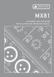
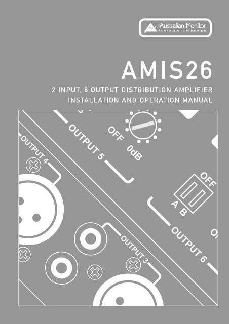
<strong>AMIS26</strong><br />
2 INPUT, 6 OUTPUT DISTRIBUTION AMPLIFIER<br />
INSTALLATION AND OPERATION MANUAL
HEADING<br />
IMPORTANT SAFETY INFORMATION<br />
1. Save the carton and packing material even if the equipment has<br />
arrived in good condition. Should you ever need to ship the unit,<br />
use only the original factory packing.<br />
2. Read all documentation before operating your equipment.<br />
Retain all documentation for future reference.<br />
3. Follow all instructions printed on unit chassis for proper operation.<br />
4. Do not spill water or other liquids into or on the unit, or operate the<br />
unit while standing in liquid.<br />
5. Make sure power outlets conform to the power requirements listed<br />
on the back of the unit.<br />
6. Do not use the unit if the electrical power cord is frayed or broken.<br />
The power supply cords should be routed so that they are not likely<br />
to be walked on or pinched by items placed upon or against them,<br />
paying particular attention to cords and plugs, convenience<br />
receptacles, and the point where they exit from the appliance.<br />
7. Always operate the unit with the AC ground wire connected to the<br />
electrical system ground. Precautions should be taken so that the<br />
means of grounding of a piece of equipment is not defeated.<br />
8. Mains voltage must be correct and the same as that printed on the<br />
rear of the unit. Damage caused by connection to improper AC<br />
voltage is not covered by any warranty.<br />
9. Have gain controls on amplifiers turned down during power-up to<br />
prevent speaker damage if there are high signal levels at the<br />
inputs.<br />
10. Power down & disconnect units from mains voltage before making<br />
connections.<br />
11. Never hold a power switch in the “ON” position if it won’t stay<br />
there itself!<br />
12. Do not use the unit near stoves, heat registers, radiators, or other<br />
heat producing devices<br />
13. Do not block fan intake or exhaust ports. Do not operate<br />
equipment on a surface or in an environment which may impede<br />
the normal flow of air around the unit, such as a bed, rug,<br />
weathersheet, carpet, or completely enclosed rack. If the unit<br />
is used in an extremely dusty or smoky environment, the unit<br />
should be periodically “blown free” of foreign matter.<br />
14. Do not remove the cover. Removing the cover will expose you to<br />
potentially dangerous voltages. There are no user serviceable<br />
parts inside.<br />
15. Do not drive the inputs with a signal level greater than that<br />
required to drive equipment to full output.<br />
16. Do not connect the inputs / outputs of amplifiers or consoles to<br />
any other voltage source, such as a battery, mains source, or<br />
power supply, regardless of whether the amplifier or console is<br />
turned on or off.<br />
17. Do not run the output of any amplifier channel back into another<br />
channel’s input. Do not parallel- or series-connect an amplifier<br />
output with any other amplifier output.<br />
<strong>Australian</strong> <strong>Monitor</strong> Inc is not responsible for damage to<br />
loudspeakers for any reason.<br />
18. Do not ground any red (“hot”) terminal. Never connect a “hot”<br />
(red) output to ground or to another “hot” (red) output!<br />
19. Non-use periods. The power cord of equipment should be unplugged<br />
from the outlet when left unused for a long period of time.<br />
20. Service Information Equipment should be serviced by qualified<br />
service personnel when:<br />
A. The power supply cord or the plug has been damaged.<br />
B. Objects have fallen, or liquid has been spilled into the<br />
equipment<br />
C. The equipment has been exposed to rain<br />
D. The equipment does not appear to operate normally,<br />
or exhibits a marked change in performance<br />
E. The equipment has been dropped, or the enclosure damaged.<br />
THIS SAFETY INFORMATION IS OF A GENERAL NATURE AND MAY BE SUPERSEDED BY INSTRUCTIONS CONTAINED WITHIN THIS MANUAL
INTRODUCTION AND CONTENTS<br />
The <strong>Australian</strong> <strong>Monitor</strong> Installation Series <strong>AMIS26</strong> is a high quality<br />
2 input, 6 output distribution amplifier.<br />
The <strong>AMIS26</strong>’s 2 inputs can be balanced or unbalanced and each input’s<br />
sensitivity can be switched between Mic and Line level. 15VDC<br />
Phantom power is individually switchable per input and for ease of<br />
setup, a four segment LED level meter is provided per input.<br />
Each of the <strong>AMIS26</strong>’s inputs is individually assignable to any of the<br />
6 outputs via front panel DIP switches. Outputs can be balanced or<br />
unbalanced and feature up to 30dB of attenuation, so they can be run<br />
as any combination of line level or mic level outputs. Ample label space<br />
is provided for both inputs and outputs and the <strong>AMIS26</strong> is powered via<br />
a supplied 20VAC power supply.<br />
INTRODUCTION 3<br />
FRONT PANEL 4<br />
REAR PANEL 5<br />
INTERNAL ADJUSTMENT 6<br />
BLOCK DIAGRAM 7<br />
DIMENSIONS 8<br />
SPECIFICATIONS 9<br />
The <strong>AMIS26</strong> provides a low noise, feature packed, signal routing<br />
solution to cover a wide range of installation needs at a contractor<br />
friendly price.<br />
AUS, EUR, USA<br />
Copyright 3rd Dec 2003<br />
Rev A: 3rd Dec 2003<br />
Rev B: 11th Aug 2004<br />
Rev C: 22nd Feb 2005<br />
Rev D: 1st June 2005<br />
This symbol is intended to alert the user to the presence<br />
of uninsulated “dangerous voltage” within the product’s<br />
enclosure that may be of sufficient magnitude to<br />
constitute a risk of electric shock to persons.<br />
This symbol is intended to alert the user to the presence<br />
of important operation and maintenance (servicing)<br />
instructions in the literature accompanying the appliance.<br />
Caution:<br />
To prevent electric shock do not use this (polarised) plug<br />
with an extension cord, receptacle or other outlet unless<br />
the blades can be fully inserted to prevent blade exposure.<br />
To prevent electric shock, match wide blade of plug to<br />
wide slot, fully insert.<br />
<strong>AMIS26</strong> INSTALLATION & OPERATION MANUAL PAGE 3
FRONT PANEL<br />
1 2<br />
3 4<br />
1<br />
INPUT LEVEL CONTROL(S)<br />
The input level controls are screwdriver<br />
adjustable trim pots. The input level controls<br />
can boost or cut the input<br />
signal by up to 15dB.<br />
2<br />
LEVEL METER<br />
These 4 segment LED meters show the<br />
strength of each of the <strong>AMIS26</strong>'s input<br />
signals. LED segments are calibrated to the<br />
following level markings and show<br />
the following colours:<br />
-20dBu (green)<br />
-10dBu (green)<br />
0dBu (yellow)<br />
+10dBu (red)<br />
3<br />
3a<br />
OUTPUT SECTION<br />
3b<br />
4 POWER LED<br />
This blue LED indicates the unit is powered<br />
“on”.<br />
3a INPUT ASSIGN SWITCHES<br />
These recessed DIP switches assign input<br />
A and input B to a desired output.<br />
3b OUTPUT LEVEL CONTROLS<br />
The output level controls are screwdriver<br />
adjustable trim pots. These level controls<br />
attenuate the output level, with a range<br />
from -60dB at 'Minimum” position to 0dB<br />
at “Maximum” position.<br />
PAGE 4<br />
<strong>AMIS26</strong> INSTALLATION & OPERATION MANUAL
REAR PANEL<br />
4 3<br />
2 1<br />
1<br />
2<br />
INPUT A/B CONNECTORS<br />
The balanced XLR inputs can be used<br />
as Mic or Line level inputs and are<br />
switched between input sensitivities via<br />
internal DIP switches accessed through<br />
the lid (see internal adjustments section<br />
page 6). The dual RCA inputs are<br />
Line level inputs only and are internally<br />
summed to mono.<br />
OUTPUT CONNECTORS<br />
The <strong>AMIS26</strong>'s outputs can be either<br />
balanced XLR or unbalanced dual RCA’s.<br />
Both these outputs can be switched<br />
between Mic level & Line level via internal<br />
DIP switches accessed through the lid<br />
(see internal adjustments section page 6).<br />
3<br />
20VAC POWER CONNECTOR<br />
This 2.1mm connector accepts power<br />
from the provided 20VAC power supply.<br />
4<br />
EARTH STUD<br />
In some circumstances it may be<br />
necessary to ground the unit to eliminate<br />
noise in the system. This can be done<br />
by using this earth stud.<br />
NOTE: This stud provides a<br />
connection to chassis ground.<br />
Audio ground is internally tied<br />
to chassis ground.<br />
<strong>AMIS26</strong> INSTALLATION & OPERATION MANUAL PAGE 5
INTERNAL ADJUSTMENT<br />
NOTE: The following adjustments involve access to the inside<br />
of the <strong>AMIS26</strong> and should only be attempted by a qualified technician.<br />
All internal adjustments are accessible through the lid of the <strong>AMIS26</strong>.<br />
Always turn off the AC power and remove the AC power cord before<br />
accessing the inside of the <strong>AMIS26</strong>.<br />
1 2 3<br />
1<br />
INPUT SENSITIVITY DIP<br />
SWITCHES. DIP1 (INPUT A),<br />
DIP3 (INPUT B) SWITCHES 1, 2<br />
2<br />
Switches 1 and 2 on this 3 pole DIP<br />
switch when selected to the “on” position<br />
will switch the balanced XLR input to<br />
Mic level. The “off” position will switch<br />
the balanced XLR input to Line level.<br />
The Default setting is Line level.<br />
NOTE: This switch does not<br />
☛ effect the sensitivity of the<br />
unbalanced dual RCA input.<br />
PHANTOM POWER SWITCH.<br />
DIP1 (INPUT A), DIP3 (INPUT B)<br />
SWITCH 3<br />
This switch will enable 15VDC phantom<br />
power to the desired input. The default<br />
setting is “off”.<br />
NOTE: Before switching Phantom<br />
☛<br />
power on please ensure that no<br />
line level source equipment is<br />
connected to the effected input.<br />
3<br />
OUTPUT LEVEL DIP SWITCH.<br />
DIP 2 Switch 1 (OUTPUT 1)<br />
DIP 2 Switch 2 (OUTPUT 2)<br />
DIP 4 Switch 1 (OUTPUT 3)<br />
DIP 4 Switch 2 (OUTPUT 4)<br />
DIP 5 Switch 1 (OUTPUT 5)<br />
DIP 5 Switch 2 (OUTPUT 6)<br />
This switch will change the output<br />
sensitivity of the desired output from Mic<br />
to Line level. When the switch is “on” the<br />
output level will be switched to Mic level.<br />
NOTE: This switch effects<br />
☛<br />
both balanced XLR & dual<br />
RCA outputs.<br />
PAGE 6<br />
<strong>AMIS26</strong> INSTALLATION & OPERATION MANUAL
BLOCK DIAGRAM<br />
<strong>AMIS26</strong> INSTALLATION & OPERATION MANUAL PAGE 7
DIMENSIONS<br />
PAGE 8<br />
<strong>AMIS26</strong> INSTALLATION & OPERATION MANUAL
SPECIFICATIONS<br />
DIMENSIONS (h x w x d)<br />
44.0 x 482.0 x 168.0 mm<br />
1.73”x19.0”x6.61”<br />
FREQUENCY RESPONSE (0DB/-3DB)<br />
10Hz - 50kHz<br />
SHIPPING DIMENSIONS (h x w x d)<br />
500 x 90.0 x 270.0 mm<br />
3.55”x19.7”x10.6”<br />
THD Line In (XLR/RCA) 0.02%<br />
Mic In (XLR) 0.1%<br />
NOISE<br />
-89dB<br />
WEIGHT<br />
Net 2.5kg Shipping 3.0kg<br />
Net 5.5lb Shipping 6.6lb<br />
CROSSTALK<br />
Better than 80dB<br />
POWER INPUT<br />
20VAC<br />
12VA max<br />
PHANTOM POWER<br />
15VDC<br />
SENSITIVITY (FOR 0dBu OUT)<br />
LINE (XLR)<br />
MIC (XLR)<br />
LINE (RCA)<br />
775mV (0dB)<br />
10mV (-37dB)<br />
775mV (0dB)<br />
MAX IN/OUT(HEADROOM)<br />
All measurements referenced to 0dBu (0.775mV)<br />
All measurements done with levels set In/Out at 0dB<br />
15dB<br />
OUTPUT MIC/LINE GAIN SWITCH<br />
30dB<br />
<strong>AMIS26</strong> INSTALLATION & OPERATION MANUAL PAGE 9
AUSTRALIA AND NEW ZEALAND<br />
www.australianmonitor.com.au<br />
SYDNEY<br />
(NSW & ACT SALES)<br />
MELBOURNE<br />
(VIC & TAS SALES)<br />
BRISBANE<br />
(QLD SALES)<br />
ADELAIDE<br />
(SA & NT SALES)<br />
PERTH<br />
(WA SALES)<br />
AUCKLAND<br />
(NZ SALES)<br />
149 Beaconsfield<br />
Street Silverwater<br />
NSW 2128<br />
Private Bag 149<br />
Silverwater NSW 1811<br />
Phone: (02) 9647 1411<br />
Fax: (02) 9648 3698<br />
Email:<br />
nsw@audiotelex.com.au<br />
22/277<br />
Middleborough Road<br />
Box Hill VIC 3128<br />
PO Box 151 Blackburn<br />
South VIC 3130<br />
Phone: (03) 9890 7477<br />
Fax: (03) 9890 7977<br />
Email:<br />
vic@audiotelex.com.au<br />
42 Commercial Road<br />
Fortitude Valley<br />
QLD 4006<br />
PO Box 871 Fortitude<br />
Valley QLD 4006<br />
Phone: (07) 3852 1312<br />
Fax: (07) 3252 1237<br />
Email:<br />
qld@audiotelex.com.au<br />
31 Walsh Street<br />
Thebarton<br />
SA 5031<br />
PO Box 157<br />
Hindmarsh SA 5007<br />
Phone: (08) 8352 4444<br />
Fax: (08) 8352 4488<br />
Email:<br />
sa@audiotelex.com.au<br />
299 Fitzgerald Street<br />
West Perth WA 6005<br />
PO Box 404<br />
North Perth<br />
WA 6906<br />
Phone: (08) 9228 4222<br />
Fax: (08) 9228 4233<br />
Email:<br />
wa@audiotelex.com.au<br />
Unit B, 11 Piermark<br />
Drive Albany 1331<br />
New Zealand<br />
PO Box 512<br />
Albany 1331<br />
Phone: (09) 415 9426<br />
Fax: (09) 415 9864<br />
Email:<br />
sales@audiotelex.co.nz<br />
EUROPE/ASIA/MIDDLE EAST<br />
www.australianmonitor.com.au<br />
INTERNATIONAL SALES<br />
149 Beaconsfield Street Silverwater NSW 2128 Australia<br />
Private Bag 149 Silverwater NSW 1811<br />
Phone: 61 2 9647 1411<br />
Fax: 61 2 9648 3698<br />
Email: international@audiotelex.com.au<br />
USA/SOUTH AMERICA<br />
www.australianmonitor.com<br />
SENNHEISER ELECTRONIC CORPORATION<br />
1 Enterprise Drive<br />
Old Lyme CT 06371 USA<br />
Phone: 1 860 434 9190<br />
Fax: 1 860 434 1759<br />
Email: jalexander@sennheiserusa.com