av system controller installation and operation manual - SDS Music ...
av system controller installation and operation manual - SDS Music ...
av system controller installation and operation manual - SDS Music ...

Create successful ePaper yourself
Turn your PDF publications into a flip-book with our unique Google optimized e-Paper software.
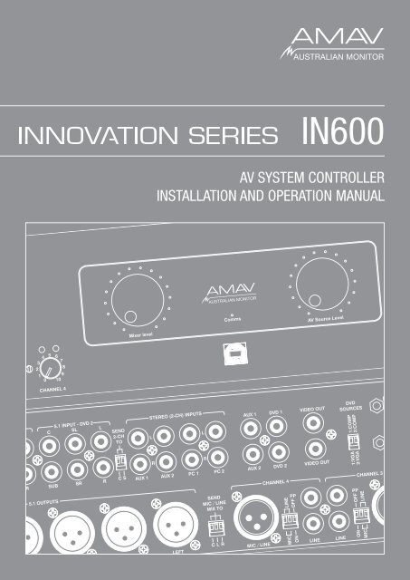
IN600<br />
AV SYSTEM CONTROLLER<br />
INSTALLATION AND OPERATION MANUAL
IMPORTANT SAFETY INFORMATION<br />
1. S<strong>av</strong>e the carton <strong>and</strong> packing material even if the equipment has<br />
arrived in good condition. Should you ever need to ship the unit, use<br />
only the original factory packing.<br />
2. Read all documentation before operating your equipment. Retain<br />
all documentation for future reference.<br />
3. Follow all instructions printed on unit chassis for proper <strong>operation</strong>.<br />
4. Do not spill water or other liquids into or on the unit, or operate<br />
the unit while st<strong>and</strong>ing in liquid.<br />
5. Make sure power outlets conform to the power requirements listed<br />
on the back of the unit.<br />
6. Do not use the unit if the electrical power cord is frayed or broken.<br />
The power supply cords should be routed so that they are not likely<br />
to be walked on or pinched by items placed upon or against them,<br />
paying particular attention to cords <strong>and</strong> plugs, convenience<br />
receptacles, <strong>and</strong> the point where they exit from the appliance.<br />
7. Always operate the unit with the AC ground wire connected to the<br />
electrical <strong>system</strong> ground. Precautions should be taken so that the<br />
means of grounding of a piece of equipment is not defeated.<br />
8. Mains voltage must be correct <strong>and</strong> the same as that printed on the<br />
rear of the unit. Damage caused by connection to improper AC voltage<br />
is not covered by any warranty.<br />
9. H<strong>av</strong>e gain controls on amplifiers turned down during power-up<br />
to prevent speaker damage if there are high signal levels at the inputs.<br />
10 Power down <strong>and</strong> disconnect units from mains voltage before making<br />
connections.<br />
11. Never hold a power switch in the “ON” position if it won’t stay<br />
there itself!<br />
12. Do not use the unit near stoves, heat registers, radiators, or other heat<br />
producing devices.<br />
13. Do not block fan intake or exhaust ports. Do not operate equipment<br />
on a surface or in an environment which may impede the normal flow<br />
of air around the unit, such as a bed, rug, weathersheet, carpet,<br />
or completely enclosed rack. If the unit is used in an extremely dusty<br />
or smoky environment, the unit should be periodically “blown free”<br />
of foreign matter.<br />
14. Do not remove the cover. Removing the cover will expose you<br />
to potentially dangerous voltages. There are no user serviceable<br />
parts inside.<br />
15. Do not drive the inputs with a signal level greater than that required<br />
to drive equipment to full output.<br />
16. Do not connect the inputs / outputs of amplifiers or consoles to any<br />
other voltage source, such as a battery, mains source, or power supply,<br />
regardless of whether the amplifier or console is turned on or off.<br />
17. Do not run the output of any amplifier channel back into another<br />
channel’s input. Do not parallel- or series-connect an amplifier output<br />
with any other amplifier output. Australian Monitor Inc is not<br />
responsible for damage to loudspeakers for any reason.<br />
18. Do not ground any red (“hot”) terminal. Never connect a “hot” (red)<br />
output to ground or to another “hot” (red) output!<br />
19. Non-use periods. The power cord of equipment should be unplugged<br />
from the outlet when left unused for a long period of time.<br />
20. Service Information Equipment should be serviced by qualified service<br />
personnel when:<br />
A. The power supply cord or the plug has been damaged.<br />
B. Objects h<strong>av</strong>e fallen, or liquid has been spilled into the equipment<br />
C. The equipment has been exposed to rain<br />
D. The equipment does not appear to operate normally, or exhibits a<br />
marked change in performance<br />
E. The equipment has been dropped, or the enclosure damaged.<br />
THIS SAFETY INFORMATION IS OF A GENERAL NATURE AND MAY BE SUPERSEDED BY INSTRUCTIONS CONTAINED WITHIN THIS MANUAL
INTRODUCTION AND CONTENTS<br />
The Innovation series from AMAV is a huge step forward in the interfacing <strong>and</strong><br />
management of audio <strong>and</strong> visual sources. Integrating a host of smart, high end<br />
features in a compact package that offers the end user extremely simple control<br />
over their complex audio visual <strong>system</strong>. The Innovation series is as ground<br />
breaking as it is simple to operate.<br />
The IN600 takes the Innovations series concept to the next level in terms<br />
of flexibility <strong>and</strong> complete <strong>system</strong> control. The IN600 features an on board<br />
mic/line mixer, 6 AV source inputs, <strong>and</strong> 6 balanced XLR outputs so it can be<br />
configured as a 5.1 front end. The IN600 also features RS232 for projector<br />
control <strong>and</strong> logic output for screen up/down control. With the IN600 we give the<br />
AV integrator the ability to use the IN600 for full room AV control or it can be<br />
interfaced with third party control <strong>system</strong>s if desired. The IN600 offers untold<br />
flexibility for AV control in an extremely user friendly package.<br />
INTRODUCTION 3<br />
FRONT PANEL 4<br />
REAR PANEL 5<br />
INSTALLATION 6<br />
SETUP / SOFTWARE 7-9<br />
INTERNAL ADJUSTMENTS 10<br />
BLOCK DIAGRAM 11<br />
DIMENSIONS 12<br />
SPECIFICATIONS 13<br />
AUS, EUR, USA<br />
Copyright 21st Aug 2008<br />
REV A 21st Aug 2008<br />
CAUTION<br />
RISK OF ELECTRIC SHOCK<br />
DO NOT OPEN<br />
This symbol is intended to alert the user to the presence of uninsulated<br />
“dangerous voltage” within the products enclosure that may be of sufficient<br />
magnitude to constitute a risk of electric shock to persons.<br />
CAUTION: TO REDUCE THE RISK OF ELECTRIC SHOCK,<br />
DO NOT REMOVE COVER (OR BACK),<br />
NO USER SERVICEABLE PARTS INSIDE,<br />
REFER SERVICING TO QUALIFIED SERVICE PERSONAL.<br />
This symbol is intended to alert the user to the presence of important<br />
<strong>operation</strong>al <strong>and</strong> maintenance (servicing) instructions in the literature<br />
accompanying the appliance.<br />
WARNING!<br />
TO REDUCE THE RISK OF FIRE OR ELECTRIC SHOCK<br />
DO NOT EXPOSE THIS EQUIPMENT TO RAIN OR MOISTURE.<br />
Caution:<br />
To prevent electric shock do not use this (polarised) plug with an extension<br />
cord, receptacle or other outlet unless the blades can be fully inserted to<br />
prevent blade exposure. To prevent electric shock, match wide blade of<br />
plug to wide slot, fully insert.<br />
IN600 INSTALLATION AND OPERATION MANUAL<br />
PAGE 3
front PANEL<br />
4 3<br />
7<br />
11<br />
9<br />
12<br />
1 2<br />
6 13 14 5<br />
10<br />
8<br />
1 GAIN TRIM<br />
This control is used to adjust the input gain <strong>and</strong> affects both the XLR <strong>and</strong> the<br />
RCA inputs. The input gain can be adjusted by +/- 15dB. This allows a wide rage<br />
of program sources to be set up with optimum gain structure. With the gain trim<br />
in the centre position, the boost/cut is set to 0dB.<br />
2 LEVEL<br />
Controls the level of the input signal.<br />
9 SOURCE SELECT LEDS<br />
The LED above the switch indicates when the AV source is being routed to the<br />
audio <strong>and</strong> video outputs. OFF indicates no source is routed to the outputs.<br />
10 PROJECTOR POWER SWITCH<br />
This switch is used to control a projector. Pushing this button will send data<br />
control comm<strong>and</strong>s out the PROJECTOR COMMS connector <strong>and</strong> trigger the<br />
screen relays.<br />
3 INPUT STATUS LEDS<br />
Each input has an LED status indicator. The LED is green when there is signal<br />
present <strong>and</strong> red if the signal is approaching clip. If the LED begins to light red<br />
this would indicate the internal signal level is 6dB before clip. Note that the<br />
front panel level control is post status LED <strong>and</strong> as such, the status LED is NOT<br />
affected by the level control. If an input channel is clipping use the gain control to<br />
adjust the correct amount of input level.<br />
4 INPUT SELECTED LEDS<br />
Each input can be switched on or off seperately via PC or RS485. This LED<br />
indicates when the when the channel is selected.<br />
5 AV SOURCE MASTER<br />
This pot controls the level of the selected AV source.<br />
6 MIC/LINE MASTER<br />
This pot controls the overall mixed level of the Mic/Line sources.<br />
7 MASTER VOLUME LEDS<br />
These LED’s indicate the position of the volume control. They do not indicate the<br />
strength of the signal.<br />
8 SOURCE SELECT SWITCHES<br />
These switches select the input that is routed to the audio <strong>and</strong> video outputs.<br />
OFF will not route any source to the output.<br />
11 PROJECTOR POWER LED<br />
This LED indiactes the state of the projecter.<br />
Projector Power LED state<br />
1. LED flashing means the projector has sent a comm<strong>and</strong> <strong>and</strong> assumes the<br />
projector is now warming up or cooling down. If the button is pushed again while<br />
the LED is flashing nothing happens.<br />
2. LED on means the projector has been sent an ON comm<strong>and</strong> <strong>and</strong> the<br />
necessary warmup period has elapsed.<br />
3. LED off means the projector has been sent an OFF comm<strong>and</strong> <strong>and</strong> the<br />
necessary cool down period has elapsed.<br />
Projector communication is only one way so the actual state of this projector<br />
may not match the state of the LED. If this happens, set the projector to off <strong>and</strong><br />
then switch of the IN600. Switch the IN600 on <strong>and</strong> now both projector <strong>and</strong> LED<br />
should be off.<br />
12 POWER ON LED<br />
The AMAV logo will be illuminated when the unit is on.<br />
13 USB Socket<br />
This is a Type B USB connector used to connect the I600 to a PC.<br />
14 COMMS LED<br />
This LED indicates when data is sent or revceived via PC or RS485.<br />
PAGE 4<br />
IN600 INSTALLATION AND OPERATION MANUAL
REAR PANEL<br />
16 15 14<br />
5 7 6 9 10 13<br />
11<br />
12<br />
17<br />
4 8 2 1 3<br />
1 CHANNEL INPUTS<br />
Each channel has two inputs:<br />
XLR input - This is a balanced input. It accepts mic or line level signals depending<br />
on the adjacent gain switch position. The XLR will also h<strong>av</strong>e +15V phantom power if<br />
selected on the adjacent switch.<br />
RCA input - This is an unbalanced line level input. The two RCA sockets are<br />
summed to mono internally.<br />
2 P/P (PHANTOM POWER)<br />
15V phantom power is <strong>av</strong>ailable for condenser or electret microphones on the XLR<br />
input when this switch is in the ‘ON’ position.<br />
3 MIC / LINE<br />
These two switches control the sensitivity of the XLR input. In the ‘MIC’ position the<br />
XLR input is suitable for use with microphones; in the ‘LINE’ position the XLR input<br />
is suitable for use with a balanced line level signal.<br />
4 5.1 OUTPUTS<br />
Note: Both MIC/LINE switches must be in the same position for<br />
correct <strong>operation</strong> of the balanced input.<br />
Note: The MIC/LINE switches only affect the XLR input.<br />
The 5.1 OUTPUT XLRs provide balanced line level signal.<br />
5 5.1 INPUTS<br />
Note: When wiring the XLR output as unbalanced, Pin2 should be<br />
wired as hot <strong>and</strong> Pin1 should be wired as ground/shield. Do not wire Pin3.<br />
These are the RCA unbalanced line level audio inputs for the DVD1 <strong>and</strong> DVD2<br />
sources.<br />
6 STEREO (2CH) INPUTS<br />
These are the RCA unbalanced line level audio inputs for the AUX1/AUX2/PC1/PC2<br />
sources.<br />
7 SEND 2-CH TO<br />
These DIP switches allow the STEREO INPUTS to be routed to the CENTRE (C)<br />
output <strong>and</strong>/or the S-RIGHT/S-LEFT (S) outputs as well as still going the LEFT <strong>and</strong><br />
RIGHT outputs. The left <strong>and</strong> right signals are summed together for the CENTRE<br />
output. The down postion means the audio is routed. The default setting is off (up).<br />
8 SEND MIC/LINE MIX TO<br />
These DIP switches allow the MIC/LINE INPUTS to be routed to the CENTRE (C)<br />
output, LEFT output (L) <strong>and</strong> RIGHT output (R) or not. The down postion means the<br />
audio is routed. Up position means the audio is not routed to any output. The default<br />
setting is on (down).<br />
IN600 INSTALLATION AND OPERATION MANUAL<br />
9 VIDEO INPUT<br />
These are RCA unbalanced 75ohm composite video inputs for the DVD1/DVD2/<br />
AUX1/AUX2 sources.<br />
10 VIDEO OUTPUT<br />
These are the RCA unbalanced 75ohm composite video outputs. OUT1 <strong>and</strong> OUT2<br />
output the same signal but they are individually buffered. These outputs only output<br />
the signal from DVD1/DVD2/AUX1/AUX2 sources if selected.<br />
11 VGA INPUT<br />
These are high densisty 15pin D connector VGA inputs for the DVD1/DVD2/PC1/<br />
PC2 sources.<br />
12 VGA OUTPUT<br />
This is the high densisty 15pin D connector VGA output. This output only outputs the<br />
signal from DVD1/DVD2/PC1/PC2 sources if selected.<br />
13 DVD SOURCES<br />
These DIP switches are used to set the DVD source type. Selecting COMP means<br />
the DVD video signal is coming in on the composite VIDEO connector <strong>and</strong> is<br />
swithced to the composite VIDEO output. Selecting VGA means the DVD video<br />
signal is coming in on the VGA connector <strong>and</strong> is switched to the VGA output.<br />
This is needed to make sure the correct data codes are sent on the RS485 <strong>and</strong><br />
PROJECTOR COMMS.<br />
14 RS485<br />
This 3.81mm pluggable connector socket is provided for external control of the<br />
IN600 using RS485 or for connecting an Australian Monitor control panel.<br />
15 SCREEN<br />
This 3.81mm pluggable connector output is used to trigger projector screen<br />
controls. These are voltage free contacts that short to COM when activated. They<br />
are activated by the powering of the projector. When the projector is switched on<br />
the screen down contacts are activated. When the projector is switched off the<br />
screen up contacts are activated. The relays stay closed for the period set in the<br />
configuration software.<br />
16 PROJECTOR COMMS<br />
This 9 pin D-connector is for sending data to a projector.<br />
17 IEC MAINS INPUT SOCKET<br />
This is a st<strong>and</strong>ard IEC 3 pin socket (IEC320-C14). It accepts a st<strong>and</strong>ard IEC mains<br />
cable, provided. The fuse draw contains the mains fuse <strong>and</strong> a spare. The mains fuse<br />
is a time lag (slow blow) HRC 20mm x 5mm fuse. The ratings are:<br />
230V/240V model 200mA<br />
115V model 500mA<br />
Always replace the fuse with one of the same value <strong>and</strong> type.<br />
Note: Always disconnect power to the amplifier before replacing fuses.<br />
PAGE 5
<strong>installation</strong><br />
All <strong>installation</strong> work should be done with the power disconnected. The following information will help with <strong>installation</strong>. After <strong>installation</strong> is complete power up in the<br />
following order:<br />
1. All the sources<br />
2. IN600<br />
3. All amplifiers<br />
POWER CONNECTION<br />
BREAK OUT CABLE<br />
Ensure the mains voltage supply matches the rear of the IN600 (+/- 10%).<br />
Ensure that all <strong>system</strong> grounds (earth) are connected to a common point. Avoid<br />
powering equipment within a <strong>system</strong> from multiple power sources that may be<br />
separated by large distances. This will eliminate ground loops that are heard<br />
as 50/60Hz humming or buzzing in speakers <strong>and</strong> seen as moving or stationary<br />
bars on video equipment.<br />
OUTPUT CONNECTION<br />
Component video can be used on the IN600<br />
by using a VGA break out cable. A break out<br />
cable is required for all devices. There is no<br />
internal VGA to component conversion within<br />
the IN600. (ie. the lines are simply switched <strong>and</strong><br />
the component signals require sync on them, eg<br />
sync on green). You can not use a VGA source in<br />
to a component source out for example.<br />
Video<br />
Video outputs are on either unbalanced RCA sockets (composite) or 15 pin high<br />
density female connectors D-connectors (VGA). The maximum cable length for<br />
composite video is typically less than 3m for shielded wire <strong>and</strong> 10m for coaxial<br />
before signal degradation. This will depend on the cable quality.<br />
There are two composite outputs for running to 2 different monitors without the<br />
need for an external distribution amplifier.<br />
VGA pin out<br />
1 Red out<br />
2 Green out<br />
3 Blue out<br />
4 Monitor ID 2 in<br />
5 Ground<br />
6 Red return<br />
7 Green return<br />
8 Blue return<br />
9 no pin<br />
10 Sync return<br />
11 Monitor ID 0 in<br />
12 Monitor ID 1 in<br />
13 Horizonal Sync out<br />
14 Vertical Sync out<br />
15 reserved (monitor ID 3)<br />
Only pins 1,2,3,5,6,7,8,10,13,14 are used in the IN600.<br />
INPUT CONNECTIONS<br />
Audio<br />
All the inputs are unbalanced RCA sockets. Unbalanced RCA wiring should be<br />
keep as short as possible. Typically less than 3m.<br />
Video<br />
Video inputs are on either unbalanced RCA sockets (composite) or 15 pin high<br />
density female connectors D-connectors (VGA). The maximum cable length for<br />
composite video is typically less than 3m for shielded wire <strong>and</strong> 10m for coaxial<br />
before signal degradation. This will depend on the cable quality.<br />
RS485 CONNECTIONS<br />
The RS485 data port is on a 5.08mm pluggable connectors. Twisted pair<br />
cabling should be used When connecting RS485 devices, such as CAT3, CAT5,<br />
CAT5e or CAT6 UTP cabling. RS485 data networks should be wired in a ‘daisy<br />
chain’ configuration with a maximum of 32 devices in the chain. The IN400 is<br />
not terminated so may be inserted anywhere in the data network. If the IN600 is<br />
being used at the end of a chain, a 120ohm (characteristic impedance of UTP)<br />
terminating resistor should be connected between the + <strong>and</strong> - connections.<br />
The maximum length of the chain is 1200m (4000’).<br />
PAGE 6<br />
IN600 INSTALLATION AND OPERATION MANUAL
RS485 COMMANDS<br />
Data: 19200, 8N1<br />
All ASCII characters<br />
The comm<strong>and</strong>s are pure ASCII. So a hex value of 0xA5 (decimal 165) is sent as ASCII ‘A’ ‘5’, or 0x41 0x35.<br />
eg Comm<strong>and</strong> !04GR01?? is sent as a hex string 0x21 0x30 0x34 0x47 0x52 0x30 0x31 0x3F 0x3F 0x0D<br />
GET COMMANDS<br />
Object Data Response Data<br />
!04GR01?? Get source volume !04SR01XX XX-volume setting 00-FF (00 is min)<br />
!08GR01?? Get mic/line volume !08SR01XX XX-volume setting 00-FF (00 is min)<br />
!04GL01?? Get source mute state !04SL01YY YY-ON,OF,FL (On,Off, Flashing)<br />
!08GLXX?? Get mic/line enabled state XX-mic/line channel 01-04 !08SLXXYY XX-mic/line channel 01-04; YY-ON,OF,FL (On,Off, Flashing)<br />
!10GLXX?? Get source/projector state XX-source channel 01-06, 07-<br />
off, 08-projector<br />
!10SLXXYY<br />
XX-source channel 01-06, 07-off, 08-projector; YY-ON,OF,FL<br />
(On,Off, Flashing)<br />
SET COMMANDS<br />
These comm<strong>and</strong>s are used to set values on the IN600. Good programming techinique should update control <strong>system</strong> visual info on the feedback responses not the ACK<br />
message, see Feedback table.<br />
Object Data ACK NACK<br />
!04SR01XX Set source volume XX-volume setting 00-FF (00 is min) !04A !04N<br />
!08SR01XX Set mic/line volume XX-volume setting 00-FF (00 is min) !08A !08N<br />
!04SB01SH Mute source !04A !04N<br />
!08SBXXSH Enable/Disable Mic/Line XX-mic/line channel 01-04 !08A !08N<br />
!10SBXXSH Select source/toggle projector XX-source channel 01-06, 07-off, 08-projector !10A !10N<br />
FEEDBACK RESPONSES<br />
These messages are sent from the IN600 when changes occur in the IN600. This includes RS485 Set comm<strong>and</strong>s as well as front panel changes.<br />
Object<br />
Data<br />
*01SR01XX When the source volume changes XX-volume setting 00-FF (00 is min)<br />
*02SR01XX When the mic/line volume changes XX-volume setting 00-FF (00 is min)<br />
*01SL01YY When the source mute state changes YY-ON,OF,FL (On,Off, Flashing)<br />
*02SLXXYY When the Mic/Line enabled stated changes XX-mic/line channel 01-04; YY-ON,OF,FL (On,Off, Flashing)<br />
*03SLXXYY When the selected source or projector changes XX-source channel 01-06, 07-off, 08-projector; YY-ON,OF,FL (On,Off, Flashing)<br />
IN600 INSTALLATION AND OPERATION MANUAL<br />
PAGE 7
SETUP / SOFTWARE<br />
The IN600 software come included on a CD ROM. The IN600 software will work on any windows XP or later operating <strong>system</strong>. Installing the software is easy insert the<br />
CD <strong>and</strong> run the setup.exe file. Follow the prompts.<br />
You should close down the software before disconnecting the IN600 from the USB port.The IN600 can be safely connected <strong>and</strong> disconnect from the USB port at anytime<br />
when the software is not running.<br />
2<br />
4<br />
1 3<br />
5<br />
6<br />
Main Window<br />
1 Mic Level<br />
This is the software equivalent of the MIC/LINE MASTER pot on the front panel.<br />
2 Enable<br />
These check boxes allow you to enable or disable the 4 mic/line channels<br />
individually. Selected channels will h<strong>av</strong>e there INPUT SELECTED LEDS on, shown<br />
on the front panel. The labels can be changed in the Configuration/Set Input<br />
Names menu item.<br />
3 Source Level<br />
This is the software equivalent of the AV SOURCE MASTER pot on the front panel.<br />
4 Source Select<br />
These radio buttons toggle the selected source. The labels can be changed in the<br />
Configuration/Set Input Names menu item.<br />
5 Turn Projector On/Off buttons<br />
These buttons control the <strong>operation</strong> of the projector if one is connected to the<br />
IN600. The codes that are sent to the projector can be set in the Configuration/<br />
Set Projector Codes menu option. Only one button button is highlighted at a time<br />
indicating the state of the projector. If the Turn Projector On button is highlighted<br />
then a Turn Projector Off code must h<strong>av</strong>e been sent at some time previously. If<br />
the Turn Projector Off button is highlighted then a Turn Project On code must h<strong>av</strong>e<br />
been sent at some time previously.<br />
6 Status bar<br />
Note: Projector comms is uni-directional only. Comm<strong>and</strong>s are sent to<br />
the projector, no comm<strong>and</strong>s are recieved. It is possible that the<br />
Projector can be out of sync with the IN600. If this happens the IN600<br />
should be set to show the projector is off <strong>and</strong> then the projector should<br />
be <strong>manual</strong>ly switched off.<br />
The status bar shows the state off the computer <strong>and</strong> software connection. The first<br />
word (USB Disconnected or USB Connected) indiactes if the IN600 is connected<br />
to the USB port <strong>and</strong> the operating <strong>system</strong> has recognized it. There is no software<br />
control associated with this indication. The second word (IN600 Offline or IN600<br />
Online) indicates if the setup software is communicating with the IN600. If it is<br />
online then changes made in the software are immediately seen on the IN600.<br />
This is a real time connection. If it is offline then changes made in the software<br />
wont change the IN600 until a connection is made. When a connection is made<br />
the user is given the option to upload the software configuration. Connection is<br />
made in the Configuration/Connect menu item.<br />
PAGE 8<br />
IN600 INSTALLATION AND OPERATION MANUAL
SETUP / SOFTWARE Continued<br />
1<br />
3<br />
2<br />
4<br />
File menu<br />
This menu contains the st<strong>and</strong>ard Windows File options.<br />
1 Open<br />
Opens a .in6 file which contains a previously s<strong>av</strong>e configuration of the software.<br />
Opening a file will overwrite your current configuration. If the IN600 is Online then<br />
opening a file will load the contents straight up to the IN600.<br />
2 S<strong>av</strong>e<br />
This will prompt you to s<strong>av</strong>e the file with the name of the open file. If no file has<br />
been opened you can s<strong>av</strong>e it as any name.<br />
3 S<strong>av</strong>e As<br />
Allows you to s<strong>av</strong>e the configuration of the set software as a .in6 file.<br />
4 Exit<br />
Closes the application.<br />
IN600 INSTALLATION AND OPERATION MANUAL<br />
PAGE 9
SETUP / SOFTWARE Continued<br />
1<br />
2<br />
3<br />
4<br />
3<br />
Configuration menu<br />
1 Set Projector Codes<br />
This menu item will open the Projector Setup window.<br />
2 Set Input Names<br />
Allows you to set the names of the Mic/Line inputs <strong>and</strong> the AV sources. These are<br />
stored in the EEPROM of the IN600 itself <strong>and</strong> is limited to 8 charaters.<br />
3 Set Power Up Values<br />
This button opens a window to configure the power up settings. The power up<br />
settings is the way the unit will be set after powering up. The window asks if<br />
you would like to download the current power up configuration stored in the<br />
IN600 or store the current configuration of the software as the default power up<br />
configuration. Note that changes made to the unit from either the software or the<br />
front panel are not automatically s<strong>av</strong>ed <strong>and</strong> recalled when turning off the IN600 or<br />
exiting the software.<br />
5 Connect/Disconnect<br />
This menu item will be showing either Connect or Disconnect.<br />
Connect<br />
If it is showing Connect then selecting it will cause the software to try <strong>and</strong> connect<br />
to the IN600. When a connection is made the user is given the option to upload the<br />
software configuration or download the actual IN600 configuration to the software.<br />
Uploading software will overwrite the setting on the IN600. Downloading from the<br />
IN600 will overwrite the software settings. Once connected, changes made in the<br />
software are immediately seen on the IN600. This is a real time connection. The<br />
status bar at the bottom of the main window will show IN600 Online.<br />
Disconnect<br />
If it is showing Disconnect then selecting it will cause the software to go Offline.<br />
If it is offline then changes made in the software wont change the IN600 until a<br />
connection is made. The status bar at the bottom of the main window will show<br />
Offline.<br />
4 Turn Project Off / Turn Projector On<br />
These correspond to the buttons in the main window. See ‘Main Window’ above.<br />
PAGE 10<br />
IN600 INSTALLATION AND OPERATION MANUAL
SETUP / SOFTWARE Continued<br />
Project Setup window<br />
This window allows you to set the parameters of the RS232 port used to connect to a projector. You can set all the parameters of the communication protocol; Baud Rate,<br />
Parity, No of Data Bits, No of Stop Bits.<br />
1<br />
2<br />
3<br />
1 Projector Timeouts<br />
This is the number of seconds (integer values only) that the IN600 will wait before<br />
allowing another comm<strong>and</strong> to be set to the projector when an On/Off comm<strong>and</strong><br />
is sent. This allows time for the projector to warm up or cool down. Consult the<br />
projectors manufacturer data for information on warm up <strong>and</strong> cool down times.<br />
Integer values between 1 <strong>and</strong> 300 are accepted.<br />
3 Screen<br />
This is the number of seconds the SCREEN up/down relay contacts will stay closed<br />
for controlling the screen motor. It is accurate to 0.1 seconds <strong>and</strong> accepts values<br />
from 0.1 to 25.5.<br />
2 Projector Strings<br />
These are the strings that will be sent to projector. When the projector power<br />
button is pushed on the IN600 the on or off code is sent. When a source is<br />
selected the corresponding video format code is sent.<br />
DVD1<br />
DVD2<br />
AUX1<br />
AUX2<br />
PC1<br />
PC2<br />
Table 1<br />
depends on setting of back panel DIP switch<br />
Video code set<br />
VGA code sent<br />
A maximum of 20 characters can be sent. /x will cause the next 2 characters to be<br />
read as a hex value. eg /x20 will send hex value 20 (ASCII-space).<br />
The test buttons allow these strings to be sent to the projector. The IN600 must be<br />
Online for these to work.<br />
IN600 INSTALLATION AND OPERATION MANUAL<br />
PAGE 11
INTERNAL ADJUSTMENTS<br />
1 2 3<br />
The following routing configurations can be made inside the IN600. Access to the inside the the IN600 should only be performed by a qualified person.<br />
1 Mic/Line HPF<br />
Each of the 4 mic/line inputs has a 150Hz HPF. Moving the jumper to the<br />
IN position will enable the filter. The factory default is OUT.<br />
2 Mic/Line mix to...<br />
The mic/line mix can be sent to the the surround sound left <strong>and</strong> right <strong>and</strong>/or the<br />
sub output. There are 3 jumpers with two postions, on or off. The default setting<br />
is off.<br />
3 Stereo channels to surround output<br />
The stereo mixed signal can be routed to the rear surround left <strong>and</strong> right outputs.<br />
There are 2 jumpers with two positions. The left input will go to the left surround<br />
output when the left jumper is set <strong>and</strong> the right input will go to the right surround<br />
output when the right jumper is set. The default setting is off.<br />
PAGE 12<br />
IN600 INSTALLATION AND OPERATION MANUAL
BLOCK DIAGRAM<br />
IN600 INSTALLATION AND OPERATION MANUAL<br />
PAGE 13
DIMENSIONS<br />
PAGE 14<br />
IN600 INSTALLATION AND OPERATION MANUAL
specifications<br />
Line Audio THD
AUSTRALIA AND NEW ZEALAND<br />
www.australianmonitor.com.au<br />
SYDNEY<br />
MELBOURNE<br />
BRISBANE<br />
ADELAIDE<br />
PERTH<br />
AUCKLAND<br />
(NSW & ACT SALES)<br />
(VIC & TAS SALES)<br />
(QLD SALES)<br />
(SA & NT SALES)<br />
(WA SALES)<br />
(NZ SALES)<br />
1 Clyde Street<br />
Silverwater<br />
NSW 2128<br />
Private Bag 149<br />
Silverwater NSW 1811<br />
Phone: (02) 9647 1411<br />
Fax: (02) 9648 3698<br />
Email:<br />
nsw@audiotelex.com.au<br />
22/277<br />
Middleborough Road<br />
Box Hill VIC 3128<br />
PO Box 151 Blackburn<br />
South VIC 3130<br />
Phone: (03) 9890 7477<br />
Fax: (03) 9890 7977<br />
Email:<br />
vic@audiotelex.com.au<br />
42 Commercial Road<br />
Fortitude Valley<br />
QLD 4006<br />
PO Box 2578 Fortitude<br />
Valley BC QLD 4006<br />
Phone: (07) 3852 1312<br />
Fax: (07) 3252 1237<br />
Email:<br />
qld@audiotelex.com.au<br />
31 Walsh Street<br />
Thebarton<br />
SA 5031<br />
PO Box 157<br />
Hindmarsh SA 5007<br />
Phone: (08) 8352 4444<br />
Fax: (08) 8352 4488<br />
Email:<br />
sa@audiotelex.com.au<br />
3/11 Howe Street<br />
Osborne Park WA 6017<br />
PO Box 1281<br />
Osborne Park BC<br />
WA 6916<br />
Phone: (08) 9204 0200<br />
Fax: (08) 9244 3783<br />
Email:<br />
wa@audiotelex.com.au<br />
9C Piermark Drive<br />
Albany 0752<br />
New Zeal<strong>and</strong><br />
PO Box 300-512<br />
Albany 0752<br />
Phone: (09) 415 9426<br />
Fax: (09) 415 9864<br />
Email:<br />
sales@audiotelex.co.nz<br />
EUROPE / ASIA / MIDDLE EAST<br />
www.australianmonitor.com.au<br />
INTERNATIONAL SALES<br />
1 Clyde Street Silverwater NSW 2128 Australia<br />
Private Bag 149 Silverwater NSW 1811<br />
Phone: + 61 2 9647 1411<br />
Fax: + 61 2 9648 3698<br />
Email: international@audiotelex.com.au