av system controller installation and operation manual - SDS Music ...
av system controller installation and operation manual - SDS Music ...
av system controller installation and operation manual - SDS Music ...

Create successful ePaper yourself
Turn your PDF publications into a flip-book with our unique Google optimized e-Paper software.
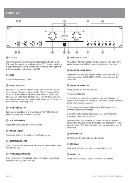
front PANEL<br />
4 3<br />
7<br />
11<br />
9<br />
12<br />
1 2<br />
6 13 14 5<br />
10<br />
8<br />
1 GAIN TRIM<br />
This control is used to adjust the input gain <strong>and</strong> affects both the XLR <strong>and</strong> the<br />
RCA inputs. The input gain can be adjusted by +/- 15dB. This allows a wide rage<br />
of program sources to be set up with optimum gain structure. With the gain trim<br />
in the centre position, the boost/cut is set to 0dB.<br />
2 LEVEL<br />
Controls the level of the input signal.<br />
9 SOURCE SELECT LEDS<br />
The LED above the switch indicates when the AV source is being routed to the<br />
audio <strong>and</strong> video outputs. OFF indicates no source is routed to the outputs.<br />
10 PROJECTOR POWER SWITCH<br />
This switch is used to control a projector. Pushing this button will send data<br />
control comm<strong>and</strong>s out the PROJECTOR COMMS connector <strong>and</strong> trigger the<br />
screen relays.<br />
3 INPUT STATUS LEDS<br />
Each input has an LED status indicator. The LED is green when there is signal<br />
present <strong>and</strong> red if the signal is approaching clip. If the LED begins to light red<br />
this would indicate the internal signal level is 6dB before clip. Note that the<br />
front panel level control is post status LED <strong>and</strong> as such, the status LED is NOT<br />
affected by the level control. If an input channel is clipping use the gain control to<br />
adjust the correct amount of input level.<br />
4 INPUT SELECTED LEDS<br />
Each input can be switched on or off seperately via PC or RS485. This LED<br />
indicates when the when the channel is selected.<br />
5 AV SOURCE MASTER<br />
This pot controls the level of the selected AV source.<br />
6 MIC/LINE MASTER<br />
This pot controls the overall mixed level of the Mic/Line sources.<br />
7 MASTER VOLUME LEDS<br />
These LED’s indicate the position of the volume control. They do not indicate the<br />
strength of the signal.<br />
8 SOURCE SELECT SWITCHES<br />
These switches select the input that is routed to the audio <strong>and</strong> video outputs.<br />
OFF will not route any source to the output.<br />
11 PROJECTOR POWER LED<br />
This LED indiactes the state of the projecter.<br />
Projector Power LED state<br />
1. LED flashing means the projector has sent a comm<strong>and</strong> <strong>and</strong> assumes the<br />
projector is now warming up or cooling down. If the button is pushed again while<br />
the LED is flashing nothing happens.<br />
2. LED on means the projector has been sent an ON comm<strong>and</strong> <strong>and</strong> the<br />
necessary warmup period has elapsed.<br />
3. LED off means the projector has been sent an OFF comm<strong>and</strong> <strong>and</strong> the<br />
necessary cool down period has elapsed.<br />
Projector communication is only one way so the actual state of this projector<br />
may not match the state of the LED. If this happens, set the projector to off <strong>and</strong><br />
then switch of the IN600. Switch the IN600 on <strong>and</strong> now both projector <strong>and</strong> LED<br />
should be off.<br />
12 POWER ON LED<br />
The AMAV logo will be illuminated when the unit is on.<br />
13 USB Socket<br />
This is a Type B USB connector used to connect the I600 to a PC.<br />
14 COMMS LED<br />
This LED indicates when data is sent or revceived via PC or RS485.<br />
PAGE 4<br />
IN600 INSTALLATION AND OPERATION MANUAL