av system controller installation and operation manual - SDS Music ...
av system controller installation and operation manual - SDS Music ...
av system controller installation and operation manual - SDS Music ...

You also want an ePaper? Increase the reach of your titles
YUMPU automatically turns print PDFs into web optimized ePapers that Google loves.
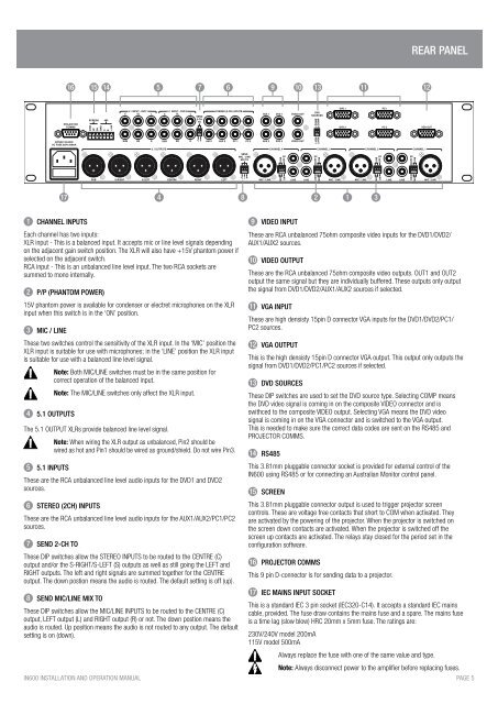
REAR PANEL<br />
16 15 14<br />
5 7 6 9 10 13<br />
11<br />
12<br />
17<br />
4 8 2 1 3<br />
1 CHANNEL INPUTS<br />
Each channel has two inputs:<br />
XLR input - This is a balanced input. It accepts mic or line level signals depending<br />
on the adjacent gain switch position. The XLR will also h<strong>av</strong>e +15V phantom power if<br />
selected on the adjacent switch.<br />
RCA input - This is an unbalanced line level input. The two RCA sockets are<br />
summed to mono internally.<br />
2 P/P (PHANTOM POWER)<br />
15V phantom power is <strong>av</strong>ailable for condenser or electret microphones on the XLR<br />
input when this switch is in the ‘ON’ position.<br />
3 MIC / LINE<br />
These two switches control the sensitivity of the XLR input. In the ‘MIC’ position the<br />
XLR input is suitable for use with microphones; in the ‘LINE’ position the XLR input<br />
is suitable for use with a balanced line level signal.<br />
4 5.1 OUTPUTS<br />
Note: Both MIC/LINE switches must be in the same position for<br />
correct <strong>operation</strong> of the balanced input.<br />
Note: The MIC/LINE switches only affect the XLR input.<br />
The 5.1 OUTPUT XLRs provide balanced line level signal.<br />
5 5.1 INPUTS<br />
Note: When wiring the XLR output as unbalanced, Pin2 should be<br />
wired as hot <strong>and</strong> Pin1 should be wired as ground/shield. Do not wire Pin3.<br />
These are the RCA unbalanced line level audio inputs for the DVD1 <strong>and</strong> DVD2<br />
sources.<br />
6 STEREO (2CH) INPUTS<br />
These are the RCA unbalanced line level audio inputs for the AUX1/AUX2/PC1/PC2<br />
sources.<br />
7 SEND 2-CH TO<br />
These DIP switches allow the STEREO INPUTS to be routed to the CENTRE (C)<br />
output <strong>and</strong>/or the S-RIGHT/S-LEFT (S) outputs as well as still going the LEFT <strong>and</strong><br />
RIGHT outputs. The left <strong>and</strong> right signals are summed together for the CENTRE<br />
output. The down postion means the audio is routed. The default setting is off (up).<br />
8 SEND MIC/LINE MIX TO<br />
These DIP switches allow the MIC/LINE INPUTS to be routed to the CENTRE (C)<br />
output, LEFT output (L) <strong>and</strong> RIGHT output (R) or not. The down postion means the<br />
audio is routed. Up position means the audio is not routed to any output. The default<br />
setting is on (down).<br />
IN600 INSTALLATION AND OPERATION MANUAL<br />
9 VIDEO INPUT<br />
These are RCA unbalanced 75ohm composite video inputs for the DVD1/DVD2/<br />
AUX1/AUX2 sources.<br />
10 VIDEO OUTPUT<br />
These are the RCA unbalanced 75ohm composite video outputs. OUT1 <strong>and</strong> OUT2<br />
output the same signal but they are individually buffered. These outputs only output<br />
the signal from DVD1/DVD2/AUX1/AUX2 sources if selected.<br />
11 VGA INPUT<br />
These are high densisty 15pin D connector VGA inputs for the DVD1/DVD2/PC1/<br />
PC2 sources.<br />
12 VGA OUTPUT<br />
This is the high densisty 15pin D connector VGA output. This output only outputs the<br />
signal from DVD1/DVD2/PC1/PC2 sources if selected.<br />
13 DVD SOURCES<br />
These DIP switches are used to set the DVD source type. Selecting COMP means<br />
the DVD video signal is coming in on the composite VIDEO connector <strong>and</strong> is<br />
swithced to the composite VIDEO output. Selecting VGA means the DVD video<br />
signal is coming in on the VGA connector <strong>and</strong> is switched to the VGA output.<br />
This is needed to make sure the correct data codes are sent on the RS485 <strong>and</strong><br />
PROJECTOR COMMS.<br />
14 RS485<br />
This 3.81mm pluggable connector socket is provided for external control of the<br />
IN600 using RS485 or for connecting an Australian Monitor control panel.<br />
15 SCREEN<br />
This 3.81mm pluggable connector output is used to trigger projector screen<br />
controls. These are voltage free contacts that short to COM when activated. They<br />
are activated by the powering of the projector. When the projector is switched on<br />
the screen down contacts are activated. When the projector is switched off the<br />
screen up contacts are activated. The relays stay closed for the period set in the<br />
configuration software.<br />
16 PROJECTOR COMMS<br />
This 9 pin D-connector is for sending data to a projector.<br />
17 IEC MAINS INPUT SOCKET<br />
This is a st<strong>and</strong>ard IEC 3 pin socket (IEC320-C14). It accepts a st<strong>and</strong>ard IEC mains<br />
cable, provided. The fuse draw contains the mains fuse <strong>and</strong> a spare. The mains fuse<br />
is a time lag (slow blow) HRC 20mm x 5mm fuse. The ratings are:<br />
230V/240V model 200mA<br />
115V model 500mA<br />
Always replace the fuse with one of the same value <strong>and</strong> type.<br />
Note: Always disconnect power to the amplifier before replacing fuses.<br />
PAGE 5