View-Based Modeling of Function Nets - Software Engineering
View-Based Modeling of Function Nets - Software Engineering
View-Based Modeling of Function Nets - Software Engineering

Create successful ePaper yourself
Turn your PDF publications into a flip-book with our unique Google optimized e-Paper software.
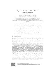
Figure 3. Excerpt from an automotive function<br />
net (Signals are omitted to enhance the<br />
readability)<br />
the explicit use <strong>of</strong> port delegation.<br />
• A SysML block abstracts from the strict instance/type<br />
division <strong>of</strong> the UML which complicates<br />
modeling architectures effectively.<br />
• SysML distinguishes between the form <strong>of</strong> a diagram<br />
and its use. This was extremely helpful (as<br />
later shown) when we wanted to use the same<br />
diagram type with a different semantics.<br />
The described port-delegation and the strict instance/type<br />
division originate from the modeling <strong>of</strong><br />
object-oriented s<strong>of</strong>tware, where each class is a point<br />
<strong>of</strong> variation. In modeling logical architectures this is<br />
not always the case as blocks might also be used to<br />
group subsystems which are not meant for separate<br />
reuse. SysML allows us to introduce types and therefore<br />
a reuse <strong>of</strong> subsystems where needed, in contrast<br />
to the UML which assumes constant reuse in all cases.<br />
SysML block diagrams can be used by modeling<br />
functions <strong>of</strong> an automotive system as blocks. These<br />
blocks can be hierarchical decomposed into subblocks<br />
that define the internal structure. Blocks can be connected<br />
to each other via directed connectors that represent<br />
a communication relationship. The connector<br />
can be used across the block hierarchy but also ports<br />
can be used to describe a well-defined interface. To<br />
increase the reuse, blocks can optionally have a type<br />
that allows the multiple instantiation <strong>of</strong> a single block<br />
within a diagram. Figure 3 shows an example <strong>of</strong> such<br />
a diagram. Please note that for space reasons it is not<br />
complete in the sense that it contains all possible information<br />
nor describes a representative subset <strong>of</strong> an<br />
automotive subsystem.<br />
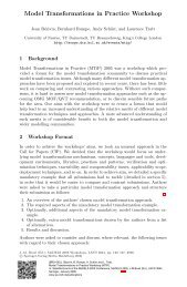
Figure 4. <strong>View</strong> <strong>of</strong> the automotive function net<br />
describing the braking system and its environment<br />
Block diagrams can be used to model a complete<br />
automotive system. For organizational reasons the diagram<br />
can be split such that many orthogonal diagrams<br />
exist which describe the system in a readable<br />
size. Additional information for the blocks and signals<br />
can be stored efficiently in a database to allow<br />
queries about the stored information.<br />
3.2 SysML block diagrams for feature views<br />
The block diagrams can also be used to describe<br />
the functions needed to realize a feature <strong>of</strong> the system.<br />
In contrast to the already mentioned hierarchical<br />
modeling <strong>of</strong> the automotive system, blocks may occur<br />
in multiple diagrams. In addition to the already<br />
described elements <strong>of</strong> the SysML block diagram we<br />
provide extensions for modeling the physical environment<br />
<strong>of</strong> the electronic system. In discussions with<br />
developers <strong>of</strong> such systems it turned up that it is extremely<br />
helpful for the understanding <strong>of</strong> the system to<br />
include additional elements. By this approach complete<br />
closed loop controllers can be modeled instead<br />
<strong>of</strong> just considering the control part. We represented<br />
surrounding elements as ordinary blocks (marked by<br />
a special stereotype ) and non-signal communication<br />
by ports with a stereotype stating the type<br />
<strong>of</strong> communication like electric or hydraulic. Figure 4<br />
shows a block diagram that represents a view <strong>of</strong> the<br />
diagram shown in Figure 3. The same elements like in<br />
the block diagram occur and elements <strong>of</strong> the environment<br />
are added to simplify the understanding <strong>of</strong> the<br />
feature.<br />
The two described notations can be checked for<br />
consistency. The detailed relation between block diagrams<br />
and views is given by the following list <strong>of</strong> context<br />
conditions that must hold:<br />
• Each block in a view not marked with a stereo-<br />
4