View-Based Modeling of Function Nets - Software Engineering
View-Based Modeling of Function Nets - Software Engineering
View-Based Modeling of Function Nets - Software Engineering

Create successful ePaper yourself
Turn your PDF publications into a flip-book with our unique Google optimized e-Paper software.
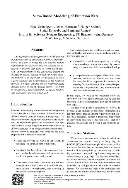
<strong>View</strong>-<strong>Based</strong> <strong>Modeling</strong> <strong>of</strong> <strong>Function</strong> <strong>Nets</strong><br />
Hans Grönniger 1 , Jochen Hartmann 2 , Holger Krahn 1 ,<br />
Stefan Kriebel 2 , and Bernhard Rumpe 1<br />
1 Institut für S<strong>of</strong>tware Systems <strong>Engineering</strong>, TU Braunschweig, Germany<br />
2 BMW Group, München, Germany<br />
Abstract<br />
This paper presents an approach to model features<br />
and function nets <strong>of</strong> automotive systems comprehensively.<br />
In order to bridge the gap between feature<br />
requirements and function nets, we describe an approach<br />
to describe both using a SysML-based notation.<br />
If requirements on the automotive system are<br />
changed by several developers responsible for different<br />
features, it is important for developers to have<br />
a good overview and understanding <strong>of</strong> the functions<br />
affected. We show that this can be comprehensively<br />
modeled using so called “feature views”. In order<br />
to validate these views against the complete function<br />
nets, consistency checks are provided.<br />
1. Introduction<br />
The task <strong>of</strong> developing automotive embedded systems<br />
is complex since a large number <strong>of</strong> functions from<br />
different vehicle domains interact in many ways. To<br />
master this complexity, system descriptions are necessary<br />
that support the process <strong>of</strong> developing such systems<br />
and that bridge the gap between requirements <strong>of</strong><br />
different features to an integrated function net architecture.<br />
However, problems with notations and tools<br />
proposed or used today <strong>of</strong>ten exist:<br />
• Tools that provide full views <strong>of</strong> the system do<br />
not scale to a large amount <strong>of</strong> functions.<br />
• Notations that have their roots in computer science<br />
are likely to be not accepted by users with<br />
a different pr<strong>of</strong>essional background.<br />
• Time-constraints make it economically not reasonable<br />
to establish a new tool in the development<br />
process if re-engineering or re-modeling <strong>of</strong><br />
the whole system is required.<br />
Our contribution to the problem <strong>of</strong> modeling complex<br />
embedded automotive systems is thus guided by<br />
the following goals:<br />
• It should be possible to integrate the modeling<br />
notation and supporting tools seamlessly into existing<br />
processes with little overhead for developers.<br />
• A comprehensible description <strong>of</strong> functions, their<br />
structure, behavior and interactions with other<br />
functions should be supported. In particular, interesting<br />
functional interrelations should be presentable<br />
in a way such that they are comprehensible<br />
for all developers involved.<br />
In this paper, we focus on the structural issues and<br />
show how our view-based approach can be used for<br />
modeling logical architectures, also called function<br />
nets in [13].<br />
The rest <strong>of</strong> the paper is structured as follows. In<br />
Section 2 the problem <strong>of</strong> modeling comprehensible<br />
function nets is detailed and the requirements for a solution<br />
are presented. Section 3 describes our approach<br />
to view-based modeling <strong>of</strong> function nets. Section 4<br />
presents related work and Section 5 concludes the paper.<br />
2. Problem Statement<br />
We assume a development process in which requirements<br />
are captured mainly textually (e.g., in<br />
DOORS [12]) by different people who are responsible<br />
for certain features. We use the term feature to denote<br />
functionalities perceptible by customers (e.g. a braking<br />
system) as common in requirements engineering /<br />
domain analysis (e.g., [3]). The features are realized<br />
by several functions which cooperate to achieve the<br />
desired functionality. The functions themselves may<br />
be needed by multiple features within the automotive<br />
system. For instance, the logic <strong>of</strong> the braking system<br />
is used by the normal brake employed by the driver<br />
[GHK+07] H. Grönniger, J. Hartmann, H. Krahn, S. Kriebel, B. Rumpe.<br />
<strong>View</strong>-<strong>Based</strong> <strong>Modeling</strong> <strong>of</strong> <strong>Function</strong> <strong>Nets</strong>.<br />
In: Proceedings <strong>of</strong> the Object-oriented Modelling <strong>of</strong> Embedded Real-Time Systems (OMER4) Workshop,<br />
Paderborn, October 2007<br />
www.se-rwth.de/publications
ut also by safety or comfort systems like the adaptive<br />
cruise control.<br />
The step from requirements to the actual realization<br />
<strong>of</strong> the system is a complex step that involves a lot<br />
<strong>of</strong> engineering work and coordination between different<br />
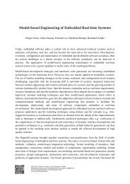
developers. Automotive architectures have been<br />
proposed to break down the complexity into manageable<br />
tasks on each architectural layer [2]. An example<br />
is shown in Fig. 1 in which requirements for all<br />
features are transformed into a function net that describes<br />
interacting logical functions that cooperatively<br />
fulfill all the requirements. In the s<strong>of</strong>tware architecture,<br />
logical functions are aggregated or split into deployable<br />
units and detailed signal or function definitions,<br />
e.g., exact data types and value ranges are provided.<br />
On this architectural layer and below the AU-<br />
TOSAR methodology can be applied [1]. The s<strong>of</strong>tware<br />
architecture is then mapped to a technical architecture<br />
consisting <strong>of</strong> ECUs and busses. S<strong>of</strong>tware and<br />
technical architecture constitute the basis for a concrete<br />
realization <strong>of</strong> the final automotive system. In this<br />
paper, we concentrate on the transition from requirements<br />
to function nets.<br />
The automotive system can be seen from two distinct<br />
viewpoints that both describe functions and their<br />
communication:<br />
Feature viewpoint. A set <strong>of</strong> diagrams describes a<br />
single feature. One feature is usually treated separately<br />
from others in the requirements analysis<br />
phases and is realized by one or more functions.<br />
Logical viewpoint. A set <strong>of</strong> diagrams describes a<br />
function and its hierarchical composition in form<br />
<strong>of</strong> an internal structure. The different functions<br />
may be realized on different ECUs and are therefore<br />
developed separately. Nevertheless, they<br />
must cooperate to achieve the common task.<br />
When developing a notation that supports modeling<br />
these viewpoints comprehensibly, we have to keep<br />
in mind that the development process involves many<br />
people with different pr<strong>of</strong>essional backgrounds (like<br />
computer science and engineering) that all need to be<br />
able to use the notation. Further, developing a modeling<br />
language should not be done from scratch but<br />
should be in line with existing standards and reuse<br />
ideas from other works.<br />
Since there is no traceable connection from requirements<br />
to nets <strong>of</strong> logical functions in which the<br />
functionality <strong>of</strong> a feature is not explicitly conceivable,<br />
the development involves extensive re-engineering<br />
when the requirements change.<br />
These observations lead us to the following problem<br />
statement:<br />
a) Which notation is most appropriate, given the<br />
context and the intended use?<br />
b) How can we model the feature requirements<br />
such that the effect <strong>of</strong> changes can easily be analyzed<br />
in the function net?<br />
Figure 1. Complex step from requirements to<br />
system realization<br />
The development is furthermore not being done<br />
from scratch but based on previous models, so a<br />
complete system from an earlier product line is already<br />
available. Typically, in the development <strong>of</strong> the<br />
next product line, changed requirements from various<br />
developers concerning new functions, function redesigns,<br />
or enhancements arise. However, many features<br />
that were present in the previous system will be<br />
reused (maybe in an enhanced version) in the next development<br />
cycle. This calls for a possibility to reuse<br />
functionality on the feature level.<br />
3. Proposed Solution<br />
The demand for models that provide an overview<br />
<strong>of</strong> functions and their interactions on a more abstract<br />
level (logical architecture) than on the s<strong>of</strong>tware and<br />
technical architecture level has also been stressed,<br />
e.g., in [13, 14]. We denote this logical architecture<br />
as function net models.<br />
One standard technique to model complex systems<br />
in a comprehensible way is to use hierarchical models.<br />
This is certainly also appropriate for function nets<br />
since it allows us to model composite logical functions<br />
as a black-box and provide refinements <strong>of</strong> those functions<br />
that model their inner structure in more detail.<br />
As explained above, especially the transition from<br />
the requirements to the function net is complex, because<br />
decisions about how a feature is realized and<br />
2
how distinct features use the same functions have to be<br />
made at the same time. Therefore we propose that it<br />
is useful to model each feature by a separate function<br />
net. These function nets explain how the feature can<br />
be realized. Then the functions <strong>of</strong> this feature function<br />
net can be related to the functions <strong>of</strong> the automotive<br />
function net describing the whole automotive system.<br />
<strong>Modeling</strong> features as function nets that already<br />
represent parts <strong>of</strong> a possible logical architecture (w.r.t.<br />
notation and used concepts like functions and signals)<br />
helps to reduce the transition complexity because the<br />
conceptual distance between requirements and logical<br />
architecture is reduced. In addition the tasks <strong>of</strong> realizing<br />
the features as functions and the embedding <strong>of</strong><br />
these functions into the whole automotive function net<br />
are now separate steps within the development process.<br />
This helps the developer to focus on a certain<br />
aspect at a time.<br />
A complete function net model <strong>of</strong> the whole system<br />
may either be to complex to understand or be described<br />
on a too abstract level to be useful. We believe<br />
that modeling function nets for features is preferably<br />
done such that the model shows a complete definition<br />
<strong>of</strong> the logical feature <strong>of</strong> interest in addition with<br />
parts <strong>of</strong> other connected features on arbitrary hierarchy<br />
levels. Consequently, our solution supports crosshierarchy<br />
views <strong>of</strong> function nets. Allowing arbitrary<br />
views <strong>of</strong> the system requires consistency checks that<br />
verify that the modeled view still conforms to the actual<br />
underlying system.<br />
The different feature views on the system could be<br />
used to create the automotive function net by merging<br />
them. Techniques from requirements engineering<br />
research (e.g. [10]) might be used to create the automotive<br />
function net. The main problem in these approaches<br />
is that the views evolve during the design<br />
process and the merging process has to be re-applied<br />
partially, obeying prior results. We also doubt that<br />
theses approaches scale to large system and decided<br />
therefore against automatic function net merging. Our<br />
approach is restricted to checking for consistency but<br />
helps the developer to detect inconsistencies. The resolution<br />
has to be applied manually.<br />
As the complexity <strong>of</strong> automotive systems steadily<br />
increases, it is no longer economically reasonable to<br />
develop such systems from scratch. The reuse <strong>of</strong> s<strong>of</strong>tware<br />
is enabled by standardizing the s<strong>of</strong>tware architecture<br />
by the AUTOSAR consortium [1] and therefore<br />
enables the development <strong>of</strong> reusable s<strong>of</strong>tware<br />
components. But the effort in the development <strong>of</strong> an<br />
automotive system does not rely at most on the implementation<br />
part but also on developing the requirements.<br />
Therefore the proposed method allows the development<br />
<strong>of</strong> the requirements <strong>of</strong> the feature separately<br />
and also their modular redesign or substitution<br />
when shifting to the next car generation. The attached<br />
functions nets describing a single feature can then be<br />
checked against the evolved automotive function net.<br />
The approach is illustrated in Figure 2.<br />
Figure 2. Intermediate views to simplify transition<br />
from requirements to function nets<br />
3.1 SysML block diagrams<br />
In [8] one <strong>of</strong> the authors investigated the use <strong>of</strong><br />
UML and enhancements as an architecture description<br />
language. One <strong>of</strong> the results was that especially<br />
a hierarchical component-based notation was missing<br />
at that time. In [9] the use <strong>of</strong> UML-RT [11] is<br />
investigated for embedded real-time systems in general,<br />
whereas other previous work [13] has shown that<br />
function nets can be modeled with UML-RT. It is outlined<br />
that UML 2.0 [5] and SysML [6] are good candidates<br />
for substituting UML-RT.<br />
Therefore we investigated among other notations<br />
the suitability <strong>of</strong> UML 2.0 and SysML for function<br />
net modeling. Our investigation showed that SysML<br />
block diagrams can be favored over UML composite<br />
structures, because they allow a more concise representation<br />
<strong>of</strong> systems. The detailed reasons are the following:<br />
• SysML requires no strict two layered modeling<br />
like in the UML where each structured class consists<br />
<strong>of</strong> parts that in turn have no internal structure.<br />
• SysML block diagrams allow modeling communication<br />
across multiple hierarchy layers without<br />
3
Figure 3. Excerpt from an automotive function<br />
net (Signals are omitted to enhance the<br />
readability)<br />
the explicit use <strong>of</strong> port delegation.<br />
• A SysML block abstracts from the strict instance/type<br />
division <strong>of</strong> the UML which complicates<br />
modeling architectures effectively.<br />
• SysML distinguishes between the form <strong>of</strong> a diagram<br />
and its use. This was extremely helpful (as<br />
later shown) when we wanted to use the same<br />
diagram type with a different semantics.<br />
The described port-delegation and the strict instance/type<br />
division originate from the modeling <strong>of</strong><br />
object-oriented s<strong>of</strong>tware, where each class is a point<br />
<strong>of</strong> variation. In modeling logical architectures this is<br />
not always the case as blocks might also be used to<br />
group subsystems which are not meant for separate<br />
reuse. SysML allows us to introduce types and therefore<br />
a reuse <strong>of</strong> subsystems where needed, in contrast<br />
to the UML which assumes constant reuse in all cases.<br />
SysML block diagrams can be used by modeling<br />
functions <strong>of</strong> an automotive system as blocks. These<br />
blocks can be hierarchical decomposed into subblocks<br />
that define the internal structure. Blocks can be connected<br />
to each other via directed connectors that represent<br />
a communication relationship. The connector<br />
can be used across the block hierarchy but also ports<br />
can be used to describe a well-defined interface. To<br />
increase the reuse, blocks can optionally have a type<br />
that allows the multiple instantiation <strong>of</strong> a single block<br />
within a diagram. Figure 3 shows an example <strong>of</strong> such<br />
a diagram. Please note that for space reasons it is not<br />
complete in the sense that it contains all possible information<br />
nor describes a representative subset <strong>of</strong> an<br />
automotive subsystem.<br />
Figure 4. <strong>View</strong> <strong>of</strong> the automotive function net<br />
describing the braking system and its environment<br />
Block diagrams can be used to model a complete<br />
automotive system. For organizational reasons the diagram<br />
can be split such that many orthogonal diagrams<br />
exist which describe the system in a readable<br />
size. Additional information for the blocks and signals<br />
can be stored efficiently in a database to allow<br />
queries about the stored information.<br />
3.2 SysML block diagrams for feature views<br />
The block diagrams can also be used to describe<br />
the functions needed to realize a feature <strong>of</strong> the system.<br />
In contrast to the already mentioned hierarchical<br />
modeling <strong>of</strong> the automotive system, blocks may occur<br />
in multiple diagrams. In addition to the already<br />
described elements <strong>of</strong> the SysML block diagram we<br />
provide extensions for modeling the physical environment<br />
<strong>of</strong> the electronic system. In discussions with<br />
developers <strong>of</strong> such systems it turned up that it is extremely<br />
helpful for the understanding <strong>of</strong> the system to<br />
include additional elements. By this approach complete<br />
closed loop controllers can be modeled instead<br />
<strong>of</strong> just considering the control part. We represented<br />
surrounding elements as ordinary blocks (marked by<br />
a special stereotype ) and non-signal communication<br />
by ports with a stereotype stating the type<br />
<strong>of</strong> communication like electric or hydraulic. Figure 4<br />
shows a block diagram that represents a view <strong>of</strong> the<br />
diagram shown in Figure 3. The same elements like in<br />
the block diagram occur and elements <strong>of</strong> the environment<br />
are added to simplify the understanding <strong>of</strong> the<br />
feature.<br />
The two described notations can be checked for<br />
consistency. The detailed relation between block diagrams<br />
and views is given by the following list <strong>of</strong> context<br />
conditions that must hold:<br />
• Each block in a view not marked with a stereo-<br />
4
type must be part <strong>of</strong> the logical architecture<br />
in the block diagram.<br />
• A hierarchy indicated in a view must be present<br />
in the logical architecture (although intermediate<br />
blocks may be left out).<br />
• Communication relationships shown in a view<br />
must be present in the logical architecture. If the<br />
view indicates that certain signals are involved<br />
in a communication they must be stated in the<br />
architecture. If no signal is attached to a communication<br />
link in a view at least one signal must be<br />
present in the architecture. A communication relationship<br />
needs not be drawn to the exact target,<br />
also any superblock is sufficient.<br />
4. Related Work<br />
In [13] function net modeling with the UML-RT<br />
is described. We extended this approach by using the<br />
SysML for modeling function nets and explained its<br />
advantages. We supplement the approach by views<br />
that simplify the transition from requirements to early<br />
design phases.<br />
In [10] view merging in the presence <strong>of</strong> incompleteness<br />
and inconsistency is described. The merging<br />
algorithm also simplifies the transition from requirements<br />
to early design phases like our approach.<br />
Especially the constant evolution <strong>of</strong> requirements during<br />
the development makes it difficult to apply such<br />
algorithms to our problem.<br />
In [7, 15] service oriented modeling <strong>of</strong> automotive<br />
systems is explained. The service layer is similar to<br />
the modeling <strong>of</strong> features. In addition we explored how<br />
services can benefit from modeling the environment<br />
together with the feature.<br />
In [4] the use <strong>of</strong> rich components is explained<br />
that employ a complex interface description including<br />
non-functional characteristics. In contrast to our<br />
approach rich components focus less on the seamless<br />
transition from requirements to function nets but assume<br />
an established predefined partitioning in components.<br />
The AUTOSAR consortium [1] standardizes the<br />
s<strong>of</strong>tware architecture <strong>of</strong> automotive system and allows<br />
the development <strong>of</strong> interchangeable s<strong>of</strong>tware components.<br />
One main problem <strong>of</strong> this approach is that s<strong>of</strong>tware<br />
architectures are too detailed in early development<br />
phases where functions nets are commonly accepted<br />
by developers.<br />
5. Conclusion<br />
In this paper we propose an approach to use block<br />
diagrams as provided by SysML to model individual<br />
vehicle functionalities, so called “features” <strong>of</strong> an automotive<br />
system and complete function nets using a<br />
similar notation. This similarity simplifies the seamless<br />
transition from stating the requirements to designing<br />
the system and reduces the necessary effort for<br />
feedback loops in the development cycle. It also allows<br />
switching viewpoints between feature-oriented<br />
requirements and function net architecture more easily.<br />
A drawback <strong>of</strong> our approach might be the introduction<br />
<strong>of</strong> an additional modeling layer for views. While<br />
the results <strong>of</strong> smaller case-studies are promising, a detailed<br />
evaluation <strong>of</strong> the method with an example <strong>of</strong><br />
realistic size still needs to be carried out.<br />
The approach described in this paper focuses on<br />
structural aspects. We already identified timing properties<br />
and other physical requirements and constraints<br />
that will be annotated to both the function nets and<br />
their according views. Timing constraints are a special<br />
form <strong>of</strong> requirements that shall be expressed in the<br />
feature diagrams. For the function net the actual execution<br />
times <strong>of</strong> an implementation may be derived by<br />
formal analysis or measuring representative runs. In<br />
the future we will further explore consistency checks<br />
that can be derived from these two types <strong>of</strong> timing<br />
properties.<br />
References<br />
[1] Autosar website http://www.autosar.org.<br />
[2] Manfred Broy. Challenges in automotive s<strong>of</strong>tware engineering.<br />
In Proceedings <strong>of</strong> ICSE 2006, 2006.<br />
[3] Krzyszt<strong>of</strong> Czarnecki and Ulrich W. Eisenecker. Generative<br />
Programming: Methods, Tools, and Applications.<br />
Addison-Wesley, 2000.<br />
[4] Werner Damm, Angelika Votintseva, Alexander Metzner,<br />
Bernhard Josko, Thomas Peikenkamp, and<br />
Eckard Böde. Boosting re-use <strong>of</strong> embedded automotive<br />
applications through rich components. In Proceedings<br />
<strong>of</strong> Foundations <strong>of</strong> Interface Technologies 2005, 2005.<br />
[5] Object Management Group. Unified modeling language:<br />
Superstructure version 2.0 (05-07-04), August<br />
2005. http://www.omg.org/docs/formal/05-07-04.pdf.<br />
[6] Object Management Group. Sysml specification<br />
version 1.0 (2006-05-03), August 2006.<br />
http://www.omg.org/docs/ptc/06-05-04.pdf.<br />
[7] S. Rittmann, A. Fleischmann, J. Hartmann, C. Pfaller,<br />
M. Rappl, and D. Wild. Integrating service specifications<br />
at different levels <strong>of</strong> abstraction. In SOSE<br />
’05: Proceedings <strong>of</strong> the IEEE International Workshop,<br />
pages 71–78, Washington, DC, USA, 2005. IEEE<br />
Computer Society.<br />
5
[8] B. Rumpe, M. Schoenmakers, A. Radermacher, and<br />
A. Schürr. Uml + room as a standard adl? In<br />
F. Titsworth, editor, <strong>Engineering</strong> <strong>of</strong> Complex Computer<br />
Systems, ICECCS’99 Proceedings. IEEE Computer<br />
Society, 1999.<br />
[9] Bernhard Rumpe and Robert Sandner. Uml - unified<br />
modeling language im einsatz. teil 3. uml-rt für<br />
echtzeitkritische und eingebettete systeme. at - Automatisierungstechnik,<br />
Reihe Theorie für den Anwender,<br />
11/2001, (11), 2001.<br />
[10] Mehrdad Sabetzadeh and Steve Easterbrook. <strong>View</strong><br />
merging in the presence <strong>of</strong> incompleteness and inconsistency.<br />
Requir. Eng., 11(3):174–193, 2006.<br />
[11] Bran Selic, Garth Gullekson, and Paul T. Ward. Real-<br />
Time Object-Oriented <strong>Modeling</strong>. John Wiley & Sons,<br />
April 1994.<br />
[12] Telelogic DOORS website<br />
www.telelogic.com/products/doors/.<br />
[13] Michael von der Beeck. <strong>Function</strong> net modeling with<br />
uml-rt: Experiences from an automotive project at<br />
bmw group. In UML Satellite Activities, pages 94–104,<br />
2004.<br />
[14] Michael von der Beeck. Eigung der uml 2.0 zur entwicklung<br />
von bordnetzarchitekturen. In Tagungsband<br />
des Dagstuhl-Workshops Modellbasierte Entwicklung<br />
eingebetteter Systeme, 2006.<br />
[15] Doris Wild, Andreas Fleischmann, Judith Hartmann,<br />
Christian Pfaller, Martin Rappl, and Sabine Rittmann.<br />
An Architecture-Centric Approach towards the Construction<br />
<strong>of</strong> Dependable Automotive S<strong>of</strong>tware. In Proceedings<br />
<strong>of</strong> the SAE 2006 World Congress, 2006.<br />
6