A practical guide to earth resistance testing - Weschler Instruments
A practical guide to earth resistance testing - Weschler Instruments
A practical guide to earth resistance testing - Weschler Instruments

Create successful ePaper yourself
Turn your PDF publications into a flip-book with our unique Google optimized e-Paper software.
esistance is needed. This is where we come in with our Megger Ground<br />
Resistance Tester, a self-contained portable instrument that is reliable and<br />
easy <strong>to</strong> use. With it, you can check the <strong>resistance</strong> of your <strong>earth</strong> electrode<br />
while it is being installed; and, by periodic tests, observe any changes with<br />
time.<br />
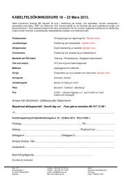
To understand the principle of <strong>earth</strong> <strong>testing</strong>, consider the schematic<br />
diagram in Fig. 10a. Bear in mind our previous observation with reference<br />
<strong>to</strong> the <strong>earth</strong> shell diagram in Fig. 9: with increased distance from an<br />
(a)<br />
(b)<br />
electrode, the <strong>earth</strong> shells are of greater surface area and therefore of<br />
lower <strong>resistance</strong>. Now, assume that you have three rods driven in<strong>to</strong> the<br />
<strong>earth</strong> some distance apart and a voltage applied, as shown in Fig. 10a.<br />
The current between rods 1 and 2 is measured by an ammeter; the<br />
potential difference (voltage) between rods 1 and 3 is measured by a<br />
voltmeter.<br />
If rod 3 is located at various points between rods 1 and 2, preferably in a<br />
straight line 7 , you can get a series of voltage readings. By Ohm’s Law<br />
(R = E/I) you can determine the <strong>earth</strong> <strong>resistance</strong> at any point measured.<br />
For example, if the measured voltage E between rods 1 and 3 is 30 V and<br />
the measured current I is 2 A, the <strong>resistance</strong> of the <strong>earth</strong> R at that point<br />
would be 15 Ω.<br />
The series of <strong>resistance</strong> values can be plotted against distance <strong>to</strong> obtain<br />
a curve (Fig. 10b). Note that as rod 3 is moved away from rod 1, the<br />
<strong>resistance</strong> values increase, but the amount of increase gets less and less<br />
until a point is reached where the rate of increase becomes so small that<br />
I can almost be considered constant (20 Ω in Fig. 10b). The <strong>earth</strong> shells<br />
between the two rods (1 and 3) have so great a surface area that they add<br />
little <strong>to</strong> the <strong>to</strong>tal <strong>resistance</strong>. Beyond this point, as rod 3 approaches the<br />
<strong>earth</strong> shells of rod 2, <strong>resistance</strong> gradually picks up. Near rod 2, the values<br />
rise sharply.<br />
Now, let’s say that rod 1 is our <strong>earth</strong> electrode under test. From a typical<br />
<strong>earth</strong>-<strong>resistance</strong> curve, such as Fig. 10b, what is the <strong>resistance</strong> <strong>to</strong> <strong>earth</strong> of<br />
this rod? We call rod 2 current-reference probe C and rod 3, potentialreference<br />
probe P (simply for convenience in identification). The correct<br />
<strong>resistance</strong> is usually obtained if P (rod 3) is placed at a distance from the<br />
center of the <strong>earth</strong> electrode (rod 1) about 62 percent of the distance<br />
between the <strong>earth</strong> electrode and C (rod 2).<br />
For example, in Fig. 10b, the distance D from the <strong>earth</strong> electrode <strong>to</strong> C is<br />
100 ft. Taking 62 percent of this distance, we get 62 ft. From Fig. 10b,<br />
Fig. 10: Principle of an <strong>earth</strong> <strong>resistance</strong> test<br />
7 Actually, current can exist in other paths between the two fixed electrodes, so that rod 3<br />
could be (and might have <strong>to</strong> be) located at other than along a straight line.<br />
24 1-866-254-0962 www.megger.com Getting Down <strong>to</strong> Earth 25