motor control - Semikron
motor control - Semikron
motor control - Semikron

You also want an ePaper? Increase the reach of your titles
YUMPU automatically turns print PDFs into web optimized ePapers that Google loves.
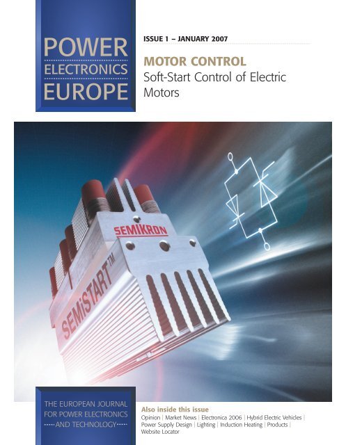
ISSUE 1 – JANUARY 2007<br />
MOTOR CONTROL<br />
Soft-Start Control of Electric<br />
Motors<br />
Also inside this issue<br />
Opinion | Market News | Electronica 2006 | Hybrid Electric Vehicles |<br />
Power Supply Design | Lighting | Induction Heating | Products |<br />
Website Locator
26 MOTOR CONTROL www.semikron.com<br />
Soft-Start Control of Electric<br />
Motors<br />
For a three-phase induction <strong>motor</strong> direct on-line start involves a very high <strong>motor</strong> starting torque and a very<br />
high starting current. Semiconductors in soft-start devices must be extremely robust to resist considerable<br />
chip temperature changes and must demonstrate very good load cycle capability. The antiparallel thyristor<br />
module SEMISTART for soft-starters provides half the internal thermal impedance of conventional<br />
components, thanks to double-sided thyristor chip cooling and thus, ensures high over-current capability for<br />
the starting period. Norbert Schäfer and Ralf Herrmann, SEMIKRON, Nuremberg, Germany<br />
The anti-parallel thyristor module<br />
SEMiSTART (Figure 1), designed<br />
specifically for use in soft-start devices,<br />
provides half the internal thermal<br />
impedance of conventional components<br />
in modular designs, thanks to doublesided<br />
thyristor chip cooling. This compact<br />
module also uses proven pressure contact<br />
technology.<br />
In practice, three different types of<br />
<strong>motor</strong> starter <strong>control</strong> are used which are<br />
described in the following.<br />
Figure 1: The anti-parallel<br />
thyristor module SEMiSTART<br />
is designed specifically for use<br />
in soft-start devices<br />
Direct on-line starters<br />
For a three-phase induction <strong>motor</strong><br />
(asynchronous <strong>motor</strong>), direct on-line start<br />
involves a very high <strong>motor</strong> starting torque<br />
and a very high starting current. The high<br />
<strong>motor</strong> starting torque can lead to<br />
mechanical damage; for instance, the<br />
conveyor belt driven by the three-phase<br />
induction <strong>motor</strong> may tear. The high<br />
starting current can also result in voltage<br />
spikes in the grid. The larger the <strong>motor</strong>,<br />
the more serious the effects.<br />
To combat such undesired effects, the<br />
voltage applied to the induction <strong>motor</strong><br />
during the start-up phase is <strong>control</strong>led.<br />
This means that the starting current and,<br />
consequently, the starting torque can be<br />
limited (see Figure 2).<br />
Figure 2:<br />
Motor current<br />
at direct<br />
on-line start<br />
and with soft<br />
start<br />
Star-delta starters<br />
A simple solution is the star-delta starter<br />
(also known as the wye-delta starter).<br />
Here, the <strong>motor</strong> stator windings are<br />
connected in star (or wye) connection as<br />
the <strong>motor</strong> accelerates up to its running<br />
speed; once the <strong>motor</strong> reaches near rated<br />
speed, the windings are connected in<br />
delta. The effect of starting in star<br />
connection is that the voltage across each<br />
stator winding during the build-up to<br />
normal running speed is 1/3 of the<br />
normal. The changeover from star to delta<br />
connection is normally done using a<br />
mechanical contactor. As, however, there<br />
are only 2 switch connections (star and<br />
delta), ‘<strong>control</strong>ling’ is not a particularly<br />
appropriate term in this case. Moreover,<br />
this type of starter ‘<strong>control</strong>’ is not lowmaintenance,<br />
as the mechanical<br />
contactors are prone to wear caused by<br />
sparking and need to be replaced.<br />
Soft-starters<br />
To <strong>control</strong> the voltage applied to the<br />
induction <strong>motor</strong> during the start-up phase,<br />
a soft-start device (soft starter), is needed.<br />
Issue 1 2007<br />
Power Electronics Europe
28 MOTOR CONTROL www.semikron.com<br />
Figure 3: Principle schematic of a soft starter<br />
In soft starters, thyristors are used for<br />
voltage <strong>control</strong> (see Figure 3).<br />
Two anti-parallel thyristors are<br />
connected in series between the <strong>motor</strong><br />
windings and the grid. During the run-up<br />
to normal running speed (ramp-up), the<br />
voltage across the <strong>motor</strong> windings is then<br />
<strong>control</strong>led by way of phase <strong>control</strong>.<br />
Depending on when the thyristors are<br />
fired (trigger delay angle a), this means<br />
that the starting torque and the starting<br />
current can be set to desired values. A<br />
further advantage of soft-start <strong>control</strong> is<br />
that the starting time can also be<br />
<strong>control</strong>led.<br />
The current flowing through the<br />
thyristors produces power dissipation in<br />
the semiconductors. This power<br />
dissipation heats up the semiconductors,<br />
which then have to be cooled. To prevent<br />
further power dissipation in the<br />
semiconductors after the ramp-up phase,<br />
the semiconductors are bypassed by a<br />
mechanical switch (mechanical<br />
contactor). This bypass switch can be<br />
relatively small since it does not have to<br />
switch large loads. A further plus is that<br />
the contacts of the bypass switch do not<br />
‘burn’ down. As the system has already<br />
reached normal running speed, no large<br />
voltage drop that has to be switched by<br />
the contacts of the bypass switch occurs.<br />
The only voltage drop is that resulting<br />
from the mechanical design and that<br />
across the fired thyristors. This means<br />
that no large loads are being switched,<br />
which is why soft-starters are lowmaintenance<br />
devices.<br />
times higher). In large-scale systems,<br />
the peak starting current is often<br />
several thousand amperes. The<br />
semiconductors used therefore have to<br />
be able to carry this high starting<br />
current during the start phase. At the<br />
same time, however, the soft-starter<br />
must be cost-optimised and as compact<br />
as possible. For this reason, the<br />
semiconductors used (including<br />
heatsink) must be as small as possible.<br />
Thus, for reasons of cost, thyristor<br />
components whose rated current is far<br />
lower than the large system starting<br />
current are used in practice. This is why<br />
the thyristor chips heat up substantially<br />
during the brief start phase, e.g. from TStart<br />
= 40°C to TRamp-up = 130°C, resulting in a<br />
chip temperature difference of 90K. If a<br />
system is switched on 3 times per hour,<br />
8 hours a day on 365 days a year, the<br />
total number of load changes after 10<br />
years is 87,600. These thyristors must be<br />
able to carry the overload current that<br />
occurs during the start phase for<br />
decades.<br />
Up till now, manufacturers of softstarters<br />
have had difficulties in finding<br />
the optimum semiconductors for their<br />
devices on the market. This is where<br />
the anti-parallel thyristor module<br />
SEMiSTART steps in, as this module was<br />
developed specifically for use in softstart<br />
devices.<br />
Mounting and connecting technology<br />
There are a number of different ways<br />
of assembling and connecting a silicon<br />
chip. In many modules, the silicon chip is<br />
soldered on both sides (anode and<br />
cathode side) with single-sided module<br />
cooling (see Figure 4).<br />
The heat that builds up in the module<br />
is dissipated to the heatsink via the<br />
baseplate (single-sided cooling). A<br />
particular problem here is the different<br />
thermal expansion coefficients of the<br />
individual components used in a thyristor<br />
module. In modules with soldered<br />
connections, the thyristor chip, solder<br />
and copper (main terminals) have<br />
different expansion coefficients.<br />
Over time, these different coefficients<br />
lead to fatigue in the solder that<br />
connects the chip and the copper<br />
terminal due to load cycle operation. As<br />
a result, delamination of the solder layer<br />
occurs, i.e. fine hairline cracks appear in<br />
the solder layer. The solder fatigue<br />
cracking then results in an increase in<br />
thermal impedance which, in turn, leads<br />
to an increase in chip temperature and,<br />
ultimately chip failure. In fact, it is not<br />
unusual for chip failure to occur in<br />
soldered modules.<br />
In modules based on pressure contact<br />
technology, by way of contrast, the chip<br />
is connected between the main<br />
terminals by contact pressure. In these<br />
modules, the chip is not soldered<br />
between the main terminals. Instead,<br />
very high contact pressure (several kN)<br />
is applied to ‘retain’ the chip between<br />
the main terminals. In practice it has<br />
been shown that, especially in<br />
applications with large power loads<br />
Semiconductor requirements<br />
To ensure that a soft-starter is both<br />
compact and cost-efficient without<br />
compromising reliability, the<br />
semiconductors used in a soft-starter<br />
must meet a number of important<br />
requirements.<br />
Even when a soft-starter is used the<br />
starting current during the starting<br />
phase of a drive system is still several<br />
times larger than the rated current (3-5<br />
Figure 4: Principle<br />
behind the solder<br />
contact module<br />
Issue 1 2007<br />
Power Electronics Europe
www.semikron.com MOTOR CONTROL 29<br />
(rated currents >200A), the load cycle<br />
capability of the components connected<br />
using pressure contact technology is far<br />
superior owing to the non-use of<br />
soldered connections.<br />
This is why <strong>Semikron</strong> recommends<br />
using pressure-contacted components in<br />
soft-start devices with larger rated<br />
currents. And it is this very pressure<br />
contact technology that is used in<br />
SEMiSTART (see Figure 5).<br />
In SEMiSTART modules the two thyristor<br />
chips are ‘pressed’ between two<br />
heatsinks.<br />
This type of mounting and connection<br />
does not contain solder layers, which is<br />
Figure 5: Pressure<br />
contact technology<br />
used in the<br />
SEMiSTART module<br />
why the SEMiSTART modules boast very<br />
good load cycle capability and,<br />
consequently, a long service life.<br />
The heatsinks are optimally<br />
dimensioned for the chip dimensions and<br />
for use in soft-start devices. The result is<br />
very compact modules. The total thermal<br />
resistance between the thyristor chips and<br />
heatsink is far lower than that of other<br />
conventional components. As the chips<br />
are pressed directly between two<br />
heatsinks and are cooled on both sides,<br />
the thermal resistances are very low.<br />
Another advantage is that very little<br />
mounting effort is necessary for<br />
SEMiSTART modules: no special clamps<br />
are needed as is the case when<br />
assembling capsule thyristors. Plus, no<br />
thermal paste is needed as in the case of<br />
module assembly.<br />
SEMiSTART modules can, of course,<br />
also be used in other applications, e.g.<br />
protective circuits. SEMiSTART modules<br />
come in three different sizes and a total<br />
of 5 different current classes. The<br />
current range is 500A – 3000A for a<br />
maximum current flow time (ramp-up<br />
time) of 20 seconds. The thyristors<br />
have a maximum off-state voltage of<br />
1800V.<br />
Conclusion<br />
The market for soft-starters will<br />
continue to grow over the coming years<br />
as the advantages that these<br />
components boast over conventional<br />
solutions become more apparent. The<br />
antiparallel thyristor module SEMISTART<br />
for soft-starters provides half the<br />
internal thermal impedance of<br />
conventional components thanks to<br />
double-sided thyristor chip cooling and<br />
its compact design. Extremely high<br />
overcurrents are therefore possible for a<br />
short period. What’s more, thanks to the<br />
use of pressure contact technology,<br />
these modules offer a high degree of<br />
reliability.<br />
PRACTICAL ENGINEER’S HANDBOOKS<br />
From the publishers of<br />
Hydraulics&<br />
Pneumatics<br />
If you would like to obtain additional copies of the handbooks, please complete<br />
the form below and either fax it on 01732 360034 or post your order to:<br />
Engineers Handbook, DFA MEDIA LTD,<br />
Cape House, 60a Priory Road, Tonbridge, Kent TN9 2BL<br />
You may also telephone your order on 01732 370340<br />
Cheques should be made payable to DFA MEDIA LTD and crossed A/C Payee.<br />
Copies of the handbooks are available at £4.99 per copy.<br />
Discounts are available for multiple copies.<br />
2-5 copies £4.30, 6-20 copies £4.10, 20+ copies £3.75.<br />
Postage and Packaging:<br />
1-3 copies £2.49 4 copies and over £3.49<br />
HYDRAULICS<br />
INDUSTRIAL<br />
MOTORS<br />
SERVOS<br />
AND STEPPERS<br />
COMPRESSED AIR<br />
PNEUMATICS<br />
INDUSTRIAL<br />
ELECTRIC DRIVES<br />
There are now 6 of these handy<br />
reference books from the publishers of<br />
the Drives & Controls and<br />
Hydraulics & Pneumatics magazines.<br />
Published in an easily readable style<br />
and designed to help answer basic<br />
questions and everyday problems<br />
without the need to refer to weighty<br />
textbooks.<br />
We believe you’ll find them invaluable<br />
items to have within arms reach.<br />
PLEASE ALLOW UPTO 28 DAYS FOR DELIVERY<br />
Name:<br />
Company Name:<br />
Address:<br />
Post Code:<br />
Tel: Total Number of Copies @ £ p+p Total £<br />
QUANTITY<br />
QUANTITY<br />
QUANTITY QUANTITY QUANTITY<br />
Drives S & S Hyd H/B Pne H/B Ind Mot Comp<br />
H/B H/B Air<br />
DFA MEDIA LTD,<br />
Cape House, 60a Priory Road, Tonbridge, Kent TN9 2BL<br />
QUANTITY