![[9] TROUBLE CODE LIST SHARP TROUBLE & ERROR ... - OlsonBros](https://img.yumpu.com/2621930/1/500x640/9-trouble-code-list-sharp-trouble-amp-error-olsonbros.jpg)
[9] TROUBLE CODE LIST SHARP TROUBLE & ERROR ... - OlsonBros
[9] TROUBLE CODE LIST SHARP TROUBLE & ERROR ... - OlsonBros
[9] TROUBLE CODE LIST SHARP TROUBLE & ERROR ... - OlsonBros

Create successful ePaper yourself
Turn your PDF publications into a flip-book with our unique Google optimized e-Paper software.
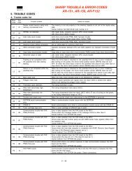
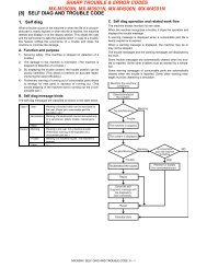
[9] <strong>TROUBLE</strong> <strong>CODE</strong> <strong>LIST</strong><br />
1. Trouble code<br />
Trouble<br />
code<br />
AR-505<br />
Content of trouble Remark<br />
Trouble<br />
detection<br />
C1 00 MC trouble PCU<br />
C2 00 TC trouble PCU<br />
E7 00 ICU communication trouble ICU<br />
01 Image data memory trouble ICU<br />
02 Laser trouble ICU<br />
03 HDD trouble ICU<br />
10 Shading trouble (Black correction) ICU<br />
11 Shading trouble (White correction) ICU<br />
13 CCD light quantity check error ICU<br />
90 ICU communication trouble PCU<br />
F1 00 Finisher communication trouble PCU<br />
01 Finisher 1 jogger shift trouble / Finisher<br />
2 alignment section abnormality<br />
FIN<br />
02 Finisher transport motor abnormality FIN<br />
03 Sorter guide bar oscillation motor<br />
trouble<br />
SOT<br />
04 Finisher 1 elevator lower limit detection /<br />
Finisher 2 stack tray lower limit detection<br />
FIN<br />
05 Finisher 1 elevator home / Finisher 2<br />
stack tray sensor abnormality<br />
FIN<br />
06 Finisher shift motor abnormality FIN<br />
08 Finisher staple shift motor trouble FIN<br />
10 Finisher staple unit operation trouble FIN<br />
11 Finisher 1 pusher motor trouble /<br />
Finisher 2 boomerang rotation<br />
abnormality<br />
FIN<br />
14 Finisher 2 stack tray abnormality FIN<br />
15 Finisher 1 elevator motor trouble /<br />
Finisher 2 stack tray motor lock<br />
FIN<br />
16 Staple sorter holding moter trouble SOT<br />
17 ST paper exit roller pressure release<br />
trouble<br />
FIN<br />
18 Tray 3 paper exit paddler operation<br />
trouble<br />
FIN<br />
50 Non-suport trouble in automatic<br />
detection of option connection (Sorter,<br />
finisher)<br />
PCU<br />
80 Finisher power not supplied FIN<br />
F2 00 Toner control sensor open PCU<br />
02 Toner motor connector unconnected PCU<br />
31 Process control trouble (OPC drum<br />
surface reflection rate abnormality)<br />
PCU<br />
32 Process control trouble (Drum marking<br />
scanning trouble)<br />
PCU<br />
37 Drum marking sensor gain adjustment<br />
error<br />
PCU<br />
39 Process thermistor breakdown PCU<br />
F3 12 Copier top stage CS lift up trouble PCU<br />
22 Copier bottom stage CS lift up trouble PCU<br />
F9 00 Printer communication trouble ICU<br />
01 PRT DRAM trouble PRT<br />
02 PRT Centroport check error PRT<br />
03 Network card trouble<br />
04 Printer program error<br />
10 PRT SCSI LSI abnormality ICU<br />
90 Printer communication trouble PRT<br />
H2 00 Thermistor open (HL1) PCU<br />
01 Thermistor open (HL2) PCU<br />
H3 00 Heat roller high temperature detection<br />
(HL1)<br />
PCU<br />
01 Heat roller high temperature detection<br />
(HL2)<br />
PCU<br />
H4 00 Heat roller low temperature detection<br />
(HL1)<br />
PCU<br />
01 Heat roller low temperature detection<br />
(HL2)<br />
PCU<br />
8/6/1999 9 – 1<br />
Trouble<br />
code<br />
Content of trouble Remark<br />
H5 01 3 continuous POD1 not-reaching JAM<br />
detection<br />
Trouble<br />
detection<br />
PCU<br />
02 Fusing thermistor abnormality PCU<br />
L1 00 Scanner feed trouble PCU<br />
L3 00 Scanner return trouble PCU<br />
L4 01 Main motor lock detection PCU<br />
L6 10 Polygon motor lock detection ICU<br />
L8 01 No full-wave signal PCU<br />
02 Full-wave signal width abnormality PCU<br />
U2 00 EEPROM read/write error ICU<br />
11 Counter check sum error (EEPROM) ICU<br />
12 Adjustment value check sum error<br />
(EEPROM)<br />
ICU<br />
U4 02 ADU alignment plate operation<br />
abnormality<br />
PCU<br />
03 ADU rear edge plate operation<br />
abnormality<br />
PCU<br />
U5 00 RADF/SPF/RSPF communication<br />
trouble<br />
PCU<br />
01 RADF resist sensor trouble RADF<br />
02 RADF eject/inversion sensor trouble RADF<br />
03 RADF timing sensor trouble RADF<br />
06 RSPF post-separation sensor trouble RSPF<br />
07 RSPF read sensor trouble RSPF<br />
08 RSPF SB sensor trouble RSPF<br />
11 RADF paper feed motor operation<br />
abnormality<br />
RADF<br />
16 RSPF fan motor operation abnormality RSPF<br />
U6 00 Desk communication trouble PCU<br />
01 Desk 1 CS lift up trouble Desk<br />
02 Desk 2 CS lift up trouble Desk<br />
03 Desk 3 CS lift up trouble Desk<br />
08 Desk 24V power abnormality Desk<br />
09 LCC lift motor trouble LCC<br />
10 Desk transport motor trouble Desk<br />
20 LCC communication trouble PCU<br />
21 LCC transport motor trouble LCC<br />
22 LCC 24V power abnormality LCC<br />
50 Non-suport trouble in automatic<br />
detection of option connection (Desk<br />
unit)<br />
PCU<br />
51 Non-suport trouble in automatic<br />
detection of option connection (LCC<br />
unit)<br />
PCU<br />
U7 00 RIC communication trouble PCU<br />
U9 00 Operation control communication<br />
trouble<br />
ICU<br />
90 Operation control communication<br />
trouble<br />
OPE<br />
EE EL Auto developing adjustment trouble<br />
(Overtoner)<br />
In SIM only PCU<br />
EU Auto developing adjustment trouble<br />
(Undertoner)<br />
In SIM only PCU<br />
FC 00 ASK/IrDA modulation LSI reset error<br />
01 ASK/IrDA switch error<br />
PC Personal counter not installed ICU<br />
PF RIC copy inhibit command<br />
reception<br />
ICU<br />
– – Auditor not ready ICU
2. Self diagnostics<br />
Trouble code<br />
Main Sub<br />
Description<br />
code code<br />
C1 00 Content MC trouble<br />
Detail Main charger output error (output<br />
released)<br />
Trouble signal from high-voltage<br />
transformer<br />
Cause Main charger improperly installed<br />
Main charger improperly assembled<br />
High-voltage transformer connector<br />
removed<br />
High-voltage harness removed or wire<br />
broken<br />
Check Check main charger output with SIM8-2.<br />
and Check main charger connector for<br />
remedy disconnection.<br />
Replace high-voltage unit.<br />
C2 00 Content TC trouble<br />
Detail Transfer charger output error (output<br />
short-circuiting)<br />
Trouble signal from high-voltage<br />
transformer<br />
Cause Transfer charger contaminated with<br />
foreign matter<br />
Transfer charger wire broken<br />
High-voltage transformer connector<br />
disconnected<br />
Check Check transfer charger output with<br />
and SIM8-6.<br />
remedy Replace high-voltage unit.<br />
E7 00 Content ICU communication trouble (ICU<br />
detection)<br />
Detail Communication setup error,<br />
framing/parity/protocol error<br />
Cause Slave unit PWB connector improper<br />
connection<br />
Slave unit PWB – ICU PWB harness<br />
trouble<br />
Connector pin breakage of the motor<br />
PWB of the slave unit PWB<br />
Slave unit ROM trouble. no ROM, ROM<br />
reverse insertion, ROM pin breakage<br />
Check Connect the connector of the slave unit<br />
and PWB and the ICU PWB.<br />
remedy Check the connection and the harness.<br />
Check the grounding of the copier.<br />
Check the ROM of the slave unit PWB.<br />
01 Content Image data memory trouble<br />
Detail The ICU image data memory (SIMM) is<br />
detected only as 8MB or less.<br />
The SIMM capacity is insufficient for the<br />
model.<br />
Cause The ICU PWB SIMM is not installed.<br />
The ICU PWB SIMM does not work<br />
properly.<br />
The ICU PWB SIMM is not installed<br />
properly.<br />
ICU PWB abnormality<br />
Check Check installation of the ICU PWB SIMM.<br />
and Check the SIMM capacity with SIM<br />
remedy 22-10.<br />
Replace the ICU PWB SIMM.<br />
AR-505<br />
Trouble code<br />
Main Sub<br />
Description<br />
code code<br />
E7 02 Content Laser trouble<br />
Detail BD signal from LSU kept at OFF or ON<br />
Cause Connector to LSU or harness inside LSU<br />
disconnected or wire broken<br />
Polygon motor improperly rotating<br />
Laser home position sensor improperly<br />
positioned inside LSU<br />
Laser power supply line does not have<br />
proper voltage<br />
Laser LED improperly lighting<br />
ICU PWB error<br />
Check Check LSU connector for disconnection.<br />
and Check LSU operation with SIM61-1.<br />
remedy Check polygon motor for rotation.<br />
Check laser LED for lighting.<br />
Replace LSU unit.<br />
Replace ICU PWB.<br />
03 Content HDD trouble<br />
Detail HDD is not recognized in the model with<br />
HDD installed.<br />
Cause The HDD is not installed to the ICU PWB.<br />
The HDD does not work properly in the<br />
ICU PWB.<br />
The HDD is not installed to the ICU PWB<br />
properly.<br />
ICU PWB abnormality<br />
Check Check installation of the HDD to the ICU<br />
and PWB.<br />
remedy Check connection of the HDD harness to<br />
the ICU.<br />
Replace the HDD.<br />
Replace the ICU PWB.<br />
10 Content Shading trouble (black correction)<br />
Detail Improper CCD black reading level for<br />
copy lamp going out<br />
Cause Improper installation of flat cable to CCD<br />
unit<br />
CCD unit error<br />
ICU PWB error<br />
Check Check flat cable to CCD unit for<br />
and installation.<br />
remedy Check CCD unit.<br />
Check ICU PWB.<br />
11 Content Shading trouble (white correction)<br />
Detail Improper CCD white reference plate<br />
reading level for copy lamp lighting<br />
Cause Improper installation of flat cable to CCD<br />
unit<br />
Mirror, lens or reference white plate<br />
contaminated<br />
Copy lamp operation error<br />
Improperly installed CCD unit<br />
CCD unit error<br />
ICD PWB error<br />
Check Clean mirror, lens, or reference white<br />
and plate.<br />
remedy Check copy lamp for light amount<br />
(SIM5-3) and lighting.<br />
Check CCD unit.<br />
Check ICU PWB.<br />
9 – 2 8/6/1999
AR-505<br />
Trouble code<br />
Main Sub<br />
Description<br />
code code<br />
E7 13 Content CCD light quantity check error<br />
Detail Copy lamp light amount adjustment in<br />
shading cannot be made<br />
Cause Copy lamp does not light (broken wire,<br />
improper installation)<br />
Improper installation of flat cable to CCD<br />
unit<br />
Improper connection of copy lamp CL<br />
lead wire<br />
Mirror, lens, or reference white plate<br />
Dirt or dew<br />
Improper output of copy lamp power<br />
supply<br />
Improper installation of CCD unit<br />
CCD unit error<br />
ICU PWB error<br />
Check Clean mirror, lens, reference white plate.<br />
and Check copy lamp for light amount<br />
remedy (SIM5-3) and lighting.<br />
Check CCD unit.<br />
Check ICU PWB.<br />
90 Content ICU communication trouble (PCU<br />
detection)<br />
Detail Communication setup<br />
error/framing/parity/protocol error<br />
Cause Slave unit PWB connector improper<br />
connection<br />
Slave unit PWB – ICU PWB harness<br />
trouble<br />
Slave unit PWB mother board connector<br />
pin breakage<br />
Check Check the slave unit PWB and the ICU<br />
and PWB connector connection.<br />
remedy Check the copier earth.<br />
F1 00 Content Finisher communication trouble<br />
Detail Communication line test error occurs<br />
when power is turned on or after the exit<br />
of a simulation mode.<br />
Improper communication with sorter<br />
Cause Improper connection or broken wire of<br />
connector or harness between copier and<br />
sorter<br />
Finisher control PWB defective<br />
Control PWB (PCU) defective<br />
Malfunction due to noise<br />
Check Clear by turning the power supply<br />
and OFF/ON.<br />
remedy Check communication line connector and<br />
harness.<br />
Replace Finisher control PWB or PCU<br />
PWB.<br />
01 Content Finisher1 jogger shift trouble / Finisher 2<br />
alignment section abnormality<br />
Detail Jogger shift trouble / Alignment plate shift<br />
trouble<br />
Cause Motor lock<br />
Motor rpm abnormality<br />
Motor overcurrent<br />
Finisher control PWB trouble<br />
Check Check the jogger motor operation with<br />
and<br />
remedy<br />
SIM 3-3.<br />
8/6/1999 9 – 3<br />
Trouble code<br />
Main Sub<br />
Description<br />
code code<br />
F1 02 Content Finisher transport motor abnormality<br />
Detail Transport motor drive trouble<br />
Cause Motor lock<br />
Check Check transport motor operation with<br />
and<br />
remedy<br />
SIM3-3.<br />
03 Content Sorter guide bar oscillation motor trouble<br />
Detail Sorter guide bar oscillation motor drive<br />
abnormality<br />
Cause Motor lock.<br />
Motor rotation abnormality.<br />
Overcurrent to motor<br />
Sorter control PWB abnormality<br />
Check Check the guide bar motor operation with<br />
and<br />
remedy<br />
SIM3-3.<br />
04 Content Finisher 1 elevator lower limit detection/<br />
Finisher 2 stack tray lower limit detection<br />
Detail When the bin is shifted, the upper limit or<br />
the lower limit sensor is detected. / The<br />
elevator exceeds the lower limit.<br />
Cause Sensor defective<br />
Sorter/finisher control PWB abnormality<br />
Check<br />
and<br />
remedy<br />
Check sensor with SIM3-2.<br />
05 Content Finisher 1 elevator home / Finisher 2<br />
stack tray sensor abnormality<br />
Detail The elevator does not detect the home<br />
position. / Stack tray sensors are turned<br />
on in the abnormal combination.<br />
Cause Sensor defective<br />
Sorter/finisher control PWB abnormality<br />
Check<br />
and<br />
remedy<br />
Check sensor with SIM3-2.<br />
06 Content Finisher shift motor abnormality<br />
Detail 1) Bin shift is not completed within 2.5<br />
seconds after bin shift request<br />
Cause Motor lock<br />
Improper motor speed<br />
Overcurrent to motor<br />
Finisher control PWB defective<br />
Check Check bin shift motor operation with<br />
and<br />
remedy<br />
SIM3-4.<br />
08 Content Finisher staple shift motor trouble<br />
Detail Staple motor drive trouble<br />
Cause Motor lock<br />
Motor rpm abnormality<br />
Overcurrent to motor<br />
Finisher control PWB trouble<br />
Check Check the operation of the staple motor<br />
and<br />
remedy<br />
with SIM 3-3.<br />
10 Content Finisher staple unit operation trouble<br />
Detail Staple operation trouble<br />
Cause Motor lock<br />
Motor rpm abnormality<br />
Motor overcurrent<br />
Finisher control PWB trouble<br />
Check Check the staple motor operation with<br />
and<br />
remedy<br />
SIM 3-3.
Trouble code<br />
Main Sub<br />
Description<br />
code code<br />
F1 11 Content Finisher 1 pusher motor trouble / Finisher<br />
2 boomerang rotation abnormality<br />
Detail Pusher motor trouble / Paddle solenoid<br />
abnormality<br />
Cause Motor lock / paddle solenoid operation<br />
abnormality / boomerang rotation sensor<br />
abnormality<br />
Motor rpm abnormality<br />
Motor overcurrent<br />
Finisher control PWB abnormality<br />
Check Check the finisher motor operation, the<br />
and paddle solenoid operation with SIM 3-3<br />
remedy or check the boomerang rotation sensor<br />
with SIM 3-2.<br />
14 Content Finisher 2 stack tray abnormality<br />
Detail Stack tray control sensor abnormality<br />
Cause The paper surface sensor and the full stack<br />
sensor do not turn on even when a certain<br />
time is passed after starting the tray.<br />
Check<br />
and<br />
remedy<br />
Check the sensor operation with SIM 3-2.<br />
15 Content Finisher 1 elevator motor trouble /<br />
Finisher 2 stack tray motor lock<br />
Detail Elevator motor trouble<br />
Cause Motor lock<br />
Motor rpm abnormality<br />
Motor overcurrent<br />
Finisher control PWB trouble<br />
Check Check the elevator motor operation with<br />
and<br />
remedy<br />
SIM 3-3.<br />
16 Content Staple sorter holding motor trouble<br />
Detail During rotation of the holding motor, the<br />
rotation pulse is not detected for 0.05sec<br />
or more.<br />
Cause Motor lock.<br />
Motor rotation abnormality.<br />
Overcurrent to motor<br />
Sorter control PWB abnormality<br />
Check Check the holding motor operation with<br />
and<br />
remedy<br />
SIM3-3.<br />
17 Content ST pressure release HP trouble<br />
Detail ST paper exit roller pressure release trouble<br />
when turning on the power/initializing<br />
Cause ST paper exit roller pressure release<br />
clutch abnormality<br />
ST paper exit roller pressure release<br />
clutch HP sensor abnormality<br />
Check Stop the transport motor in SIM 3-3, turn<br />
and on the STORCL to check that the<br />
remedy pressure release roller operates.<br />
Check the STORHP sensor with SIM 3-2.<br />
18 Content Tray 3 paper exit paddler operation trouble<br />
Detail Tray 3 paper exit paddler operation<br />
trouble when turning on the<br />
power/initializing<br />
Cause Tray 3 paper exit paddler solenoid<br />
abnormality<br />
Tray 3 paper exit paddler HP sensor<br />
abnormality<br />
Finisher control PWB trouble<br />
Check Operate the transport motor with SIM 3-3<br />
and and turn on T3PDSL to check that tray 3<br />
remedy paddler operates.<br />
Check T3PDHP sensor with SIM 3-2.<br />
AR-505<br />
Trouble code<br />
Main Sub<br />
Description<br />
code code<br />
F1 50 Content Non-support trouble in automatic<br />
detection of option connection (Sorter,<br />
finisher)<br />
Detail In automatic detection of option<br />
connection, a non-support finisher or a<br />
sorter is detected.<br />
Cause A non-support finisher or a sorter is<br />
connected to the copier.<br />
Check<br />
and<br />
remedy<br />
Check the finisher or the sorter.<br />
80 Content Finisher power not supplied<br />
Detail 24V power is not supplied to the finisher<br />
PWB.<br />
Cause Connector harness improper connection<br />
or disconnection<br />
Finisher control PWB trouble<br />
Power unit trouble<br />
Check<br />
and<br />
remedy<br />
Check the sensor operation with SIM 3-2.<br />
F2 00 Content Toner control sensor open<br />
Detail Toner control sensor output open<br />
Cause Connector harness trouble<br />
Connector unconnected.<br />
Check Check connection of the toner control<br />
and sensor.<br />
remedy Check connection of the connector<br />
harness with the main PWB.<br />
Check for disconnection of the harness.<br />
02 Content Toner motor connector unconnected<br />
Detail Connection detection signal with toner<br />
motor is OFF<br />
Cause Connector harness defective<br />
Connector disconnected<br />
Check Check toner motor connector for<br />
and connection.<br />
remedy Check connector harness to main PWB<br />
for connection.<br />
Check harness for broken wire.<br />
31 Content Process control trouble (OPC drum<br />
surface reflection rate abnormality)<br />
Detail Usually the sensor gain is adjusted so<br />
that the output is a certain value, by<br />
reading the drum base surface with the<br />
image density sensor before starting<br />
process control.<br />
However, a certain output is not obtained<br />
by adjusting the sensor gain.<br />
Cause Image density sensor defective<br />
Check Check process control sensor output with<br />
and SIM44-2. (Do not adjust)<br />
remedy If the result is far different from the<br />
specified value, it suggests the sensor is<br />
defective. Check the sensor and harness.<br />
If the deviation is relatively small, check<br />
the sensor and drum surface for<br />
contamination.<br />
9 – 4 8/6/1999
AR-505<br />
Trouble code<br />
Main Sub<br />
Description<br />
code code<br />
F2 32 Content Process control trouble (Drum marking<br />
scanning trouble)<br />
Detail Usually the sensor gain is adjusted so<br />
that the output is a certain value, by<br />
reading the drum base surface with the<br />
drum marking sensor before starting<br />
process control.<br />
However, a certain output is not obtained<br />
by adjusting the sensor gain.<br />
Cause Drum marking sensor defective<br />
Improper connection of harness between<br />
PCU PWB and drum marking sensor<br />
Drum marking sensor contaminated<br />
OPC drum cleaning improper<br />
Charging voltage improper<br />
Check Check process control output with<br />
and SIM44-02. (Do not adjust.)<br />
remedy If the result is far different from the<br />
specified value, it suggests the sensor is<br />
defective. Check the sensor and harness.<br />
If the deviation is relatively small, check<br />
the sensor and drum surface for<br />
contamination.<br />
37 Content Drum marking sensor gain adjustment<br />
error<br />
Detail When the drum marking area surface is<br />
scanned with the drum marking sensor<br />
before starting process control and the<br />
sensor gain is adjusted until a constant<br />
output is provided, the output is not<br />
constant though the sensor gain is<br />
changed.<br />
Cause Drum marking sensor trouble<br />
Improper connection between PCU PWB<br />
and drum marking sensor<br />
Drum marking sensor is dirty<br />
OPC drum cleaning trouble<br />
Check Perform the gain adjustment of process<br />
and control sensor with SIM 44-2.<br />
remedy If <strong>ERROR</strong> is displayed, it may be a<br />
breakdown. Check the sensor and the<br />
harness.<br />
When the adjustment is completed,<br />
check the drum surface conditions.<br />
39 Content Process thermistor breakdown<br />
Detail The process thermistor is open.<br />
Cause Process thermistor abnormality<br />
Improper connection of the process<br />
thermistor bar<br />
PCU PWB abnormality<br />
Check Check connection of the process<br />
and thermistor harness and connector.<br />
remedy Check the PCU PWB.<br />
F3 12 Content Copier top stage CS lift up trouble<br />
Detail UPED does not turn on within the<br />
specified time.<br />
ULUD does not turn on within the<br />
specified time.<br />
Cause UPED or ULUD defective<br />
Upper cassette lift-up motor defective<br />
Improper connection of harness between<br />
PCU PWB, lift-up unit, and paper feed<br />
unit.<br />
Check Check UPED, ULUD and their harness<br />
and and connector.<br />
remedy Check lift-up unit.<br />
8/6/1999 9 – 5<br />
Trouble code<br />
Main Sub<br />
Description<br />
code code<br />
F3 22 Content Copier bottom stage CS lift up trouble<br />
Detail LPED does not turn on within the<br />
specified time.<br />
LLUD does not turn on within the<br />
specified time.<br />
Cause LPED or LLUD defective<br />
Lower cassette lift-up motor defective<br />
Improper connection of harness between<br />
PCU PWB, lift-up unit, and paper feed<br />
unit.<br />
Check Check LPED, LLUD, their harnesses and<br />
and connectors.<br />
remedy Check lift-up unit.<br />
F9 00 Content Printer communication trouble (ICU<br />
detection)<br />
Detail Communication setup error,<br />
framing/parity/protocol error<br />
Cause Slave unit PWB connector improper<br />
connection<br />
Slave unit PWB – ICU PWB harness<br />
trouble<br />
Connector pin breakage of the motor<br />
PWB of the slave unit PWB<br />
Slave unit ROM trouble. no ROM, ROM<br />
reverse insertion, ROM pin breakage<br />
Check Connect the connector of the slave unit<br />
and PWB and the ICU PWB.<br />
remedy Check the connection and the harness.<br />
Check the grounding of the copier.<br />
Check the ROM of the slave unit PWB.<br />
01 Content PRT DRAM trouble<br />
Detail Option printer PWB DRAM trouble<br />
(Check when turning on the power.)<br />
Cause DRAM module is broken and access<br />
cannot be made.<br />
DRAM module improper installation<br />
Check<br />
and<br />
remedy<br />
Check with SIM 67-1.<br />
03 Content Network card trouble.<br />
Detail Network card self test trouble.<br />
Cause Network card defecft.<br />
Printer PWB defect.<br />
Network card connector connection<br />
defect.<br />
Check Check the Network card connector.<br />
and Replace the printer PWB.<br />
remedy Replace the Network card.<br />
04 Content Printer program error.<br />
Detail Program data trouble in the option printer<br />
board.<br />
Cause Flash memory data is destroied.<br />
Check Replace or rewrite the Flash memory.<br />
and<br />
remedy<br />
Replace the printer PWB.<br />
10 Content PRT SCSI LSI abnormality<br />
Detail An error occurred in SCSI<br />
communication with the option printer<br />
board.<br />
Cause SCSI LSI abnormality<br />
ISU PWB abnormality<br />
SCSI connector improper connection<br />
Check Replace the printer PWB.<br />
and Check the SCSI connector.<br />
remedy Replace the ISU PWB.
Trouble code<br />
Main Sub<br />
Description<br />
code code<br />
F9 90 Content Printer communication trouble (PRT<br />
detection)<br />
Detail Communication setup<br />
error/framing/parity/protocol error<br />
Cause Slave unit PWB connector improper<br />
connection<br />
Slave unit PWB – ICU PWB harness<br />
trouble<br />
Slave unit PWB mother board connector<br />
pin breakage<br />
Check Check the slave unit PWB and the ICU<br />
and PWB connector connection.<br />
remedy Check the copier earth.<br />
H2 00…HL1 Content Thermister open<br />
01…HL2 Fusing unit not installed<br />
Detail Thermister is open (more than 4.6-V<br />
input voltage is detected).<br />
Fusing unit not installed<br />
Cause Thermister defective<br />
Control PWB defective<br />
Improper connection of fusing connector<br />
AC power supply defective<br />
Fusing unit not installed<br />
Check Check harness and connector between<br />
and thermister and control PWB.<br />
remedy Clear the display of self-diagnostics with<br />
SIM14.<br />
H3 00…HL1 Content Heat roller high temperature detection<br />
01…HL2 Detail The fusing temperature is over 241.5° C<br />
(less than 1.3-V input voltage is<br />
detected.)<br />
Cause Thermister defective<br />
Control PWB defective<br />
Improper connection of fusing unit<br />
connector<br />
AC power supply defective<br />
Check Check heater lamp operation with<br />
and SIM5-2.<br />
remedy If lamp blinks properly:<br />
Check thermister and its harness.<br />
Check thermister input circuit of control<br />
PWB.<br />
If lamp lights and stays lit:<br />
Check lamp control circuits of AC PWB<br />
and control PWB.<br />
Clear the trouble with SIM14.<br />
AR-505<br />
Trouble code<br />
Main Sub<br />
Description<br />
code code<br />
H4 00…HL1 Content Heat roller low temperature detection<br />
01…HL2 Detail The temperature does not reach the<br />
preset value within the specified time (3<br />
min. in usual modes; 5 min. in curl<br />
correction mode.) after the power relay is<br />
turned on.<br />
Cause Thermister defective<br />
Heater lamp defective<br />
Control PWB defective<br />
Thermostat defective<br />
AC power supply defective<br />
Interlock switch defective<br />
Check Check heater lamp for blinking with<br />
and SIM5-2.<br />
remedy If lamp blinks properly:<br />
Check thermister and its harness.<br />
Check thermister input circuit of control<br />
PWB.<br />
If lamp does not light:<br />
Check heater lamp for broken wire and<br />
thermostat for operation.<br />
Check interlock switch.<br />
Check lamp control circuit of AC PWB<br />
and control PWB.<br />
Clear the trouble with SIM14.<br />
H5 01 Content 3 continuous POD1 not-reaching JAM<br />
detection<br />
Detail 3 continuous POD1 not-reaching JAM<br />
detection<br />
Cause Check that the fusing JAM is completely<br />
cancelled. (Jam paper may be<br />
remained.)<br />
POD1 sensor trouble or improper<br />
harness connection<br />
Improper installation of the fusing<br />
harness.<br />
Check Check JAM paper in the fusing section.<br />
and (Winding, etc.)<br />
remedy Check POD1 sensor harness. Check the<br />
fusing unit installation.<br />
Cancel the trouble with SIM 14.<br />
02 Content Fusing thermistor abnormality<br />
Detail Fusing thermistor temperature transient<br />
abnormality (Paper winding)<br />
Cause Paper winding to fusing roller<br />
Fusing pawl abnormality<br />
Fusing unit installation abnormality<br />
Check Check for jam (winding) paper in the<br />
and fusing section.<br />
remedy Check for installation of the fusing unit.<br />
Check the fusing pawl.<br />
Cancel the trouble with SIM 14.<br />
L1 00 Content Scanner feed trouble<br />
Detail Scanner feed is not finished within the<br />
specified time. (timer is change by<br />
magnification)<br />
Cause Mirror unit defective<br />
Scanner wire disconnected<br />
Check<br />
and<br />
remedy<br />
Check scanning operation with SIM1-1.<br />
9 – 6 8/6/1999
AR-505<br />
Trouble code<br />
Main Sub<br />
Description<br />
code code<br />
L3 00 Content Scanner return trouble<br />
Detail Scanner return is not finished within the<br />
specified time. (timer is change by<br />
magnification)<br />
Cause Mirror unit defective<br />
Scanner wire disconnected<br />
Check<br />
and<br />
remedy<br />
Check scanning operation with SIM1-1.<br />
L4 01 Content Main motor lock detection<br />
Detail Motor lock signal is detected for 1.5<br />
seconds during main motor rotation<br />
Cause Main motor defective<br />
Improper connection of harness between<br />
PCU PWB and main motor<br />
Control circuit defective<br />
Check Check main motor operation with<br />
and SIM25-1.<br />
remedy Check harness and connector between<br />
PCU PWB and main motor.<br />
L6 10 Content Polygon motor lock detection<br />
Detail It was judged that there is no output of<br />
polygon motor lock signal of LSU.<br />
The lock signal was checked at about<br />
10-second intervals after the polygon<br />
motor started rotating. As result, it was<br />
judged that the polygon motor failed to<br />
operate normally.<br />
Cause Disconnected connecter to LSU or<br />
detached harness inside LSU or broken<br />
wire.<br />
Polygon motor defective<br />
Check Check polygon motor operation with<br />
and SIM61-1.<br />
remedy Check harness and connector for<br />
connection. Replace LSU if needed.<br />
L8 01 Content No full-wave signal<br />
Detail Full-wave signal is not detected.<br />
Cause PCU PWB trouble<br />
Power unit trouble<br />
Check Check connection of the harness and the<br />
and connector.<br />
remedy Replace the PCU PWB.<br />
Replace the power unit.<br />
02 Content Full-wave signal with abnormality<br />
Detai Full-wave signal frequency abnormality<br />
detected.<br />
(The detected frequency: 69Hz or above<br />
or 42.5Hz or below)<br />
Cause Check for disconnection or improper<br />
connection of the connector of the PCU<br />
PWB and the power PWB harness.<br />
PCU PWB trouble<br />
Power unit trouble<br />
Check Check connection of the harness and<br />
and connector.<br />
remedy Replace the power unit.<br />
8/6/1999 9 – 7<br />
Trouble code<br />
Main Sub<br />
Description<br />
code code<br />
U2 00 Content EEPROM read/write error<br />
Detail EEPROM version error. Error in writing<br />
into EEPROM.<br />
Cause EEPROM defective<br />
Uninitialized EEPROM is installed<br />
Defective EEPROM access circuit on<br />
PCU PWB<br />
Check Check EEPROM for proper set-up<br />
and To prevent the erasure of counter data<br />
remedy and adjustment values, write down the<br />
counter data and adjustment values by<br />
simulation. (If there is a printer option,<br />
execute SIM23-1 and note counter<br />
data/adjustment values.)<br />
Clear U2 trouble with SIM16.<br />
Replace PCU PWB.<br />
11 Content Counter check sum error (EEPROM)<br />
Detail Checksum error in counter data area<br />
Cause EEPROM defective<br />
Control circuit hung up due to noise<br />
Defective EEPROM access circuit on<br />
PCU PWB<br />
Check<br />
and<br />
Check EEPROM for proper set-up<br />
To prevent the erasure of counter data<br />
remedy and adjustment values, write down the<br />
counter data and adjustment values by<br />
simulation. (If there is a printer option,<br />
execute SIM23-1 and note counter<br />
data/adjustment values.)<br />
Clear U2 trouble with SIM16.<br />
Replace PCU PWB.<br />
U2 12 Content Adjustment value check sum error<br />
(EEPROM)<br />
Detail Checksum error in adjustment value data<br />
area<br />
Cause EEPROM defective<br />
Control circuit hung up due to noise.<br />
Defective EEPROM access circuit on<br />
PCU PWB<br />
Check Check EEPROM for proper set-up<br />
and To prevent the erasure of counter data<br />
remedy and adjustment values, write down the<br />
counter data and adjustment values by<br />
simulation. (If there is a printer option,<br />
execute SIM23-1 and note counter<br />
data/adjustment values.)<br />
Clear U2 trouble with SIM16.<br />
Replace PCU PWB.
Trouble code<br />
Main Sub<br />
Description<br />
code code<br />
U4 02 Content ADU alignment plate operation<br />
abnormality<br />
Detail The plate won’t move from home position<br />
more than 1 second after sending the<br />
command to leave home position. Or the<br />
plate won’t return to home position within<br />
5 seconds after sending the command to<br />
return to home position.<br />
Cause Home position sensor defective<br />
Alignment shift motor defective<br />
Improper connection of harness between<br />
PCU PWB, motor and sensor.<br />
Control PWB (PCU) defective<br />
Alignment plate driving belt or gear<br />
damaged or improperly adjusted<br />
Check Check home position sensor detection<br />
and with SIM9-2.<br />
remedy Check alignment plate operation with<br />
SIM9-4.<br />
Check connection between PCU, motor<br />
and sensor.<br />
Remove ADU and check gear and belt<br />
for damage.<br />
03 Content ADU rear edge plate operation<br />
abnormality<br />
Detail When the plate is not shifted from the<br />
home position for 1 sec or more or when<br />
returning to the home position is not<br />
detected for 5 sec or more.<br />
Cause Home position sensor defect<br />
Rear edge plate shift motor defect<br />
Control PWB (PCU) defect<br />
Rear edge plate operation belt/gear<br />
damage or adjustment error<br />
Check Check the home position sensor<br />
and operation with SIM 9-21.<br />
remedy Check the rear edge plate operation with<br />
SIM 9-31.<br />
Check between the PCU PWB, the<br />
motor, and the sensor.<br />
Remove the ADU and check the gear<br />
and the belt.<br />
U5 00 Content RADF/SPF/RSPF communication trouble<br />
Detail Communication line test error occurs<br />
when power is turned on or after the exit<br />
of a simulation mode.<br />
Improper communication with RADF<br />
Cause Improper connection or broken wire of<br />
connector or harness<br />
RADF control PWB defective<br />
Control PWB (PCU) defective<br />
Malfunction due to noise<br />
Check Check communication line connector and<br />
and harness.<br />
remedy Clear the trouble by turning power supply<br />
On/Off.<br />
01 Content RADF resist sensor trouble<br />
Detail RADF resist sensor detection trouble<br />
Cause Sensor defective<br />
Improper connection of sensor harness<br />
inside RADF.<br />
RADF control PWB defective<br />
Check Check resist sensor detection with<br />
and SIM2-2.<br />
remedy Check sensor harness inside RADF.<br />
AR-505<br />
Trouble code<br />
Main Sub<br />
Description<br />
code code<br />
U5 02 Content RADF eject/inversion sensor trouble<br />
Detail RADF eject/inversion sensor detection<br />
trouble<br />
Cause Defective sensor<br />
Improper connection of sensor harness<br />
inside RADF.<br />
RADF control PWB defective<br />
Check Check eject/inversion sensor detection<br />
and with SIM2-2.<br />
remedy Check sensor harness inside RADF.<br />
03 Content RADF timing sensor trouble<br />
Detail RADF timing sensor detection trouble<br />
Cause Defective sensor<br />
Improper connection of sensor harness<br />
inside RADF<br />
RADF control PWB defective<br />
Check Check timing sensor detection with<br />
and SIM2-2.<br />
remedy Check sensor harness inside RADF.<br />
06 Content RSPF post-separation sensor trouble<br />
Detail RSPF post-separation sensor detection<br />
trouble (in auto adjustment).<br />
Cause Sensor trouble.<br />
Bad connection of sensor harness in<br />
RSPF.<br />
RSPF control PWB trouble.<br />
Erroneous detection by paper dust.<br />
Check Check detection of post-separation<br />
and sensor with SIM2-2.<br />
remedy Check RSPF sensor harness.<br />
Clean and remove paper dust.<br />
07 Content RSPF read sensor trouble<br />
Detail RSPF read sensor detection trouble (in<br />
auto adjustment)<br />
Cause Sensor trouble.<br />
Bad connection of sensor harness in<br />
RSPF.<br />
RSPF control PWB trouble.<br />
Erroneous detection by paper dust.<br />
Check Check detection of read sensor with<br />
and SIM2-2.<br />
remedy Check RSPF sensor harness.<br />
Clean and remove paper dust.<br />
08 Content RSPF SB sensor trouble<br />
Detail RSPF SB sensor detection trouble (in<br />
auto adjustment)<br />
Cause Sensor trouble.<br />
Bad connection of sensor harness in<br />
RSPF.<br />
RSPF control PWB trouble.<br />
Erroneous detection by paper dust.<br />
Check Check detection of SB sensor with<br />
and SIM2-2.<br />
remedy Check RSPF sensor harness.<br />
Clean and remove paper dust.<br />
11 Content RADF paper feed motor operation<br />
abnormality<br />
Detail Paper feed motor driving error<br />
Cause Motor lock<br />
Improper motor speed<br />
Overcurrent to motor<br />
RADF control PWB defective<br />
Check Check paper feed motor operation with<br />
and<br />
remedy<br />
SIM2-3,4.<br />
9 – 8 8/6/1999
AR-505<br />
Trouble code<br />
Main Sub<br />
Description<br />
code code<br />
U5 16 Content RSPF fan motor operation abnormality<br />
Detail An abnormality is detected by the input of<br />
RSPF fan motor alarm signal.<br />
Cause Motor lock.<br />
RSPF control PWB trouble.<br />
Bad connection of RSPF motor harness.<br />
Check Check the fan motor operation with<br />
and<br />
remedy<br />
SIM2-2.<br />
U6 00 Content Desk communication trouble<br />
Detail Failed communication with desk<br />
Communication line test error occurs<br />
when power is turned on or after the exit<br />
of a simulation mode.<br />
Cause Improper connection or broken wire of<br />
connector or harness<br />
Desk control PWB defective<br />
Control PWB (PCU) defective<br />
Malfunction due to noise.<br />
Check<br />
and<br />
Clear the trouble by turning the power<br />
supply On/Off.<br />
remedy Check communication line connector and<br />
harness.<br />
01 – 03 Content Desk 1, 2, 3 CS lift-up trouble<br />
Detail Desk cassette lift-up trouble (1st - 3rd<br />
cassettes).<br />
Cause Defective sensor<br />
RADF control PWB defective<br />
Broken gear<br />
Lift-up motor defective<br />
Check Check lift-up sensor detection with<br />
and SIM4-2.<br />
remedy Check lift-up motor with SIM4-3.<br />
08 Content Desk 24-V power abnormality<br />
Detail No supply of DC24V to desk<br />
Cause Improper connection or broken wire of<br />
connector or harness<br />
Desk control PWB defective<br />
Power supply unit defective<br />
Check Check power supply line connector and<br />
and harness.<br />
remedy Check 24-V voltage on power supply unit<br />
and desk control PWB.<br />
09 Content LCC lift motor trouble<br />
Detail LCC lift motor trouble<br />
Cause Sensor trouble<br />
LCC control PWB trouble<br />
Gear breakage<br />
Lift motor trouble<br />
Check Check the sensor detection with SIM 4-2.<br />
and Check the lift motor operation with SIM<br />
remedy 4-3.<br />
10 Content Desk transport motor trouble<br />
Detail Desk transport motor operation trouble<br />
Cause Motor lock<br />
Improper motor speed<br />
Overcurrent to motor<br />
RADF control PWB defective<br />
Check Check transport motor operation with<br />
and<br />
remedy<br />
SIM4-6.<br />
8/6/1999 9 – 9<br />
Trouble code<br />
Main Sub<br />
Description<br />
code code<br />
U6 20 Content LCC communication trouble<br />
Detail LCC communication trouble<br />
Error when power is turned on or in<br />
communication line test after exiting SIM.<br />
Cause Connector harness improper connection<br />
or disconnection<br />
LCC control PWB trouble<br />
Control PWB (PCU) trouble<br />
Malfunction by noise<br />
Check Canceled by turning on the power.<br />
and Check the connector and harness of the<br />
remedy communication line.<br />
21 Content LCC transport motor trouble<br />
Detail LCC transport motor operation trouble<br />
Cause Motor lock<br />
Motor rpm abnormality<br />
Motor overcurrent<br />
LCC control PWB trouble<br />
Check Check the transport motor operation with<br />
and<br />
remedy<br />
SIM 4-3.<br />
22 Content LCC 24V power abnormality<br />
Detail DC24V not supplied to LCC<br />
Cause Connector harness improper connection<br />
or disconnection<br />
LCC control PWB trouble<br />
Power unit trouble<br />
Check Check the connector and harness of<br />
and power line.<br />
remedy Check 24V power in the power unit and<br />
the LCC control PWB.<br />
50 Content Non-support trouble in automatic<br />
detection of option connection (Desk unit)<br />
Detail In automatic detection of option<br />
connection, a non-support desk unit is<br />
detected.<br />
Cause A non-support desk unit is connected to<br />
the copier.<br />
Check<br />
and<br />
remedy<br />
Check the desk unit.<br />
51 Content Non-support trouble in automatic<br />
detection of option connection (LCC unit)<br />
Detail In automatic detection of option<br />
connection, a non-support LCC unit is<br />
detected.<br />
Cause A non-support LCC unit is connected to<br />
the copier.<br />
Check<br />
and<br />
remedy<br />
Check the LCC unit.<br />
U7 00 Content RIC communication trouble<br />
Detail Communication error with RIC<br />
Error in communication line test after<br />
turning on the power or exiting from SIM.<br />
Cause Improper connection or disconnection of<br />
connector and harness<br />
RIC control PWB trouble<br />
Control PWB (ICU) trouble<br />
Malfunction caused by noises<br />
Check Turn off/on the power to cancel the<br />
and<br />
remedy<br />
trouble.
Trouble code<br />
Main Sub<br />
Description<br />
code code<br />
U9 00 Content Operation control communication trouble<br />
(ICU detection)<br />
Detail Communication setup error,<br />
framing/parity/protocol error<br />
Cause Slave unit PWB connector improper<br />
connection<br />
Slave unit PWB – ICU PWB harness<br />
trouble<br />
Connector pin breakage of the motor<br />
PWB of the slave unit PWB<br />
Slave unit ROM trouble. no ROM, ROM<br />
reverse insertion, ROM pin breakage<br />
Check Connect the connector of the slave unit<br />
and PWB and the ICU PWB.<br />
remedy Check the connection and the harness.<br />
Check the grounding of the copier.<br />
Check the ROM of the slave unit PWB.<br />
90 Content Operation control communication trouble<br />
(OPE detection)<br />
Detail Communication setup<br />
error/framing/parity/protocol error<br />
Cause Slave unit PWB connector improper<br />
connection<br />
Slave unit PWB – ICU PWB harness<br />
trouble<br />
Slave unit PWB mother board connector<br />
pin breakage<br />
Check Check the slave unit PWB and the ICU<br />
and PWB connector connection.<br />
remedy Check the copier earth.<br />
EE EL Content Auto developing adjustment trouble<br />
(overtoner)<br />
Detail A sample data is less than 0 when auto<br />
developing adjustment is executed.<br />
Cause Toner density sensor defective<br />
Charging voltage or developing voltage<br />
improper.<br />
Toner density improper<br />
Developing unit defective<br />
PCU PWB defective<br />
Check Make auto developing adjustment with<br />
and<br />
remedy<br />
SIM25-2.<br />
EU Content Auto developing adjustment trouble<br />
(undertoner)<br />
Detail A sample data is less than 99 when auto<br />
developing adjustment is executed.<br />
Cause Toner density sensor defective<br />
Charging voltage or developing voltage<br />
improper<br />
Toner density improper<br />
Unit defective<br />
PCU PWB defective<br />
Check Make auto developing adjustment with<br />
and<br />
remedy<br />
SIM25-2.<br />
AR-505<br />
Trouble code<br />
Main Sub<br />
Description<br />
code code<br />
FC 00 Content ASK/IrDA modulation LSI reset error<br />
Detail Though the RESET signal pulse is sent<br />
to the ASK/IrDA modulation LSI, the<br />
power signal is not turned ON.<br />
Cause 1) ICU main PWB defect<br />
2) ASK/IrDA modulation LSI/Clock<br />
oscillator defect<br />
Check Perform the self diag with SIM 68-01.<br />
and<br />
remedy<br />
Replace the ICU main PWB.<br />
01 Content ASK/IrDA switch error<br />
Detail Though the ASK/IrDA switch command is<br />
sent to the ASK/IrDA modulation LSI, the<br />
AI signal is not changed.<br />
Cause 1) ICU main PWB defect<br />
2) ASK/IrDA modulation LSI/Clock<br />
oscillator defect<br />
Check Perform the self diag with SIM 68-01.<br />
and<br />
remedy<br />
Replace the ICU main PWB.<br />
PF 00 Content RIC copy inhibition command reception<br />
Detail Copy inhibition command received from<br />
RIC (host)<br />
Cause Judged by the host.<br />
Check<br />
and<br />
remedy<br />
Notice to the host<br />
–– Content Auditor not ready<br />
9 – 10 8/6/1999


![[10] TEST COMMAND, TROUBLE CODES - OlsonBros](https://img.yumpu.com/18824764/1/190x245/10-test-command-trouble-codes-olsonbros.jpg?quality=85)