SI 1015 - Sennheiser
SI 1015 - Sennheiser
SI 1015 - Sennheiser

You also want an ePaper? Increase the reach of your titles
YUMPU automatically turns print PDFs into web optimized ePapers that Google loves.
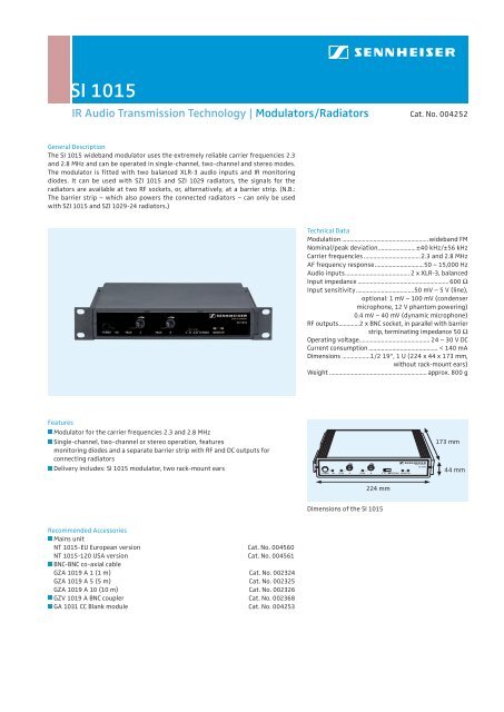
<strong>SI</strong> <strong>1015</strong><br />
IR Audio Transmission Technology | Modulators/Radiators<br />
Cat. No. 004252<br />
General Description<br />
The <strong>SI</strong> <strong>1015</strong> wideband modulator uses the extremely reliable carrier frequencies 2.3<br />
and 2.8 MHz and can be operated in single-channel, two-channel and stereo modes.<br />
The modulator is fitted with two balanced XLR-3 audio inputs and IR monitoring<br />
diodes. It can be used with SZI <strong>1015</strong> and SZI 1029 radiators, the signals for the<br />
ra diators are available at two RF sockets, or, alternatively, at a barrier strip. (N.B.:<br />
The barrier strip – which also powers the connected radiators – can only be used<br />
with SZI <strong>1015</strong> and SZI 1029-24 radiators.)<br />
Technical Data<br />
Modulation .......................................................wideband FM<br />
Nominal/peak deviation........................±40 kHz/±56 kHz<br />
Carrier frequencies ....................................2.3 and 2.8 MHz<br />
AF frequency response...............................50 – 15,000 Hz<br />
Audio inputs......................................... 2 x XLR-3, balanced<br />
Input impedance .......................................................... 600 Ω<br />
Input sensitivity.....................................50 mV – 5 V (line),<br />
optional: 1 mV – 100 mV (condenser<br />
microphone, 12 V phantom powering)<br />
0.4 mV – 40 mV (dynamic microphone)<br />
RF outputs.............2 x BNC socket, in parallel with barrier<br />
strip, terminating impedance 50 Ω<br />
Operating voltage............................................. 24 – 30 V DC<br />
Current consumption ............................................ < 140 mA<br />
Dimensions ..................1/2 19“, 1 U (224 x 44 x 173 mm,<br />
without rack-mount ears)<br />
Weight .............................................................. approx. 800 g<br />
Features<br />
Modulator for the carrier frequencies 2.3 and 2.8 MHz<br />
j<br />
Single-channel, two-channel or stereo operation, features<br />
j<br />
monitoring diodes and a separate barrier strip with RF and DC outputs for<br />
connecting radiators<br />
Delivery includes: <strong>SI</strong> <strong>1015</strong> modulator, two rack-mount ears<br />
j<br />
173 mm<br />
44 mm<br />
224 mm<br />
Dimensions of the <strong>SI</strong> <strong>1015</strong><br />
j<br />
j<br />
j<br />
j<br />
Recommended Accessories<br />
Mains unit<br />
NT <strong>1015</strong>-EU European version Cat. No. 004560<br />
NT <strong>1015</strong>-120 USA version Cat. No. 004561<br />
BNC-BNC co-axial cable<br />
GZA 1019 A 1 (1 m) Cat. No. 002324<br />
GZA 1019 A 5 (5 m) Cat. No. 002325<br />
GZA 1019 A 10 (10 m) Cat. No. 002326<br />
GZV 1019 A BNC coupler Cat. No. 002368<br />
GA 1031 CC Blank module Cat. No. 004253
<strong>SI</strong> <strong>1015</strong><br />
IR Audio Transmission Technology | Modulators/Radiators<br />
The <strong>SI</strong> <strong>1015</strong> wideband modulator can be switched between operation on one channel,<br />
operation on two channels and stereo operation. It uses the carrier frequencies<br />
2.3 and 2.8 MHz which ensure excellent transmission reliability. Together with a<br />
GA 1031 CC blank module, the compact <strong>SI</strong> <strong>1015</strong> can easily be mounted into a 19“ rack.<br />
The modulator’s controls are shown in the drawing on the left: On the very left<br />
of the front panel is the on/off switch, and the LED next to it shows whether a DC<br />
voltage is present.<br />
1 2 3 4 5 6 7 8<br />
1 On/off switch<br />
2 Mains indicator<br />
3 Peak LED for channel A<br />
4 Level control for<br />
channel A<br />
5 Peak LED for channel B<br />
Front panel of the <strong>SI</strong> <strong>1015</strong><br />
6 Level control for<br />
channel B<br />
7 Channel selector<br />
switch<br />
8 IR monitoring diodes<br />
9 10 11 12 13 14 15 16 17 18<br />
9 RF output 1 (BNC)<br />
10 RF terminal 1<br />
11 DC output terminal 1<br />
12 DC output terminal 2<br />
13 RF terminal 2<br />
14 RF output 2 (BNC)<br />
Back panel of the <strong>SI</strong> <strong>1015</strong><br />
15 Audio input B (XLR-3)<br />
15 Cable grip<br />
17 Audio input A (XLR-3)<br />
18 DC input socket<br />
(for NT <strong>1015</strong>)<br />
Mounting the <strong>SI</strong> <strong>1015</strong> into a rack: the modulator is<br />
combined with a GA 1031 CC blank module to form<br />
a 19“ unit (left), the cable grip prevents the power<br />
cable from being pulled off (right).<br />
The AF levels of channels A and B can be adjusted with controls 4 and 6. The AF<br />
level should be adjusted in such a way that the peak LEDs occasionally light up at<br />
peak volumes. With the channel selector switch (7), the modulator can be switched<br />
between mono operation on channels A or B, two-channel dual mono (A/B) and stereo<br />
operation. In stereo operation the control amplifiers of the channels are coupled.<br />
The transmitted IR signal can be checked on the modulator, as the <strong>SI</strong> <strong>1015</strong> features<br />
two monitoring diodes (8). Please remember to use a receiver which operates on the<br />
carrier frequencies 2.3 and 2.8 MHz.<br />
The back panel of the modulator features the DC input socket (see diagram on the<br />
left) where the modulator is connected to the mains via the NT <strong>1015</strong> mains unit.<br />
There is a cable grip for the power cable which should be used when rack-mounting<br />
the modulator as it prevents the connector from falling off or being pushed out<br />
of the socket. The audio signals are fed to the modulator via two electronically<br />
balanced XLR-3 input sockets (15 and 17, for channel B and A). The input sockets<br />
have line sensitivity but can optionally be fitted with microphone sensitivity<br />
for dynamic and condenser microphones (12 V phantom powering possible). The<br />
RF signal is available at two BNC sockets (9 and 14) to which you can connect<br />
SZI <strong>1015</strong>, SZI 1029, SZI 1029-10 or SZI 1029-24 radiators.<br />
Alternatively, the RF signal is available at the barrier strip: terminals 10 and 13 are<br />
in parallel with the two BNC sockets. For connection, part of the sheath of a co-axial<br />
cable must be removed, then about 1 cm of the neutral conductor must be stripped.<br />
The copper braiding is then twisted and inserted into the frame earth terminal and<br />
the neutral conductor into the terminal next to it (see drawing). When connecting<br />
the last radiator of your RF chain, do not forget to use a 50 Ω terminating impedance.<br />
The modulator’s DC supply voltage is also present at terminals 11 and 12. The <strong>SI</strong> <strong>1015</strong><br />
can thus power up to two SZI <strong>1015</strong> radiators or a single SZI 1029-24 radiator via<br />
a two-core cable. You can also use co-axial cables with additional conductors for<br />
direct current, e.g. a CVS 50-275 cable from Cordial. Your local <strong>Sennheiser</strong> dealer will<br />
be delighted to supply you with more information on this easy installation method.<br />
In general, the <strong>SI</strong> <strong>1015</strong> modulator can be used with the SZI <strong>1015</strong> radiator, all SZI 1029<br />
variants, and the SZI 30 radiator. The earlier SZI 20 radiator cannot be used, as it<br />
cannot work with the frequencies 2.3 and 2.8 MHz. Other older radiator models such<br />
as the SZI 1219 A and SZI 1019 A series models are also not suitable.<br />
Connecting a radiator to the barrier strip of the<br />
<strong>SI</strong> <strong>1015</strong>: Press down a lug with a screwdriver to<br />
open the corresponding terminal