Lagrangian Modeling of Switch Regulated DC-to-DC Power ...
Lagrangian Modeling of Switch Regulated DC-to-DC Power ...
Lagrangian Modeling of Switch Regulated DC-to-DC Power ...
Create successful ePaper yourself
Turn your PDF publications into a flip-book with our unique Google optimized e-Paper software.
1<br />
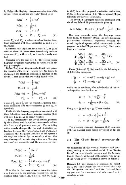
by Dl(gc) the Rayleigh dissipation c<strong>of</strong>unction <strong>of</strong> the<br />
circuit. These quantities are readily found <strong>to</strong> be<br />
z(iL) = *W2<br />
V1(9C) = +9:<br />
Dl(gc) = ;R(9C)2<br />
F;L = E ; F&=O (3.2)<br />
where F~~ and F~C are the generalized forcing functions<br />
associated with the coordinates qL and qc, respect<br />
ively,<br />
Evidently, the Lagrange equations (2.1), or (2.3),<br />
used on these EL parameters immediately rederive<br />
equation (3.1), with u = 1, as it can be esasily verified.<br />
Consider now the case u = O. The corresponding<br />
Lagrange dynamics formulation is carried out in the<br />
next paragraphs.<br />
Define To(4L) and V. (qc) as the kinetic and potential<br />
energies <strong>of</strong> the circuit, respectively. We denote by<br />
Do(4L, iC ) the Rayleigh dissipation function <strong>of</strong> the<br />
circuit. These quantities are readily found <strong>to</strong> be,<br />
70(jL) = ~L (9L)2<br />
VO(9C) = &q:<br />
Do(9L,9C) = ;R(9L – gc)z<br />
F;. = E ; F:C=O<br />
(3.3)<br />
where, F:, and @C are the generalized forcing functions<br />
ass;;iated w;th the coordinates qL and qc, respect<br />
ively.<br />
Evidently, the Lagrange equations associated with<br />
these definitions immediately rederive equation (3.1),<br />
with u = O, as it can be esasily verified.<br />
The EL parameters <strong>of</strong> the two situations generated<br />
by the different switch position values result in identical<br />
kinetic and potential energies. The switching<br />
action merely changes the Rayleigh dissipation c<strong>of</strong>unction<br />
between the values ‘Do(4c) and VI (4L, 4c).<br />
Therefore, the dissipation structure <strong>of</strong> the system is<br />
the only one affected by the switch position. One<br />
may then regard the switching action as a “damping<br />
injection”, performed through the induc<strong>to</strong>r current.<br />
in (3.3) from the proposed dissipation c<strong>of</strong>unction,<br />
DU(9L, gc), <strong>of</strong> equation (3.4). The proposed EL parameters<br />
are therefore consistent.<br />
The switched Iagrangian function associated with<br />
the above defined EL parameters is given by<br />
One then proceeds, using the Lagrange equations<br />
(2. 1), <strong>to</strong> formally obtain the switch-position<br />
parametrized differential equations defining the<br />
switch regulated system which corresponds <strong>to</strong> the<br />
proposed switched EL parameters (3.4). Such equations<br />
are given by<br />
(–)<br />
d dLu d,Cu 8D.<br />
—— = –= + Yqc (3.6)<br />
z aqc aqc<br />
Use <strong>of</strong> (3.6) on (3.5),(3.4)<br />
<strong>of</strong> differential equations<br />
result in the following set<br />
LgL = -(1 - u)~[(l – ?.6)~L- g~] +E<br />
qc<br />
c<br />
= ~[(1– U)9L– gc] (3.7)<br />
which can be rewritten, after substitution <strong>of</strong> the second<br />
equation in<strong>to</strong> the first, as<br />
qL = -(1- u)fi+:<br />
1<br />
9C = ‘~qC + (1 ‘u)tiL (3.8)<br />
Using xl = 4L and X2 = qC/C<br />
one obtains<br />
xl = –(1 –u) *Z2 + $<br />
X2 = (1 -u) :% – +32 (3.9)<br />
The proposed switched dynamics (3.9) coincides<br />
with the classical state model developed in [1] and<br />
[2].<br />
3.2 The “Buck-Boost” converter circuit<br />
7u(!iL) = ~L(tiL)2<br />
V.(qc) = *9:<br />
D.(gL, gc) = +[(1 – ~)~L– 4C]2<br />
We summarize all the relevant formulae, and equations,<br />
leading <strong>to</strong> the switched model <strong>of</strong> the “Buck-<br />
Boost” converter circuit, through and EL formulation,<br />
in Table 1, at the end <strong>of</strong> the article. The circuit<br />
<strong>of</strong> the “Buck-Boost” converter is shown in Figure 2<br />
Remark 3.1 The lagrangian approach <strong>to</strong> naodeling<br />
<strong>of</strong> the “Buck-Boost” converter reveals that only<br />
F;L = E ; F:C=O (3.4)<br />
Note that in the cases where u takes the values the “dissipation strucutre” and the ‘external forcing<br />
functions” are non-invariant with respect <strong>to</strong> the<br />
u = 1 and u = O, one recovers, respectively, the dissipation<br />
c<strong>of</strong>unctions DI (it) in (3.2) and Do(4L, 9C ) switching action.<br />
4494


