Contribution of Multidimensional Trellis Coding in VDSL Systems
Contribution of Multidimensional Trellis Coding in VDSL Systems
Contribution of Multidimensional Trellis Coding in VDSL Systems

Create successful ePaper yourself
Turn your PDF publications into a flip-book with our unique Google optimized e-Paper software.
SETIT 2005<br />
3 rd International Conference: Sciences <strong>of</strong> Electronic,<br />
Technologies <strong>of</strong> Information and Telecommunications<br />
March 27-31, 2005 – TUNISIA<br />
<strong>Contribution</strong> <strong>of</strong> <strong>Multidimensional</strong> <strong>Trellis</strong> <strong>Cod<strong>in</strong>g</strong> <strong>in</strong><br />
<strong>VDSL</strong> <strong>Systems</strong><br />
Mohamed Tlich, Meryem Ouzzif, and Ahmed Zeddam<br />
France Télécom Division R&D RESA<br />
2, Avenue Pierre Marz<strong>in</strong>-22307 Lannion Cedex<br />
mohamed.tlich@rd.francetelecom.com<br />
meryem.ouzzif@francetelecom.com<br />
ahmed.zeddam@francetelecom.com<br />
Abstract: In this paper, we take a new look at the s<strong>in</strong>gle-carrier modulation technique for <strong>VDSL</strong> system. Us<strong>in</strong>g<br />
powerful cod<strong>in</strong>g techniques can further <strong>in</strong>crease the performance <strong>of</strong> a Quadrature Amplitude Modulation (QAM)<br />
system. This paper <strong>in</strong>vestigates an implementation <strong>of</strong> the trellis cod<strong>in</strong>g <strong>in</strong> a s<strong>in</strong>gle-carrier modulation (SCM) <strong>VDSL</strong><br />
system <strong>in</strong>tended for transmissions over short copper cables. The suggested code is a 4-dimensional 16-state trellis<br />
coder; it ga<strong>in</strong>s typically 4dB over uncoded transmissions <strong>in</strong> an AWGN environment. For suitable values <strong>of</strong> the<br />
truncation length <strong>of</strong> the Viterbi decoder, the results <strong>of</strong> the simulations carried out showed that the trellis cod<strong>in</strong>g<br />
implemented over the SCM-<strong>VDSL</strong> system, <strong>in</strong>troduces an important ga<strong>in</strong> <strong>in</strong> either the range <strong>of</strong> the twisted copper-pair,<br />
or <strong>in</strong> channel capacity.<br />
Key words: twisted copper pair cable, xDSL, Quadrature Amplitude Modulation (QAM), <strong>Trellis</strong> Coded Modulation<br />
(TCM), Crosstalk.<br />
1 <strong>VDSL</strong> Overview<br />
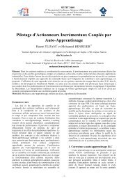
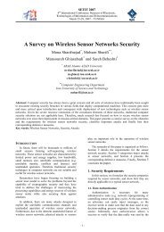
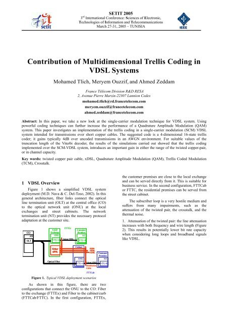
Figure 1 shows a simplified <strong>VDSL</strong> system<br />
deployment (M.D. Nava & C. Del-Toso, 2002). In this<br />
general architecture, fiber l<strong>in</strong>ks connect the optical<br />
l<strong>in</strong>e term<strong>in</strong>ation unit (OLT) at the central <strong>of</strong>fice (CO)<br />
to the optical network unit (ONU) at the local<br />
exchanges and street cab<strong>in</strong>ets. The network<br />
term<strong>in</strong>ation unit (NT) provides the necessary protocol<br />
adaptation at the customer site.<br />
CO<br />
AN<br />
OLT<br />
Local<br />
Exchange<br />
ONU<br />
VTU-O<br />
FTTEx<br />
Liaison <strong>VDSL</strong><br />
Customer<br />
Premises<br />
NT<br />
VTU-R<br />
the customer premises are close to the local exchange<br />
and can be served directly from it. This is suitable for<br />
bus<strong>in</strong>ess service. In the second configuration, FTTCab<br />
or FTTC, the residential premises can be served from<br />
the street cab<strong>in</strong>et.<br />
The subscriber loop is a very hostile medium and<br />
suffers from many impairments, such as the<br />
attenuation <strong>of</strong> the twisted pair, the crosstalk, and the<br />
thermal noise.<br />
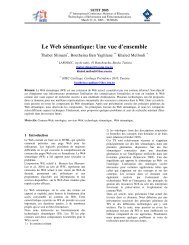
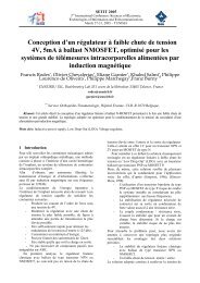
1. Attenuation <strong>of</strong> the twisted pair: the l<strong>in</strong>e attenuation<br />
<strong>in</strong>creases with both frequency and wire length (Figure<br />
2). This results <strong>in</strong> potentially lower bit rate capacity<br />
when consider<strong>in</strong>g long loops and broadband signals<br />
like <strong>VDSL</strong>.<br />
Other<br />
xDSL<br />
Optical Fiber<br />
Cab<strong>in</strong>et<br />
ISDN<br />
HDSL<br />
ADSL<br />
Customer<br />
Premises<br />
ONU<br />
VTU-O<br />
Liaison <strong>VDSL</strong><br />
NT<br />
VTU-R<br />
Distribution<br />
Cable<br />
FTTCab<br />
Figure 1. Typical <strong>VDSL</strong> deployment scenarios<br />
As shown <strong>in</strong> this figure, there are two<br />
configurations that connect the ONU to the CO: Fiber<br />
to the exchange (FTTEx) and Fiber to the cab<strong>in</strong>et/curb<br />
(FTTCab/FTTC). In the first configuration, FTTEx,
SETIT2005<br />
20Log10(|H(f)|<br />
0<br />
−10<br />
−20<br />
−30<br />
−40<br />
−50<br />
−60<br />
−70<br />
1300m<br />
Channel Attenuation<br />
500m<br />
1000m<br />
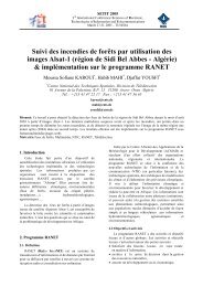
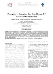
270-1 v2.0.6 part1, 2002), we will deal with the<br />
32QAM constellation shown <strong>in</strong> Figure 4 we used <strong>in</strong><br />
our simulations. This constellation is <strong>in</strong>variant to 90°<br />
rotations. Therefore, to make the system transparent to<br />
90° phase <strong>of</strong>fsets, when mapp<strong>in</strong>g bits <strong>in</strong>to<br />
constellation po<strong>in</strong>ts:<br />
1. 3 bits (Q3n, Q4n and Q5n) are assigned to po<strong>in</strong>ts<br />
with<strong>in</strong> a quadrant so that a 90° rotation leaves them<br />
unchanged, as shown <strong>in</strong> the constellation <strong>of</strong> Figure 4.<br />
2. The two first bits (Q1n and Q2n) are differentially<br />
encoded to specify the quadrant, i.e., bits Q1n and<br />
Q2n will determ<strong>in</strong>e the change <strong>in</strong> quadrant from<br />
symbol to symbol us<strong>in</strong>g the rules listed <strong>in</strong> table 1.<br />
−80<br />
0 0.5 1 1.5 2 2.5<br />
Freq (Hz)<br />
3 3.5 4 4.5<br />
x 10 6<br />
xx111<br />
xx011<br />
xx110<br />
xx010<br />
Figure 2. Signal attenuation for a 500m, 1000m and 1300m<br />
wire length<br />
2. Crosstalk: is noise caused by electromagnetic<br />
radiation <strong>of</strong> other telephone l<strong>in</strong>es physically located <strong>in</strong><br />
close proximity <strong>in</strong> the same cable b<strong>in</strong>der. Such<br />
coupl<strong>in</strong>g <strong>in</strong>creases with frequency, so it is very<br />
harmful for <strong>VDSL</strong>, which uses bandwidth up to 12<br />
MHz. Practically, we can dist<strong>in</strong>guish two types <strong>of</strong><br />
crosstalk: Near-End crosstalk (NEXT) caused by<br />
signals travel<strong>in</strong>g <strong>in</strong> opposite directions <strong>in</strong> the same<br />
cable b<strong>in</strong>der, and Far-End crosstalk (FEXT) caused by<br />
signals travel<strong>in</strong>g <strong>in</strong> the same direction as shown <strong>in</strong><br />
Figure 3.<br />
L<strong>in</strong>e 1<br />
L<strong>in</strong>e i<br />
NEXT<br />
L<strong>in</strong>e 1<br />
L<strong>in</strong>e i<br />
Figure 3. NEXT and FEXT <strong>in</strong> cable b<strong>in</strong>der<br />
FEXT<br />
3. Thermal or background noise: a convention <strong>in</strong><br />
standardization committees is to model background<br />
noise as additive white Gaussian noise (AWGN) with<br />
a fixed Power Spectral Density (PSD) level equal to -<br />
140 dBm/Hz as def<strong>in</strong>ed <strong>in</strong> (ETSI TS 101 270-1 v2.0.6<br />
part1, 2002)(ETSI TS 101 270-2 v2.0.3 part2, 2002).<br />
qi<br />
Serial to<br />
Parallel<br />
Converter<br />
xx010<br />
xx110<br />
xx011<br />
xx101<br />
xx100<br />
xx001<br />
xx111 xx101 xx100<br />
Q5n<br />
Q4n<br />
Q3n<br />
Q2n<br />
Q1n<br />
xx010<br />
xx001<br />
xx100<br />
xx101<br />
xx111<br />
xx000 xx000 xx001 xx011<br />
xx000 xx000 xx100 xx110<br />
xx110<br />
xx001 xx101 xx010<br />
xx011<br />
Table 2.1<br />
xx111<br />
Y2n−1<br />
D<br />
Y1n−1<br />
D<br />
Differential Encoder<br />
Figure 4. Symbol Mapper<br />
Y5n<br />
Y4n<br />
Y3n<br />
Y2n<br />
Y1n<br />
Complex<br />
Symbol<br />
Mapper<br />
Inputs Previous Outputs Current Outputs<br />
Q1n Q2n Y1n-1 Y2n-1 Y1n Y2n<br />
1 0 0 0 0 1<br />
1 0 0 1 1 0<br />
Cn<br />
2 <strong>Trellis</strong> <strong>Cod<strong>in</strong>g</strong> <strong>in</strong> AWGN Passband<br />
Channels<br />
<strong>Trellis</strong> Coded Modulation us<strong>in</strong>g four-dimensional<br />
constellations have a better performance <strong>in</strong> terms <strong>of</strong><br />
complexity and cod<strong>in</strong>g ga<strong>in</strong> over the usual twodimensional<br />
schemes (Lee-Fang Wei, 1987).<br />
Actual SCM-<strong>VDSL</strong> systems use the twodimensional<br />
Differential Quadrature Amplitude<br />
Modulation (DQAM) scheme (ETSI TS 101 270-1<br />
v2.0.6 part1, 2002). In this section, we demonstrate<br />
that us<strong>in</strong>g the 4-dimensional <strong>Trellis</strong> Coded Modulation<br />
as a function <strong>of</strong> the truncation length <strong>of</strong> the Viterbi<br />
decoder can further <strong>in</strong>crease the performance <strong>of</strong> this<br />
DQAM system, from a cod<strong>in</strong>g ga<strong>in</strong> and cable range<br />
viewpo<strong>in</strong>ts.<br />
2.1 DQAM Pr<strong>in</strong>cipe<br />
To fully understand the DQAM (ETSI TS 101<br />
1 0 1 0 1 1<br />
1 0 1 1 0 0<br />
Table 1. Differential QAM <strong>Cod<strong>in</strong>g</strong> table<br />
2.2 <strong>Trellis</strong> Coded Modulation: A modified WEI 16-<br />
State 4D Code<br />
An <strong>in</strong>herent cost <strong>of</strong> the coded schemes is that the<br />
size <strong>of</strong> the 2D constellation is doubled over uncoded<br />
schemes. This is due to the fact that a redundant bit is<br />
added every signal<strong>in</strong>g <strong>in</strong>terval. Otherwise, the cod<strong>in</strong>g<br />
ga<strong>in</strong> <strong>of</strong> those coded schemes would be 3 dB greater.<br />
Us<strong>in</strong>g multidimensional (>2) constellations with a<br />
trellis code <strong>of</strong> rate m/m+1 (Lee-Fang Wei, 1987) can<br />
reduce that cost because fewer redundant bits are<br />
added for each 2D signal<strong>in</strong>g <strong>in</strong>terval. Furthermore,<br />
multidimensional encod<strong>in</strong>g provides more flexibility<br />
than 2D encod<strong>in</strong>g <strong>in</strong> that it can use a fractional<br />
number <strong>of</strong> bits per symbol.
SETIT2005<br />
We will focus, now, on the case where the number<br />
Q <strong>of</strong> <strong>in</strong>formation bits transmitted per signal<strong>in</strong>g <strong>in</strong>terval<br />
is equal to 5. These five <strong>in</strong>formation bits arriv<strong>in</strong>g <strong>in</strong><br />
the current signal<strong>in</strong>g <strong>in</strong>terval n are denoted as I1n,<br />
I2n… and I5n.<br />
A 2/3 rate, 16-state code with a 4D rectangular<br />
constellation <strong>of</strong> 211 po<strong>in</strong>ts and a M<strong>in</strong>imum Square<br />
Euclidean Distance (MSED) d 2 0 is shown <strong>in</strong> Figure 5.<br />
The 4D constellation is constructed from a 48-po<strong>in</strong>t<br />
2D constellation partitioned <strong>in</strong>to eight subsets with<br />
enlarged MSED equal to 4d 2 0 , as expla<strong>in</strong>ed <strong>in</strong> (Lee-<br />
Fang Wei, 1987).<br />
I5_n+1<br />
I4_n+1<br />
I3_n+1<br />
I2_n+1<br />
I1_n+1<br />
I5_n<br />
I4_n<br />
I3_n<br />
I2_n<br />
I1_n<br />
DIFFERENTIAL<br />
ENCODING<br />
I3_n’<br />
I2_n’<br />
W2n<br />
2T<br />
W3n<br />
2T<br />
<strong>Trellis</strong> ENCODER<br />
W1n<br />
2T<br />
W4n<br />
2T<br />
I3_n’<br />
I2_n’<br />
I1_n<br />
Y0_n<br />
BIT<br />
CONVERTOR<br />
T<br />
2 T<br />
Z10_n<br />
Z9_n<br />
Z8_n<br />
Z7_n<br />
Z6_n<br />
Z5_n<br />
Z4_n<br />
Z1_n+1<br />
Z0_n+1<br />
Z1_n<br />
Z0_n<br />
Exlusive OR<br />
Signal<strong>in</strong>g Interval<br />
Delay Element<br />
Figure 5. 16-State code with 4D Rectangular constellation<br />
If we denote the current and next states <strong>of</strong> the<br />
trellis encoder as W1pW2pW3pW4p, p=n and n+2, the<br />
correspond<strong>in</strong>g 16-state trellis diagram is shown <strong>in</strong><br />
Figure 6.<br />
CURRENT<br />
NEXT<br />
STATE STATE<br />
10log<br />
2<br />
⎛ 4d0<br />
⎜<br />
⎜ 31.33d<br />
⎜ 2<br />
d0<br />
⎜<br />
2<br />
⎝ 20d0<br />
⎞<br />
⎟<br />
2<br />
0 ⎟<br />
10<br />
=<br />
⎟<br />
⎟<br />
⎠<br />
4.0713<br />
dB<br />
Where 31.33 d 2<br />
0 is the average power <strong>of</strong> the 4D<br />
constellation, and 20d 2 0 is the average power <strong>of</strong> the<br />
32QAM.<br />
2.3 Simulation Results<br />
Bit Error Rates (BER) for the two different<br />
systems have been simulated, the uncoded system (32<br />
DQAM), and the 4D 16-state code TCM system with<br />
a Viterbi decoder us<strong>in</strong>g a truncation length equal to K.<br />
In this stage <strong>of</strong> simulation, the system is simulated<br />
only with the AWGN disturbance.<br />
The results <strong>of</strong> the BER simulations, for 105<br />
<strong>in</strong>formation bits sent, are shown <strong>in</strong> Figure 7. This<br />
figure shows the BER values for different Signal-to-<br />
Noise Ratios (SNR) and for different values <strong>of</strong> the<br />
truncation length K. Both systems have the same<br />
<strong>in</strong>formation rate (5 <strong>in</strong>formation bits/symbol period).<br />
Table 2 shows that the BER decreases with K.<br />
However, the BER values become very similar for the<br />
values <strong>of</strong> K that exceed 125.<br />
BER<br />
10 −1<br />
10 −2<br />
10 −3<br />
32QAM non codée<br />
MCT:Tronc 10<br />
MCT:Tronc 40<br />
MCT:Tronc 125<br />
MCT:Tronc 500<br />
MCT:Tronc 5000<br />
MCT:No Tronc<br />
4D SUBSET<br />
0 2 1 3<br />
4 6 5 7<br />
2 0 3 1<br />
W1n W2n W3n W4n W1n+2 W2n+2 W3n+2 W4n+2<br />
0 0 0 0<br />
0<br />
0 0 0 0<br />
2<br />
0 0 0 1<br />
3<br />
1<br />
0 0 0 1<br />
0 0 1 0<br />
0 0 1 0<br />
6 4 7 5<br />
1 3 0 2<br />
0 0 1 1<br />
0 1 0 0<br />
0 0 1 1<br />
0 1 0 0<br />
10 0 SNR (dB)<br />
10 −4<br />
10 −5<br />
0 5 10 15 20 25<br />
5 7 4 6<br />
3 1 2 0<br />
7 5 6 4<br />
2 0 3 1<br />
6 4 7 5<br />
0 1 0 1<br />
0 1 1 0<br />
0 1 1 1<br />
1 0 0 0<br />
1 0 0 1<br />
0 1 0 1<br />
0 1 1 0<br />
0 1 1 1<br />
1 0 0 0<br />
1 0 0 1<br />
Figure 7. 4D TCM performance <strong>in</strong> AWGN channel<br />
As shown <strong>in</strong> Figure 7, asymptotically, the system<br />
employ<strong>in</strong>g 4D TCM code ga<strong>in</strong>s approximately 4 dB <strong>of</strong><br />
SNR over the uncoded system.<br />
0 2 1 3<br />
1 0 1 0<br />
1 0 1 0<br />
4 6 5 7<br />
3 1 2 0<br />
7 5 6 4<br />
1 3 0 2<br />
5 7 4 6<br />
1 0 1 1<br />
1 1 0 0<br />
1 1 0 1<br />
1 1 1 0<br />
1 1 1 1<br />
1 0 1 1<br />
1 1 0 0<br />
1 1 0 1<br />
1 1 1 0<br />
1 1 1 1<br />
Figure 6. <strong>Trellis</strong> Diagram <strong>of</strong> 16-State code <strong>of</strong> Figure 5<br />
The cod<strong>in</strong>g ga<strong>in</strong> <strong>of</strong> the trellis coded modulation<br />
over the uncoded 32QAM therefore is:<br />
SNR = 18<br />
K 10 20 40 125<br />
BER 0.0171 0.0096 0.0065 0.004<br />
K 500 5000 No Trunc<br />
BER 0.0051 0.0031 0.0039<br />
SNR = 19<br />
K 10 20 40 125<br />
BER 0.0054 0.0026 0.0018 5.6e-4<br />
K 500 5000 No Trunc<br />
BER 3e-4 2e-4 2.7e-4
SETIT2005<br />
SNR = 20<br />
K 10 20 40 125<br />
BER 0.0013 3.3e-4 1.5e-4 0<br />
K 500 5000 No Trunc<br />
BER 0 0 0<br />
Table 2. Effect <strong>of</strong> truncation length on the performance <strong>of</strong><br />
the 4D TCM Code<br />
3 <strong>Trellis</strong> <strong>Cod<strong>in</strong>g</strong> <strong>in</strong> Twisted Copper-Pair<br />
Passband Channels<br />
As specified <strong>in</strong> ANSI and ETSI (ETSI TS 101<br />
270-1 v2.0.6 part1, 2002)(ETSI TS 101 270-2 v2.0.3<br />
part2, 2002) functional documents, SCM-<strong>VDSL</strong><br />
systems don’t use convolutional cod<strong>in</strong>g. In what<br />
follows, we will study the contribution <strong>of</strong> the TCM <strong>in</strong><br />
the SCM-<strong>VDSL</strong> systems. The achievable ga<strong>in</strong>s for<br />
systems us<strong>in</strong>g the scheme consist<strong>in</strong>g <strong>of</strong> 4D <strong>Trellis</strong><br />
Coded Modulation have been analyzed <strong>in</strong> the previous<br />
section, and are typically equal to 4 dB for an AWGN<br />
channel.<br />
3.1 SCM-<strong>VDSL</strong> system<br />
Figure 8 presents the SCM-<strong>VDSL</strong> system (T. Starr &<br />
M. Sorbara & J.M. Ci<strong>of</strong>fi & P.J. Silverman, 2003) we<br />
used <strong>in</strong> our simulations. For the sake <strong>of</strong> simplification,<br />
the Reed-Solomon cod<strong>in</strong>g and <strong>in</strong>terleav<strong>in</strong>g functions,<br />
whose ma<strong>in</strong> purpose is to protect the data from<br />
Impulse Noise, have not been <strong>in</strong>troduced <strong>in</strong> that<br />
system because the purpose <strong>of</strong> our study is not to<br />
<strong>in</strong>vestigate the impact <strong>of</strong> Impulse Noise on <strong>VDSL</strong><br />
transmission, but to demonstrate the advantage <strong>of</strong><br />
us<strong>in</strong>g the TCM rather than the DQAM modulation.<br />
fractionally spaced equalizer (MMSE) at a new<br />
sampl<strong>in</strong>g rate equal to 2×symbolrate because the <strong>in</strong>put<br />
is now a baseband signal. The received symbols are<br />
decoded and compared to the orig<strong>in</strong>ally transmitted<br />
data <strong>in</strong> order to compute the errors caused by the noise<br />
burst, and consequently, to compare the DQAM and<br />
TCM modulations.<br />
3.2 Impairment Generator<br />
The impairment generator produces the noise that<br />
is <strong>in</strong>jected <strong>in</strong>to the simulation set. It <strong>in</strong>cludes both<br />
crosstalk noise and background noise.<br />
The crosstalk noise power level varies with the<br />
frequency, the length <strong>of</strong> the cable loop, and the<br />
transmit direction (Upstream or Downstream). The<br />
crosstalk model (ETSI TS 101 270-2 v2.0.3 part2,<br />
2002) applied accord<strong>in</strong>g to the test scenarios we<br />
choose is described below.<br />
Figure 9 def<strong>in</strong>es a functional diagram <strong>of</strong> the<br />
composite impairment noise. This diagram has the<br />
follow<strong>in</strong>g elements:<br />
1. The three impairment "generators" G1, G2, and G3<br />
generate noise as def<strong>in</strong>ed <strong>in</strong> (T. Starr & M. Sorbara &<br />
J.M. Ci<strong>of</strong>fi & P.J. Silverman, 2003).<br />
2. The transfer function H 1 (f, d) models the length<br />
and frequency dependency <strong>of</strong> the NEXT impairment<br />
as specified <strong>in</strong> (T. Starr & M. Sorbara & J.M. Ci<strong>of</strong>fi &<br />
P.J. Silverman, 2003).<br />
3. The transfer function H 2 (f, d) models the length<br />
and frequency dependency <strong>of</strong> the FEXT impairment as<br />
specified <strong>in</strong> (T. Starr & M. Sorbara & J.M. Ci<strong>of</strong>fi &<br />
P.J. Silverman, 2003).<br />
NEXT noise<br />
Independent noise<br />
Generators<br />
G1<br />
Crosstalk transfer<br />
functions<br />
H1(f,d)<br />
S1<br />
FEXT noise<br />
G2<br />
H2(f,d)<br />
S2<br />
FSAN SUM<br />
Background noise<br />
Cable <strong>in</strong>dependent<br />
G3<br />
S3<br />
Figure 9. Functional diagram <strong>of</strong> the impairment noise<br />
composition<br />
Figure 8. <strong>VDSL</strong> Transmission Cha<strong>in</strong><br />
To satisfy the sampl<strong>in</strong>g theorem, the QAM<br />
symbols x k are over-sampled at the sampl<strong>in</strong>g rate<br />
4×symbolrate, and are shaped us<strong>in</strong>g a raised cos<strong>in</strong>e<br />
filter ϕ<br />
p<br />
(t)<br />
before be<strong>in</strong>g sent through the channel.<br />
Inter-Symbol Interference (ISI), Additive White<br />
Gaussian Noise (AWGN), and crosstalk impair s<strong>in</strong>glecarrier<br />
transmission over the copper pairs. After be<strong>in</strong>g<br />
modulated and sent through the channel, an Additive<br />
White Gaussian and crosstalk Noises are<br />
superimposed to the channel output <strong>in</strong> the time<br />
doma<strong>in</strong>. After cross<strong>in</strong>g the whiten<strong>in</strong>g filter g(t), the<br />
data, brought back to the baseband, are sent through a<br />
low-pass filter <strong>in</strong> order to elim<strong>in</strong>ate the whitened noise<br />
situated out <strong>of</strong> the frequency band. After that, they are<br />
sent through a f<strong>in</strong>ite m<strong>in</strong>imum-mean-square-error<br />
Several deployment scenarios have been identified<br />
to achieve <strong>VDSL</strong> simulations. Each scenario (noise<br />
model) results <strong>in</strong> a length dependant PSD description<br />
<strong>of</strong> noise. Some <strong>of</strong> the three <strong>in</strong>dividual impairment<br />
generators G1, G2, and G3, are used more once <strong>in</strong> the<br />
same noise model.<br />
We denote six models, Type "A", Type "B", and<br />
Type "C" for cab<strong>in</strong>et model<strong>in</strong>g and Type "D", Type<br />
"E", and Type "F" for exchange model<strong>in</strong>g (ETSI TS<br />
101 270-2 v2.0.3 part2, 2002). In our simulations, we<br />
chose Type "A" as the impairment model<strong>in</strong>g.<br />
Type "A" models (Cab<strong>in</strong>et) are <strong>in</strong>tended to<br />
represent a mixed scenario <strong>in</strong>clud<strong>in</strong>g full ADSL where<br />
the <strong>VDSL</strong> system is placed <strong>in</strong> a distribution cable (up<br />
to ten <strong>of</strong> wire pairs) that is filled with many other<br />
transmission systems: 10 ADSL, 4 HDSL, and 20<br />
ISDN <strong>in</strong>terferers.
SETIT2005<br />
3.3 Simulation Results<br />
The <strong>VDSL</strong> system shall operate with a bit error<br />
ratio < 1 erroneous bit through 10 7 bits sent when<br />
operated over any loop with the noise models and<br />
simulation conditions specified <strong>in</strong> this section.<br />
Because <strong>of</strong> computer restrictions, we carried our<br />
simulations with a BER level equal to 10 -5 .<br />
Simulation defaults: We have simulated the 4D<br />
TCM method <strong>in</strong> the <strong>VDSL</strong> system described <strong>in</strong> Figure<br />
8 with three configurations <strong>of</strong> the truncation length K<br />
<strong>of</strong> the Viterbi decoder: K = 10, K = 125, and without<br />
truncation.<br />
The set <strong>of</strong> default parameters used <strong>in</strong> the<br />
simulations is listed below:<br />
• Number <strong>of</strong> Feed-Forward Equalizer (FFE)<br />
taps=32.<br />
• Roll-<strong>of</strong>f factor: α = 0. 2 .<br />
• Number <strong>of</strong> <strong>in</strong>formation bits per signal<strong>in</strong>g<br />
<strong>in</strong>terval=5.<br />
• Symbol rate: f baud = 2.16 MHz.<br />
• Carrier frequency: f c = 2.2275 MHz.<br />
• Sampl<strong>in</strong>g rate: f s = 4f baud = 8.64 MHz.<br />
• The sampl<strong>in</strong>g rate at the <strong>in</strong>put <strong>of</strong> the MMSE-FSE<br />
equalizer is L x f baud with L = 2.<br />
• Transmitted constellations = 32QAM for noncoded<br />
transmission, and 48QAM for trellis coded<br />
transmission.<br />
• The noise is additive, colored, and Gaussian<br />
ACGN. When whitened, its power spectral density<br />
(PSD) level is fixed to typically -140 dBm/Hz, which<br />
usually corresponds to the reference noise floor <strong>in</strong> the<br />
<strong>VDSL</strong> system.<br />
• As specified <strong>in</strong> the functional requirement<br />
documents (ETSI TS 101 270-1 v2.0.6 part1,<br />
2002)(ETSI TS 101 270-2 v2.0.3 part2, 2002), the<br />
PSD <strong>of</strong> the transmitted modulated signal is typically<br />
equal to -60 dBm/Hz.<br />
Simulation results: In tables 3 and 4, we show the<br />
cable range reaches and the channel capacity ga<strong>in</strong>s for<br />
the 4D TCM <strong>VDSL</strong> system.<br />
On one hand, Table 3 shows the difference <strong>in</strong> cable<br />
range reaches if we vary the truncation length K. For<br />
the values <strong>of</strong> K that exceed 125, the 4D TCM <strong>VDSL</strong><br />
cable range is typically constant. It is approximatively<br />
equal to 1270 m.<br />
On the other hand, the reach <strong>in</strong> the case <strong>of</strong> the<br />
32QAM non-coded <strong>VDSL</strong> system is typically equal to<br />
1180 m. In fact, the channel capacity associated for<br />
this value <strong>of</strong> the cable range is equal to 4.9823 bits.<br />
Beyond this value, the channel capacity becomes<br />
lower than the number <strong>of</strong> bits we want to send each<br />
signal<strong>in</strong>g <strong>in</strong>terval (b = 5). Thus, the 4D TCM <strong>VDSL</strong><br />
system gives a cable range ga<strong>in</strong> <strong>of</strong> 90m with the<br />
suitable value <strong>of</strong> K = 125.<br />
Table 4 shows the channel capacity ga<strong>in</strong> <strong>in</strong> terms<br />
<strong>of</strong> number <strong>of</strong> bits we can send through the channel for<br />
different values <strong>of</strong> cable ranges and K. We note that<br />
the use <strong>of</strong> the trellis Coded Modulation rather than the<br />
DQAM allows send<strong>in</strong>g 5 bits/signal<strong>in</strong>g <strong>in</strong>terval, even<br />
when the channel capacity (denoted bpsi <strong>in</strong> Table 4),<br />
calculated without tak<strong>in</strong>g <strong>in</strong>to account the ga<strong>in</strong><br />
<strong>in</strong>troduced by the TCM, is lower than 5. In our<br />
simulations, for K = 125 and BER = 10 -5 , the ga<strong>in</strong><br />
<strong>in</strong>troduced by the TCM <strong>in</strong>creases the channel capacity<br />
by 0.957 bits per signal<strong>in</strong>g <strong>in</strong>terval, which corresponds<br />
to 0.957 × 2.16 = 2.067 Mbps <strong>of</strong> rate ga<strong>in</strong>.<br />
Cable Length Erroneous Symbols BER<br />
K = 10<br />
1210 0 0<br />
1220 0 0<br />
1230 2 0.6e-5<br />
1240 6 e-5<br />
1250 6 1.2e-5<br />
1260 27 5.3e-5<br />
K = 125<br />
1260 0 0<br />
1270 0 0<br />
1280 5 1.2e-5<br />
1290 36 7e-5<br />
1300 39 9.7e-5<br />
Without Truncation<br />
1270 0 0<br />
1290 0 0<br />
1300 20 4.3e-5<br />
1400 247 5.22e-4<br />
Table 3. TCM SCM-<strong>VDSL</strong>: Cable range reaches for<br />
different values <strong>of</strong> the truncation length K<br />
K<br />
Cable<br />
Length<br />
Bpsi<br />
Ga<strong>in</strong><br />
10 1230 4.5822 0.4178<br />
125 1270 4.043 0.957<br />
No Trunc 1290 3.8172 1.1828<br />
Table 4. Channel capacity ga<strong>in</strong> for different values <strong>of</strong> K<br />
Conclusion<br />
The <strong>VDSL</strong> system is expected to be the solution to<br />
provide broadband services to residential and bus<strong>in</strong>ess<br />
on the exist<strong>in</strong>g copper plant.<br />
In this paper, we demonstrated that the <strong>Trellis</strong>-<br />
Coded Modulation with 4-dimensional rectangular<br />
constellations is superior to us<strong>in</strong>g 2D constellations.<br />
Us<strong>in</strong>g multi-dimensional rectangular constellations<br />
not only reduces the size <strong>of</strong> the constituent 2D<br />
constellations, but also improves the performance <strong>in</strong><br />
terms <strong>of</strong> both the cod<strong>in</strong>g ga<strong>in</strong> and cable range reaches.
SETIT2005<br />
The simulation model was based on the s<strong>in</strong>glecarrier<br />
modulation technique Quadrature Amplitude<br />
Modulation (QAM). 4-Dimensional 16-state trellis<br />
code with Viterbi decod<strong>in</strong>g truncation length K was<br />
has been suggested as a suitable cod<strong>in</strong>g scheme with a<br />
value <strong>of</strong> K = 125. It has been evaluated <strong>in</strong> both<br />
AWGN and twisted copper-pair channels and has<br />
shown a cod<strong>in</strong>g ga<strong>in</strong> <strong>of</strong> approximatively 4dB <strong>in</strong> the<br />
AWGN channel. It has, also, shown a cable range ga<strong>in</strong><br />
<strong>of</strong> approximatively 90m, and a channel capacity ga<strong>in</strong><br />
<strong>of</strong> typically 0.95 bits/signal<strong>in</strong>g <strong>in</strong>terval for K = 125<br />
and a BER level <strong>of</strong> 10-5, which corresponds to a rate<br />
ga<strong>in</strong> <strong>of</strong> 2.067 Mbps.<br />
References<br />
ETSI TS 101 270-1 v2.0.6 (2002-11). Transmission and<br />
Multiplex<strong>in</strong>g (TM); Access transmission systems on<br />
metallic access cables; Very high speed Digital<br />
Subscriber L<strong>in</strong>e (<strong>VDSL</strong>); Part 1 : Functional<br />
requirements.<br />
ETSI TS 101 270-2 v2.0.3 (2002-10). Transmission and<br />
Multiplex<strong>in</strong>g (TM); Access transmission systems on<br />
metallic access cables; Very high speed Digital<br />
Subscriber L<strong>in</strong>e (<strong>VDSL</strong>); Part 2 : Transceiver<br />
Specification.<br />
Lee-Fang. Wei. <strong>Trellis</strong>-coded modulation with<br />
multidimensioanl constellations. IEEE Transactions on<br />
Communications Theory, IT-33(4), July 1987.<br />
Mario Diaz Nava and Christophe Del-Toso. A short<br />
overview <strong>of</strong> the vdsl system requirements. IEEE<br />
Communications Magaz<strong>in</strong>e, December 2002.<br />
T. Starr, M. Sorbara, J.M. Ci<strong>of</strong>fi, P.J. Silverman. DSL<br />
Advances, Prentice Hall Inc., New Jersey, 2003.