Archive of SID
Archive of SID
Archive of SID

Create successful ePaper yourself
Turn your PDF publications into a flip-book with our unique Google optimized e-Paper software.
S. Deepa and S. Rajapandian /IJE TRANSACTIONS C: Aspects Vol. 26, No. 3, (March 2013) 309-314 310<br />
toward connecting small power resources to the medium<br />
and low voltage network [2]. Power quality standards<br />
for connection <strong>of</strong> an inverter to the grid are still under<br />
development, since previously there have been a few<br />
similar high power applications. In [3] it is stated that<br />
the power quality is determined by the voltage quality,<br />
when the voltage is a controlled variable. In order to<br />
deliver a good ac power the controlled pulse width<br />
modulation (PWM) inverter and L-C output filter have<br />
to convert a dc voltage source (e.g. batteries) to a<br />
sinusoidal ac voltage with low voltage THD and fast<br />
transient response under load disturbances.<br />
Another important aspect <strong>of</strong> power quality is<br />
harmonic distortion. General requirements for harmonic<br />
distortion can be found in standard [4] and particularly<br />
for connection <strong>of</strong> distributed resources to grid in [4].<br />
PWM control is the most powerful technique that <strong>of</strong>fers<br />
a simple method for control <strong>of</strong> analog systems with the<br />
processor's digital output [5]. With the availability <strong>of</strong><br />
low cost high performance DSP chips characterized by<br />
the execution <strong>of</strong> most instructions in one instruction<br />
cycle, complicated control algorithms can be executed<br />
with fast speed, making very high sampling rate<br />
possible for digitally-controlled inverters [6]. The Z-<br />
source inverter, utilizing a unique LC network and<br />
previously forbidden shoot-through states, provides<br />
unique features, such as the ability to buck and boost<br />
voltage with a simple single stage structure The Z-<br />
source inverter exhibits new operation modes that have<br />
not been discussed before. This analyzes these new<br />
operation modes and the associated circuit<br />
characteristics [7]. Depending upon the boosting factor<br />
capability <strong>of</strong> impedance network the rectified DC<br />
voltage is buck or boost upto the voltage level <strong>of</strong> the<br />
inverter section (not exceed to the DC bus voltage). This<br />
network also acts as a second order filter and it should<br />
be required less number <strong>of</strong> inductor and capacitorc [8,<br />
9]. In this paper, the modeling and control <strong>of</strong> voltage<br />
sag/swell compensation using new control technique<br />
based dynamic voltage restorer are simulated using<br />
MATLAB s<strong>of</strong>tware. The simulation results are<br />
presented to show the effectiveness <strong>of</strong> the proposed<br />
control method.<br />
The DVR works independent <strong>of</strong> the type <strong>of</strong> fault or any<br />
event that happens in the system, provided that the<br />
whole system remains connected to the supply grid, i.e.<br />
the line breaker does not trip. For most practical cases, a<br />
more economical design can be achieved by only<br />
compensating the positive and negative sequence<br />
components <strong>of</strong> the voltage disturbance seen at the input<br />
<strong>of</strong> the DVR. This option is reasonable because for a<br />
typical distribution bus configuration, the zero sequence<br />
part <strong>of</strong> a disturbance will not pass through the step down<br />
transformers because <strong>of</strong> infinite impedance for this<br />
component. For most <strong>of</strong> the time, the DVR has virtually,<br />
"nothing to do," except monitoring the bus voltage. This<br />
means it does not inject any voltage (V inj (t)= 0)<br />
independent <strong>of</strong> the load current. Therefore, it is<br />
suggested to particularly focus on the losses <strong>of</strong> a DVR<br />
during normal operation. Two specific features<br />
addressing this loss issue have been implemented in its<br />
design, which are a transformer design with low<br />
impedance, and the semiconductor devices used for<br />
switching Mathematically expressed, the injection<br />
satisfies<br />
V L (t) =V s (t)+V inj (t) (1)<br />
where, V L (t) is the load voltage, V s (t) is the sagged<br />
supply voltage and V inj (t) is the voltage injected by the<br />
mitigation device as shown in Figure 2. Under nominal<br />
voltage conditions, the load power on each phase is<br />
given by<br />
S L = I L V L * = P L - jQ L (2)<br />
where, I is the load current, and, P L and Q L are the active<br />
and reactive power taken by the load respectively during<br />
a sag.<br />
<strong>Archive</strong> <strong>of</strong> <strong>SID</strong><br />
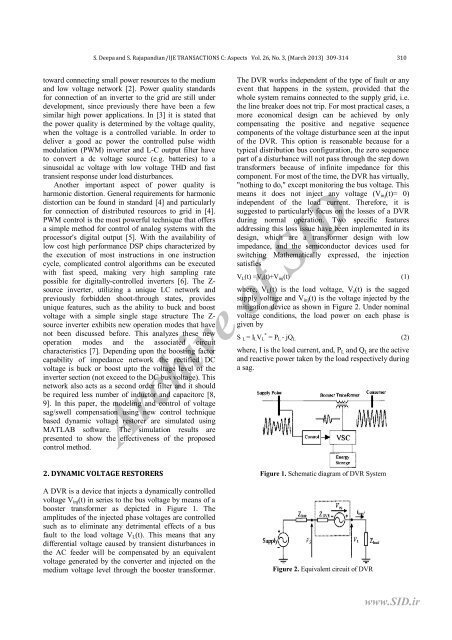
2. DYNAMIC VOLTAGE RESTORERS<br />
A DVR is a device that injects a dynamically controlled<br />
voltage V inj (t) in series to the bus voltage by means <strong>of</strong> a<br />
booster transformer as depicted in Figure 1. The<br />
amplitudes <strong>of</strong> the injected phase voltages are controlled<br />
such as to eliminate any detrimental effects <strong>of</strong> a bus<br />
fault to the load voltage V L (t). This means that any<br />
differential voltage caused by transient disturbances in<br />
the AC feeder will be compensated by an equivalent<br />
voltage generated by the converter and injected on the<br />
medium voltage level through the booster transformer.<br />
Figure 1. Schematic diagram <strong>of</strong> DVR System<br />
Figure 2. Equivalent circuit <strong>of</strong> DVR<br />
www.<strong>SID</strong>.ir