ATVQ Winter 2011 Publication - Space Hardware Club - University ...
ATVQ Winter 2011 Publication - Space Hardware Club - University ...
ATVQ Winter 2011 Publication - Space Hardware Club - University ...

You also want an ePaper? Increase the reach of your titles
YUMPU automatically turns print PDFs into web optimized ePapers that Google loves.
!$# <br />
"% " <br />
<br />
<br />
<br />
<br />
<br />
<br />
<br />
<br />
<br />
<br />
<br />
!
BYERS CHASSIS KITS<br />
Charles Byers K3IWK<br />
5120 Harmony Grove Rd.<br />
Dover,Pa. 17315-3016<br />
Slot antennas original<br />
manufacture by John www.flash.net/~k3iwk<br />
Schaffer, W3SST<br />
Aluminum Chassis Kits and Cabinets and other Enclosures, Small sheets<br />
Of Aluminum and Brass, VHF and UHF Antennas for CW, SSB, ATV,<br />
and Delrin Insulators and Stainless Steel Keepers for 3/16" and ¼" elements.<br />
TV-AMATEUR die deutsche Amateurfunk-Zeitschrift<br />
für ATV bringt in der letzten Ausgabe z. B.<br />
• OSD-Video-Einblendung ganz einfach<br />
• Die Memoiren des ATV-Relais DB0RV<br />
• Ein Besuch bei den Rosenheimern<br />
• DATV-Relais DB0FT mit DVB-T<br />
4 Ausgaben im Jahr für 25.- Euro<br />
bestellen per Fax: 001149 231 48992<br />
oder Internet: www.agaf.de<br />
VHF Communications<br />
<br />
<br />
<br />
<br />
A <strong>Publication</strong> for The Radio Amateur Worldwide<br />
Articles Covering VHF, UHF and Microwaves<br />
Design, Construction and Testing Information<br />
PCBs and Kits Available<br />
Four magazines per year, £19.00 cash or £20.00 credit card, including surface mail delivery<br />
For more information or to subscribe – http://www.vhfcomm.co.uk<br />
email - vhfsubs@vhfcomm.co.uk<br />
OSD-ID+<br />
with Carrier Board<br />
OSD-ID+ is a single channel, standalone<br />
static character and graphic<br />
composite video overlay circuit. This<br />
user programmable device can display<br />
up to 30 columns by 12 rows (NTSC)<br />
or 15 rows (PAL) of text and imported<br />
graphics such as logos directly onto an<br />
incoming composite video source. If no<br />
video input source is available then<br />
OSD-ID+ overlays text and graphics<br />
onto a self-generated background screen.<br />
The overlay can be configured to always<br />
display, appear on a configurable timer<br />
(e.g. every 10 minutes for 30 seconds),<br />
or appear on an external button press.<br />
Included with OSD-ID+ is font editing<br />
software. OSD-ID+ firmware upgrades<br />
are supported via a PC connection.<br />
$129.00<br />
Intuitive Circuits, LLC<br />
Voice: (248) 588-4400<br />
http://www.icircuits.com<br />
If You Move<br />
Please send us your NEW<br />
ADDRESS! We pay 70 cents<br />
for each returned <strong>ATVQ</strong>. And<br />
we are usually nice and send<br />
another copy to your new<br />
address which costs us $1.29.<br />
Please help us from having to<br />
do this. Thanks!<br />
63 Ringwood Road, Luton, Beds, LU2 7BG, U.K. tel / fax +44 1582 581051<br />
http://www.atvquarterly.com<br />
<strong>Winter</strong> <strong>2011</strong> Amateur Television Quarterly 3
AMATEUR<br />
TELEVISION<br />
QUARTERLY<br />
Published by<br />
ATV Quarterly<br />
Amateur Television Quarterly<br />
TABLE OF CONTENTS<br />
Publisher/Managing Editor<br />
Bill Brown - WB8ELK<br />
Publisher/Technical Editor<br />
Mike Collis - WA6SVT<br />
Editor<br />
Art Towslee WA8RMC<br />
Art Director<br />
Jeff Brown - N8UEJ<br />
Subscriptions / Advertising<br />
Mike Collis WA6SVT<br />
P.O. Box 1594<br />
Crestline, CA 92325<br />
(909) 338-6887 - voice<br />
email: wa6svt@atvquarterly.com<br />
Article Submissions / Ad copy<br />
Bill Brown WB8ELK<br />
107 Woodlawn Dr.<br />
Madison, AL 35758<br />
(256) 772-6000 - voice<br />
email: wb8elk@atvquarterly.com<br />
Website:<br />
http://www.atvquarterly.com<br />
Amateur Television Quarterly (ISSN<br />
1042-198X) is published quarterly, in<br />
January, April, July, and October for<br />
$20.00 per year by ATV Quarterly<br />
Magazine, P.O. Box 1594, Crestline,<br />
California 92325. Periodicals Postage<br />
Paid at Crestline, CA and additional<br />
mailing offices. POSTMASTER:<br />
Send address changes to:<br />
Amateur Television Quarterly,<br />
P.O. Box 1594, Crestline, CA 92325.<br />
Amateur Television Quarterly is<br />
available by subscription for<br />
$20.00/yr in the USA; $22.00/yr in<br />
Canada; $29.00/yr elsewhere. Single<br />
issues $5.50/USA; $6.00/Canada;<br />
$8.00 elsewhere.<br />
Sync Buzz Editorial 5<br />
Tripler for 3.4 GHz 6<br />
N8OBU Crossband<br />
ATV Repeater 10<br />
Liberty Middle School Balloon 12<br />
Litchfield ATV Banquet 2010 18<br />
Map to Dayton ATV Dinner 22<br />
ATN-CA <strong>Winter</strong> Meeting 24<br />
A Power Supply for the Ionica<br />
3.4 GHz RF Amplifier 26<br />
Videolynx VM-70X<br />
Transmitter Quick Start 28<br />
Dayton Hamvention ATV<br />
Activities 32<br />
Advertiser Index/<strong>ATVQ</strong> Stores 33<br />
Bill Brown WB8ELK<br />
Mike Collis WA6SVT<br />
Bob Miller W6KGE<br />
Brian Dygert KC8LMI<br />
Bill Brown WB8ELK<br />
Scott Millick K9SM<br />
Art Towslee WA8RMC<br />
Mike Collis WA6SVT<br />
Bob Miller W6KGE<br />
Tom O’Hara W6ORG<br />
Art Towslee WA8RMC<br />
4 Amateur Television Quarterly <strong>Winter</strong> <strong>2011</strong>
Sync Buzz Editorial<br />
- Bill Brown WB8ELK and Mike Collis WA6SVT<br />
ATV Spectrum Landgrab<br />
It seems like it is easier for some<br />
companies to pay lawyers and lobbyists<br />
to grab our amateur radio<br />
70cm ATV spectrum than it is to<br />
hire RF engineers to design TV<br />
transmitters on another frequency<br />
range. Is it really that hard to find<br />
talented RF engineers?<br />
FCC Item:<br />
WP Docket No. 08-63,<br />
ReconRobotics Inc. ATV outfitted<br />
part 90 robot scouts for police and<br />
homeland security is back in the<br />
news. As most of you know the<br />
ARRL, ATN, ATCO, <strong>ATVQ</strong> and<br />
many other ham groups had commented<br />
and objected to allowing the<br />
1 watt (peak sync) three channel<br />
430-450 MHz band robots to be<br />
deployed.<br />
The FCC had approved the request<br />
but additional objections and challenges<br />
were made by the league and<br />
the ham radio community. The FCC<br />
on April 13th modified the report<br />
and order (released April 15th) to<br />
reflect some of the concerns while<br />
tossing others, this modification is<br />
retroactive.<br />
The main changes are in both the<br />
FCC certification tags on the<br />
devices and operation manuals to<br />
say this devise cannot interfere with<br />
and must accept interference from<br />
both federal and non federal (hams)<br />
licensed stations in the 430-450<br />
MHz band.<br />
At least that should stop law<br />
enforcement from coming to your<br />
house and trying to arrest you for<br />
causing QRM to their operations<br />
and allow us some protection if we<br />
get QRM. The channels are as follows,<br />
an agency's first channel allocation<br />
is 436-442 MHz with visual<br />
carrier at 437.25 MHz. The second<br />
channel allocation if they already<br />
have a channel 1 device is 442-448<br />
MHz with video carrier at 443.25<br />
MHz, and the third channel if the<br />
agency already has devices on channels<br />
1 and 2 is 430-436 MHz visual<br />
carrier on 431.25 MHz.<br />
- Bill and Mike<br />
ATVC-4 Plus<br />
Amateur Television Repeater Controller<br />
ATVC-4 Plus is Intuitive Circuit’s<br />
second generation Amateur<br />
Television repeater controller.<br />
ATVC-4 Plus has many features<br />
including:<br />
l Five video input sources<br />
l Four mixable audio input sources<br />
l Non-volatile storage<br />
l DTMF control<br />
l Beacon mode<br />
l Robust CW feedback<br />
l Password protection<br />
l Many more features<br />
For example a major new feature is<br />
four individual sync detection<br />
circuits allowing for true priority<br />
based ATV receiver switching.<br />
$349.00<br />
Intuitive Circuits, LLC<br />
3928 Wardlow Ct. - Troy, MI - (248) 588-4400<br />
http://www.icircuits.com<br />
THE R. F. CONNECTION<br />
“specialist in<br />
R F Connectors and Coax”<br />
http://www.therfc.com<br />
301/840-5477 Order Line 800-783-2666<br />
Fax 301/869-3680<br />
Suite 11, 213 N. Frederick Ave.<br />
e-mail: rfc@therfc.com Gaithersburg, MD 20877<br />
http://www.atvquarterly.com<br />
<strong>Winter</strong> <strong>2011</strong> Amateur Television Quarterly 5
A TRIPLER FOR 3.4 GHZ FM ATV<br />
By Bob Miller, W6KGE<br />
If we build or modify an FM ATV transmitter for<br />
1.2 GHz, and then make a few ‘tweaks’ to get it to<br />
tune to 1.13 GHz, and then add a tripler… Hey!<br />
We’ve got a 3.4 GHz FM ATV transmitter!<br />
Ok, so how do we build a simple tripler that works<br />
with our low power transmitter?<br />
Let me give you a starting point. Modifications<br />
need to be made to match the input and output<br />
signal level requirements, so feel free to experiment<br />
with parts values and amplifier types. Remember,<br />
we are working with FM here, and by it’s very<br />
nature the circuit does not have to be ‘linear‘ so you<br />
can be a little ‘sloppy‘.<br />
the use of surface mount components are important<br />
considerations.<br />
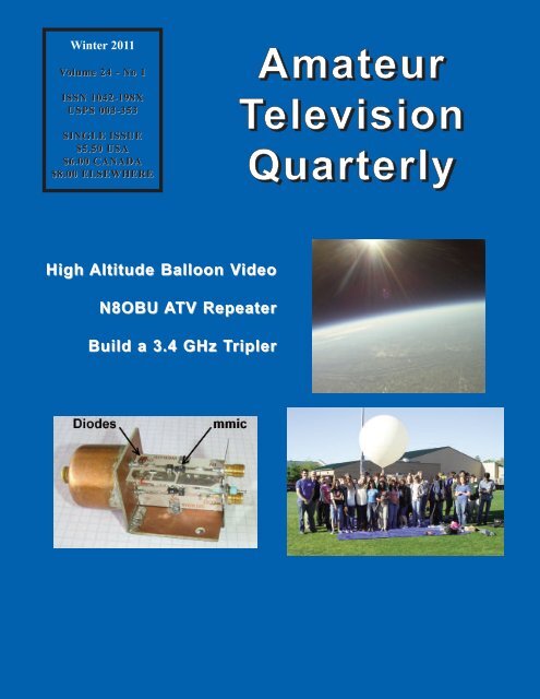
The photos show the completed tripler with the<br />
location of the Schottky diodes and MMIC on the<br />
top 1.13 GHz circuit board. An opposite close up<br />
view shows the PCB and more clearly illustrates the<br />
diode placement and probe entry. The Schottky<br />
diode output is fed into the filter. The 3.4 GHz filter<br />
output is amplified by the bottom board. The<br />
bottom board is mounted at 90 degrees to the top<br />
board.<br />
Let’s review the schematic diagrams. I’ve drawn<br />
two arrangements for this article. The top is for 1.13<br />
GHz transmitters with power outputs of +20 dBm<br />
or greater. The bottom is for those with less than<br />
+10 dBm. The photo illustrates the +10dBm<br />
arrangement with two MMIC’s.<br />
Depending on the output power of the transmitter,<br />
either add some amplification or reduce the power<br />
with a 50 ohm pad. The “R1” and “R2” resistors<br />
shown on the top schematic are chosen to provide<br />
the necessary attenuation. The ARRL Handbook has<br />
been publishing a table of the values of these<br />
resistors for many years. (1)<br />
I used GALI-3+ MMIC amplifiers for this project<br />
because I had some in my ’junk box’ and they<br />
provided the needed gain and output levels.<br />
However, a wide range of MMIC’s are available so<br />
review the spec’s and choose some that will work<br />
for you. (2)<br />
That said, we are working with components at 3.4<br />
GHz. We want them to be stable. Things like<br />
extremely short ground paths for the MMIC’s and<br />
A significant amount of information is available<br />
regarding frequency multiplication using diodes of<br />
various types. In addition, MMIC’s even work as<br />
multipliers.(3) I had some 1N5711 Schottky diodes<br />
in my ‘junk box’ so I used them. Depending on the<br />
diodes chosen, other minor factors are that the<br />
diodes begin to produce nice harmonics somewhere<br />
near the +12 to +16 dBm range at the junction of<br />
the two diodes so plan the design accordingly.<br />
6 Amateur Television Quarterly <strong>Winter</strong> <strong>2011</strong>
The pipe cap filter insertion loss and bandwidth<br />
vary depending on probe lengths. Typical losses are<br />
-2 to -4 dB for bandwidths that pass the desired<br />
frequencies and attenuate unwanted harmonics to<br />
acceptable levels. I found that by using UT-085 or<br />
UT-141 rigid coax for the probes and carefully<br />
positioning the RF pc boards, the center conductor<br />
can be pulled in and out to ’fine tune’ the loss and<br />
bandwidth.<br />
Start your project by assembling two circuit boards<br />
for the portions of the circuit before and after the<br />
filter.<br />
I use 0.030 Taconic RF-35 which is a ’microwave’<br />
type PTFE material, rather than the standard<br />
fiberglass PC board for the circuit. It’s not primarily<br />
because of the ’losses’ in fiberglass at microwave<br />
frequencies but because it cuts well with a knife! I<br />
like to make my own pc boards. Commercially<br />
produced microwave boards are designed with lots<br />
of ’through plated’ holes for low impedance<br />
grounding. Plating ’homebrew’ pc boards is not<br />
practical so as a alternative, generally use ‘z-wire’<br />
grounding.(5)<br />
Since high gain, microwave MMIC’s need<br />
exceptional ground paths for stability, I use the<br />
following method.<br />
I use the ‘tools’ in the following photo:<br />
From the top: A wooden dowel sharpened like a<br />
pencil to use as a ‘burnishing’ tool. An abrasive<br />
pad, like ‘Scotchbrite’ is used to clean the copper<br />
foil just before soldering. Use an ‘Exacto’ knife<br />
with a very small blade to cut a piece of 0.001”<br />
Cont. on Page 8
Finish the ground by soldering the foil to the<br />
backside of the double copper sided board. The<br />
installation should be flat enough to allow the<br />
MMIC to be soldered to the board later.<br />
copper foil, 0.10” wide. Place the PTFE board on a<br />
hard surface and make a series of light then heavier<br />
cuts with the small ‘Exacto’ knife until it’s cut<br />
completely through the board for grounding. The<br />
slot shown in the photo is approximately 0.15” long.<br />
For the less critical grounds drill holes for ‘z-wires’<br />
at other board locations. Use a # 26 or #28 fine<br />
stranded silver plated Teflon insulated wire for this<br />
process rather than the solid wire that is often used.<br />
Tin the end of a 5” piece of the stranded wire, and<br />
strip all of the insulation, leaving the remainder as<br />
loose strands. Then feed the tinned end of the wire<br />
through the hole leaving a very short length of the<br />
un-tinned end. Spread the un-tinned ends and solder<br />
them to the board. Next, cut the wire to a very short<br />
length on the other side of the board. Flatten, spread<br />
the strands and solder them to the board. This leaves<br />
a very flat, slight bump rather than the large bump<br />
caused when solid wire is used. The relatively flat<br />
bump allows a heat sink or solid metal plate attach<br />
to the board with screws without unduly flexing the<br />
board.<br />
The filter assembly is next. An excellent article has<br />
been written regarding ’pipe cap’ filters.(4) This is a<br />
widely available reference published by the ARRL.<br />
I encourage you to read it rather than spending<br />
pages here on details. Here are some items that are<br />
not discussed.<br />
Measure and insert a freshly cleaned piece of foil<br />
into the slot. Adjust the amount of foil that<br />
protrudes through the PTFE board by using a shim<br />
of desired thickness under the board leaving the<br />
area under the slot for the foil to protrude. Then,<br />
using the burnishing tool, fold the foil over and<br />
burnish it flat. Solder it in place, and clean the board<br />
with flux remover.<br />
Start by installing the probes for the pipe cap filter<br />
using double sided copper fiberglass pc board. Cut<br />
the outer coaxial shield just long enough to solder to<br />
both sides of the double sided PC board.<br />
Next, the pipe cap is drilled and tapped to for a 1”<br />
long #10-24 brass round head machine screw. A<br />
8 Amateur Television Quarterly <strong>Winter</strong> <strong>2011</strong>
long will damage the pc board and may ‘unsolder’<br />
the probes).<br />
Next, as shown in the photo, the RF circuit boards<br />
are attached by soldering the copper ground plane<br />
side of the boards to the filter and soldering the<br />
probes to the strip lines on the RF boards.<br />
#10-24 hex nut is used to ‘jam’ the brass machine<br />
screw. The screw and nut will be installed later.<br />
(The nut is tightened against the copper cap after<br />
the screw is adjusted to tune the filter).<br />
The open ends of pipe caps are often irregular. They<br />
can be ‘squared up’ by placing a piece of medium<br />
grit sandpaper on a flat surface and working the<br />
pipe cap back and forth to sand the opening flat.<br />
Use a piece of sandpaper or a ‘Scotchbrite’ type of<br />
pad to clean the inside and outside of the pipe cap.<br />
Position it over the probes on the pc board being<br />
careful to correctly center it. Use a metal ’C-clamp’<br />
to keep the pipe cap and pc board together.<br />
Finally, supply DC power and tune the filter. A<br />
spectrum analyzer is best for this. With the filter<br />
properly adjusted the tripler provides a ‘clean’<br />
output with unwanted harmonics down at least -40<br />
dB from the third harmonic.<br />
( 1 ) Table 7.56, Pi-Network Resistive Attenuators<br />
(50 ohm), The ARRL Handbook for Radio<br />
Communications 2006, pp 7.47.<br />
( 2 ) www.minicircuits.com and others.<br />
( 3 ) J. Davey, “Frequency Multipliers Using<br />
MMICs”, UHF/Microwave Projects Manual, Vol.<br />
1, pp 5-13 to 5-15.<br />
( 4 ) K. Britain, “Cheap Microwave Filters From<br />
Copper Plumbing Caps” The ARRL<br />
UHF/Microwave Projects Manual, Vol. 1, pp 6-6 to<br />
6-7.<br />
( 5 ) ‘z-wire grounding’ = Holes are drilled through<br />
the pc board at closely spaced intervals and as close<br />
to components that require grounding as possible.<br />
Bare copper wire is then pushed through the holes<br />
and soldered from the top side of the board to the<br />
bottom continuous grounding foil.<br />
<strong>ATVQ</strong><br />
Use ’vise-grip’ pliers and bench vise to hold the<br />
assembly while heating the pipe cap (NOT THE PC<br />
BOARD) with a propane torch. Check temperature<br />
by touching the joint between the pipe cap and pc<br />
board with solder. As soon as the solder begins to<br />
flow, remove heat from the pipe cap and run the tip<br />
of the solder around the seam between it and the<br />
board. It’s not necessary to use a lot of solder here.<br />
Use just enough to completely solder the perimeter<br />
of the cap to the board. Then use a wet cloth to cool<br />
the pipe cap. (Remember, too much heat for too<br />
http://www.atvquarterly.com<br />
<strong>Winter</strong> <strong>2011</strong> Amateur Television Quarterly 9
N8OBU Crossband ATV Repeater<br />
- Bryan Dygert KC8LMI<br />
The N8OBU ATV repeater is located<br />
15 miles southwest of Lansing,<br />
Michigan. It was built and is maintained<br />
by Bruce KA8ZXX, Bryan<br />
KC8LMI,and Mike N8OBU. The<br />
repeater antennas are on Mike’s 185<br />
foot Rohn 25G tower in his backyard.<br />
The ATV repeater is co-located<br />
with his 444.575 and 927.525 FM<br />
voice repeaters. The input is 439.250<br />
lvsb horizontal omni and the output<br />
is 910.250 vertically polarized running<br />
400 watts PEP to an 8dB commercial<br />
900MHz stick at 170 feet,<br />
fed with 1-1/4" hardline. The 900<br />
antenna is side mounted on the west<br />
leg of the tower. The receive antennas<br />
are two homemade rib cages vertically<br />
stacked at 160 feet with an<br />
approximate gain of 7 dBd and are<br />
mounted on the south leg. We are using a half-wave<br />
power divider to combine the rib cages. We recently<br />
put up a tower-mounted Advanced Receiver Research<br />
RF-switched preamplifier. The receive system is fed<br />
with 1/2" hardline. There is a two meter ground<br />
plane at 10 feet for the control receiver. The repeater<br />
is made up of the following:<br />
- ATVR-4 439.25 lvsb synthesized ATV receiver<br />
- ATVC-4 plus controller<br />
- TXA5-33 1.5 watt 33 cm exciter (8dB attenuation<br />
before amp input)<br />
- Glenayre linear power amp (400 watts sync tips)<br />
- Homemade 7-pole lvsb filter (434.5-440.5MHz)<br />
- West Mountain Radio Rig Runner<br />
- Sandisk digital photo viewer for the ID generator<br />
- Homemade latch board for DTMF control of preamp<br />
on/off state and OSD video<br />
- Icom VHF control receiver<br />
- Repeater room camera on port 3<br />
The repeater has been performing well, as Brian<br />
K8IGU in Lucky, Ohio is getting into it almost every<br />
morning. Ron K8DMR reports seeing it up to P3 levels<br />
over in Jenison, Michigan approximately 80 air<br />
miles away using a 15-element beam at only 18 feet.<br />
The repeater is in normal repeat mode 24/7. I have<br />
also setup a BATC.TV streaming account under<br />
N8OBU ATV REPEATER, however, streaming is not<br />
on 24/7.<br />
There are around seven to eight ATVers within the<br />
coverage area that have 900MHz receive capability.<br />
10 Amateur Television Quarterly <strong>Winter</strong> <strong>2011</strong>
Two vertically stacked ribcage antennas at<br />
the 160-foot level on the tower<br />
910.25 MHz transmit antenna on the left,<br />
439.25 MHz dual ribcage receive antenna<br />
on the right.<br />
Mast-Mounted ARR preamp<br />
Antenna height is worth the climb<br />
http://www.atvquarterly.com<br />
<strong>Winter</strong> <strong>2011</strong> Amateur Television Quarterly 11
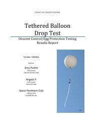
Liberty Middle School Balloon<br />
- Bill WB8ELK<br />
Liberty Middle School eighth grade science class students with their high altitude balloon<br />
On April 13th, <strong>2011</strong> members of the UAH <strong>Space</strong><br />
<strong>Hardware</strong> <strong>Club</strong> launched a balloon carrying eighthgrade<br />
student experiments from Liberty Middle<br />
School in Madison, Alabama to the edge of <strong>Space</strong>.<br />
The <strong>Space</strong> <strong>Hardware</strong> <strong>Club</strong> (spacehardware.uah.edu) is<br />
funded mostly by Alabama <strong>Space</strong> Grant and is comprised<br />
of volunteer UAH (<strong>University</strong> of Alabama in<br />
Huntsville) students who do a variety of BalloonSat<br />
and satellite design projects. They often do outreach<br />
programs with local schools which is a great way to<br />
inspire students to pursue a career in space, science<br />
and technology. This is a low-cost way to allow students<br />
to send their experiments into a space-like environment<br />
and allows them to run their very own space<br />
program right from their school.<br />
This flight flew four student experiments from Ms<br />
Lyons’ eighth-grade science class. They flew a variety<br />
of things to see what happened to them during their<br />
journey into the sub-zero temperatures and near-vacuum<br />
of the stratosphere.<br />
One experiment consisted of markers, pens and even<br />
12 Amateur Television Quarterly <strong>Winter</strong> <strong>2011</strong>
lightbulbs to see if they still worked after the flight.<br />
One payload was covered with solar cells and their<br />
performance was measured with an internal Arduino<br />
board that stored the solar cell data onto an SD memory<br />
card. After flying over 85,000 feet, being recovered<br />
about 60 miles downrange and banging around<br />
in my trunk for two days, it was still operating after<br />
54 hours!<br />
The other payloads contained things like bread,<br />
banana and apple slices, a calculator, a can of soda<br />
and a bag of popcorn.<br />
One of the payloads had party balloons filled with a<br />
variety of gases to see which ones would pop during<br />
the flight.<br />
The flight carried two APRS transmitters as well as<br />
two high-definition camcorders. The Sony Handicam<br />
was in the last payload pointed straight up at the balloon<br />
and caught one of the party balloons popping<br />
near the top of the flight. It also recorded amazing<br />
video of the main weather balloon bursting at 85,782<br />
feet.<br />
Liberty Middle School students prepare for<br />
liftoff of their science experiments<br />
It was a perfect morning with clear skies and dead<br />
calm conditions. A large crowd of students came out<br />
to the ballfield to watch the picture perfect liftoff.<br />
The balloon flew across the city of Huntsville with<br />
my horizon still camera payload taking beautiful<br />
snapshots of the city and nearby Lake Guntersville.<br />
After reaching peak altitude, the balloon popped and<br />
everything parachuted down to land in a pasture just<br />
each of Geraldine, Alabama.<br />
Jason Winningham KG4WSV and a group from the<br />
<strong>Space</strong> <strong>Hardware</strong> <strong>Club</strong> tracked the balloon via APRS<br />
and made the relatively easy recovery from the pasture.<br />
Trust me, it’s usually not this easy. We often<br />
have to climb tall trees and hike through the wilderness.<br />
But every once in awhile Mother Nature lets us<br />
off easy.<br />
Dramatic footage of the balloon burst at<br />
85,782 feet as captured by the UAH SONY<br />
Handicam<br />
Cont. on Page 14<br />
http://www.atvquarterly.com<br />
<strong>Winter</strong> <strong>2011</strong> Amateur Television Quarterly 13
Above and Right: The Hero HD camcorder<br />
payload<br />
The GoPro Hero HD camcorder<br />
I have flown quite a variety of small camcorder units<br />
on balloons. The units I have had the most success<br />
with are the Flip Ultra pocket camcorder units.<br />
Although they make an HD version, most of my previous<br />
flights have used the standard definition modes.<br />
I have filmed some spectacular footage with the Flip,<br />
but they have a few drawbacks. Most notably the<br />
memory is built into the unit and there is no way to<br />
extend it with an external memory card. The limit for<br />
most Flip units is two hours record time and that usually<br />
means that I miss the last few minutes of a typical<br />
balloon mission and the landing can be the most<br />
exciting part. Also, the Flip Ultra HD version does<br />
720p Hi-Definition but won’t do 1080p. The last<br />
thing to note is that apparently the Flip series may be<br />
discontinued due to competition from the newer cell<br />
phones with built-in cameras.<br />
After doing some shopping for a replacement camera<br />
I finally settled on the GoPro Hero HD camera<br />
(www.gopro.com). Fortunately, I had recently<br />
received my new camcorder unit just prior to this<br />
The GoPro Hero HD hi-def camcorder<br />
flight and managed to hitch a ride with the Liberty<br />
Middle School flight at the last minute. I quickly cobbled<br />
together a payload and hooked it near<br />
the parachute pointing out at the horizon. The neat<br />
thing about the Hero HD camera is that with its<br />
intended audience of extreme sports enthusiasts, it<br />
also is perfectly designed for high altitude ballooning,<br />
R/C airplanes, ATV Hatcams and would work well in<br />
14 Amateur Television Quarterly <strong>Winter</strong> <strong>2011</strong>
least 3 hours record time which is more than enough<br />
to capture a full balloon mission from takeoff to landing.<br />
I like the fact that there is no LCD screen built into<br />
the camera (an optional screen snaps on for viewing).<br />
This eliminates both weight and dramatically reduces<br />
current drain to allow longer record times. A simple<br />
LCD text screen on the front is easy to use to set the<br />
camera up and even allows you to invert the image if<br />
you want to mount the camera upside down. Another<br />
great feature is the “one-button record” option. I can<br />
start it up in a preselected mode from the outside of<br />
my payload just by pushing on the front-mounted<br />
power on button.<br />
One more nice feature that is perfect for ATV use is<br />
its capability to hook a cable to the camera to output<br />
live video to a video transmitter at the same time that<br />
it is recording to the SDHC card.<br />
Student experiments just prior to liftoff<br />
a tiny ATV portable system.<br />
It weighs in at a mere 3.5 ounces (5.0 ounces with the<br />
optional backpack battery). The Hero comes in a nice<br />
rectangular package which makes mounting it into a<br />
styrofoam box quite easy. Although the Hero comes<br />
with a plastic housing to protect it from the elements,<br />
I opted to fly it with it’s lens exposed to eliminate<br />
fogging issues due to the temperature extremes it<br />
would encounter during the flight.<br />
It can do video recording in a wide range of resolutions<br />
all the way up to 1080p mode. If you want to<br />
just take still frames with it, you can set it up to take<br />
5 megapixel sequential stills from between 1 second<br />
to 1 minute intervals for as long as the battery lasts or<br />
until the camera memory card fills up. With the capability<br />
of using a 32 gigabyte SDHC card along with<br />
the backpack battery (which doubles the battery life),<br />
I was able to take thousands of photos at a 10 second<br />
interval for upwards of 5 hours during this flight.<br />
Running the Hero at 1080p mode hi-def video with<br />
that same size memory card will provide you with at<br />
Keep in mind that the lens is fixed and depending on<br />
the mode will be very wide angle. As a result, you’ll<br />
have to make sure the camera lens extends beyond the<br />
edge of your container (which explains what Gary<br />
Dion N4TXI called the “looking out the door of a styrofoam<br />
igloo” look of the photos starting on page 16.<br />
The still frames shown on the next two pages were<br />
taken by the Hero HD payload from launch to landing<br />
at 10,000 foot intervals.<br />
The camera was exposed to temperatures of -40 deg<br />
C and below and managed to not only survive but<br />
was still running when it was recovered from the pasture.<br />
More photos on Page 16<br />
http://www.atvquarterly.com<br />
<strong>Winter</strong> <strong>2011</strong> Amateur Television Quarterly 15
Liftoff<br />
10,000 feet over HSV Int’l Airport<br />
20,000 feet 30,000 feet<br />
40,000 feet 50,000 feet<br />
16 Amateur Television Quarterly <strong>Winter</strong> <strong>2011</strong>
60,000 feet 70,000 feet<br />
80,000 feet 85,000 feet<br />
200 feet - about to land 4 feet - taken a split second before landing<br />
http://www.atvquarterly.com <strong>Winter</strong> <strong>2011</strong> Amateur Television Quarterly 17
Litchfield ATV Banquet 2010<br />
- Scott Millick K9SM<br />
Twenty-Fifth Annual ATV banquet at the Ariston Restaurant in Litchfield, IL<br />
TWENTY-FIFTH ANNUAL<br />
ATV BANQUET<br />
A beautiful 45-degree day provided<br />
a pleasant trip for those<br />
traveling to the Silver<br />
Anniversary celebration of the<br />
Central Illinois/St. Louis Area<br />
Amateur Television <strong>Club</strong>'s banquet<br />
at the Ariston Restaurant in<br />
Litchfield, Illinois. This location<br />
serves as a central meeting point<br />
for club members attending from<br />
the Bloomington, Mt. Vernon,<br />
Springfield, Champaign, Canton,<br />
Macomb, Illinois and St. Louis,<br />
Missouri areas<br />
This dedicated group of ATV operators once again<br />
arrived for another evening of renewing friendships<br />
and meeting new members with 42 members attending<br />
this year.<br />
Memories of times past<br />
As members arrived the talk about ATV openings,<br />
contesting, and equipment reverberated throughout<br />
the room.<br />
18 Amateur Television Quarterly <strong>Winter</strong> <strong>2011</strong>
wives. Everyone present was in an area from<br />
Springfield, Illinois to St. Louis, Mo. It expanded to<br />
include other areas through the years until today<br />
where it encompasses about a 120 mile radius from<br />
Litchfield, Il. Many great programs were presented,<br />
most by the members themselves. Two examples were<br />
a demonstration of mechanical TV by Peter Yanczer<br />
K0IWX and a talk about phasing by Bob Heil,<br />
K9EID. It brought back a lot of memories of the past<br />
and those who participated in ATV.<br />
A Trivia Contest was held with the tables competing<br />
with each other to answer 25 questions presented by<br />
K9SM about ATV, amateur radio and the club. Every<br />
table was a winner as it also provided a time for<br />
reflection about the hobby and those who are members.<br />
The famous prize drawing followed which included a<br />
Bird wattmeter. As always the drawing provided a lot<br />
K9SM on left with K9IDQ accepting the special<br />
award for K9KKLwho was unable to<br />
attend<br />
The group was called to order at 5 PM by Scotty<br />
K9SM and after a few announcements the clatter of<br />
dishes, glasses, utensils and chit chat continued<br />
throughout the course of a great meal and delicious<br />
desserts.<br />
As this was the 25th anniversary of the banquet there<br />
was no ATV Operator of the Year awarded and no<br />
formal program given.<br />
Instead it was time to remember about times past and<br />
those who were active in the early days of ATV and<br />
their stories. Also remembered was those who are no<br />
longer with us and some of the early equipment that<br />
was used.<br />
The original banquet began in the same restaurant<br />
location as it is held today. There were 12 people present:<br />
K9SM, W9JF (WB9ENR), W9BH (KB9DU),<br />
KD0LO, K9KKL and WB0ZJP (deceased) and their<br />
KO0Z and a whopper of a story.<br />
Cont. on Page 20<br />
<strong>Winter</strong> <strong>2011</strong> Amateur Television Quarterly 19
of fun and laughs. The first person's name drawn had<br />
their choice of any three of any of the 150 plus prizes<br />
on the first round. After that every person whose<br />
name was called could select 3 prizes from the prize<br />
table or take a prize from someone who had already<br />
chose one. That person then selects a replacement<br />
from the prize table. This led to some of the main<br />
prizes changing hands over a dozen times. Everyone<br />
left with at least four prizes. The Bird wattmeter was<br />
won by Mel Whitten K0PFX from St. Louis MO.<br />
After the drawing more visiting followed and<br />
farewells were said. Everyone made their way home<br />
and are looking forward to the next banquet scheduled<br />
for November 13, <strong>2011</strong>.<br />
----------------------------------------------------------------<br />
The above information is dated 4-10-11. Further<br />
information or questions should be directed to:<br />
Central Illinois/St. Louis Area ATV <strong>Club</strong><br />
Scott Millick K9SM<br />
222 N. Jackson St.<br />
Litchfield, Illinois 62056<br />
217 324-2412<br />
smillick@wamusa.com<br />
Which Prize to Take?<br />
Thinking Digital ATV?<br />
Two Digital ATV presentations from the 2009<br />
ARRL/TAPR Digital Comm. Conference are now<br />
on DVD from ARVN. Also, WB8ELK talks ballooning,<br />
and 12 more high-tech seminars<br />
on the six-DVD set. Free<br />
preview on our web site!<br />
What’s<br />
happening<br />
at your next<br />
club meeting?<br />
ATV<br />
TV<br />
more info, free previews at:<br />
www.ARVideoNews.com<br />
e-mail kn4aq@arvideonews.com<br />
available only on<br />
20 Amateur Television Quarterly <strong>Winter</strong> <strong>2011</strong>
H ar<br />
l an<br />
Tech<br />
hno<br />
l o<br />
gie<br />
s<br />
rtant!<br />
elevision<br />
activities,<br />
projects, ATV DX information, SSTV,<br />
and other amateur<br />
radio video related<br />
activities, SUBSCRIBE NOW TO:<br />
Amateur<br />
Television Quarterly<br />
Fun<br />
To ORDER:<br />
things!<br />
www.atvquarterly.com<br />
wa6svt@atvquarterly.com<br />
(909) 338-6887<br />
Rate<br />
USA<br />
Canada/<br />
Mexico<br />
DX<br />
1 year<br />
$20 $22<br />
$29<br />
2 years<br />
$38 $42<br />
$57<br />
3 years<br />
$55 $61<br />
$84<br />
4 years<br />
$71 $80<br />
$111<br />
5 years<br />
$87 $99<br />
$136<br />
Life<br />
$399 $439<br />
$579<br />
ATV Secrets<br />
Vol<br />
I & II On<br />
CD<br />
ATV Secrets<br />
is a great place to start your ATV adventure!<br />
Volume<br />
I has 64 pages, tightly<br />
packed<br />
with information<br />
covering<br />
all aspects of getting started,<br />
where to find<br />
activity, equipment,<br />
how to DX, and answers<br />
frequently<br />
asked<br />
questions<br />
about<br />
power, antennas,<br />
vestigial<br />
sideband operation<br />
and<br />
more. Everything the beginner<br />
in ATV needs!<br />
Volume<br />
II is a mammoth book with<br />
292 pages of technical<br />
material.<br />
More than 40 authors<br />
present<br />
over 90 technical<br />
projects<br />
and theory topics to fully<br />
acquaint<br />
anyone<br />
from novice<br />
to expert<br />
in the how and what<br />
of TV,<br />
video, and<br />
ham TV.<br />
Divided into<br />
11 chapters, the book presents<br />
tested projects<br />
for<br />
all<br />
areas of<br />
interest<br />
in ham TV including<br />
antennas,<br />
amplifiers,<br />
repeaters,<br />
receivers,<br />
transmitters, video accessories, and more!<br />
Volume<br />
II<br />
is sold out in the paper<br />
version,<br />
but available<br />
on<br />
CD.<br />
ATV<br />
Secrets Volume One<br />
(paper) $8.95<br />
Shipping<br />
USA - $4.50<br />
ATV Secrets I & II on<br />
CD $25.00<br />
Shipping<br />
USA - $6.00
ATV Friday Night Dinner 2010 <strong>2011</strong> The ATV Friday night dinner and discussion will be<br />
held on Hamvention Friday from 7 till 10PM at Roush's Restaurant 305 W Main St. in Fairborn,<br />
OH 45324 (at the north end of Wright Patterson airfield runway). The dinner menu is varied,<br />
moderately priced and ordered separately. We will enjoy a sit down dinner then have speakers<br />
talk about various ATV topics. We will also include door prizes for those present. The meeting<br />
terminates at about 10PM.<br />
Directions: Take I-75 north then I-70 east. Exit SR 235/ SR4 south (Fairborn exit). South on 235<br />
about 1 mile then left on Chambersburg Road (east & still SR235 past airport runway). Right<br />
on N. Broad Street for about 10 blocks. Turn left on W. Main Street for 3 blocks to Miller Ave.<br />
Roush's is on corner of W. Main and Miller. Parking in rear. Roush’s Restaurant. 305 W. Main<br />
street, Fairborn, OH 1-937-878-3611 GPS (39-49-19-N) X (84-01-30-W)<br />
22
ATN-CA <strong>Winter</strong> Meeting<br />
- Mike Collis WA6SVT Photos by George AC6RB<br />
The California chapter of Amateur<br />
Television Network held it’s annual<br />
winter brunch and business meeting<br />
February 19th, <strong>2011</strong> in Irwindale<br />
California. We started with brunch at<br />
11AM with 26 members from the<br />
California chapter and three members<br />
from the Arizona chapter.<br />
The meeting was brought to order at<br />
12 noon by Don Hill KE6BXT the<br />
ATN-CA president. Repeater system<br />
reports were made by Mark W6MAF,<br />
Rod WB9KMO, Allan W6IST, and<br />
Mike WA6SVT. Peter KD7OIW the<br />
Arizona chapter president was introduced<br />
along with Bob W8ARZ and<br />
Tom KE7QK that drove seven hours<br />
to attend the meeting from Phoenix<br />
Arizona. Peter then gave a report on<br />
the Arizona chapter and their repeater<br />
system.<br />
We had a break and dues renewals were made during<br />
this time too. Following the break, Don KE6BXT presented<br />
two presidents awards this year for technical<br />
service at our repeater sites. Mark W6MAF and Bob<br />
W6KGE received the awards. Mike WA6SVT passed<br />
out <strong>ATVQ</strong>’s first all color print magazines to all and<br />
talked about the magazine.<br />
GHz FM and how much better it was than the higher<br />
powered VSB signal on 919 MHz.<br />
We all had a great time socializing at the meeting and<br />
look forward to our summer BBQ social later this summer.<br />
73,<br />
Mike WA6SVT<br />
Nominations were taken for officer elections and each<br />
nominee gave a short talk. Elections followed and Our<br />
new officers are; Tom Board WB6HYH President,<br />
George Migliarini AC6RB V.P. The Sec/Tres is<br />
appointed, Mike WA6SVT fills the post.<br />
Some members brought equipment to show to the<br />
group. Bob W6KGE talked about the new 3380 MHz<br />
FM transmitter he built up and helped install with<br />
Chuck WA6FGK and Allan W6IST for Oat Mountain’s<br />
new FM output to compliment the existing 919.25<br />
MHz VSB output. Bob talked about the coverage on 3<br />
24 Amateur Television Quarterly <strong>Winter</strong> <strong>2011</strong>
New ATN-CA officers from left: Tom WB6HYH President, George AC6RB Vice President, Mike<br />
WA6SVT Sec/Tres and Trustee of W6ATN and Rod WB9KMO Trustee of Santa Barbara repeater.<br />
<br />
<br />
<br />
<br />
<br />
<br />
<br />
<br />
<br />
<br />
<br />
<br />
<br />
<br />
<br />
<br />
<br />
<br />
<br />
<br />
<br />
<br />
<br />
<br />
<br />
<br />
<br />
<br />
<br />
<br />
<br />
<br />
<br />
<br />
<br />
<br />
<br />
<br />
<br />
<br />
<br />
<br />
<br />
<br />
<br />
<br />
<br />
<br />
<br />
<br />
<br />
<br />
<br />
<br />
<br />
<br />
<br />
<br />
http://www.atvquarterly.com<br />
<strong>Winter</strong> <strong>2011</strong> Amateur Television Quarterly 25
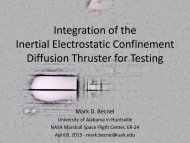
A POWER SUPPLY FOR THE IONICA 3.4GHz RF AMPLIFIER<br />
By Bob Miller, W6KGE<br />
As part of an upgrade to our Oat Mountain ATV<br />
repeater, we recently installed an Ionica 3.4 GHz<br />
RF amplifier as part of our FM ATV transmitter.<br />
Many years ago, Ionica was licensed, to provide<br />
Fixed Wireless Services, in parts of the UK. After<br />
producing a number of RF amplifiers for 3.4 GHz,<br />
the license was re-assigned. As a result, a large<br />
number of amplifiers were no longer needed. They<br />
are often available on the surplus market. The<br />
amplifier produces approximately 15 watts output<br />
with less than 7 milliwatts of drive.<br />
The power supply provides all the necessary<br />
voltages. More importantly, it must never supply<br />
the 10 vdc if the bias voltage is reduced or lost.<br />
To reduce supply complexity, a 12VDC 18A<br />
switching power supply is used for the main dc<br />
power to the regulator and control portion. Almost<br />
any good quality supply will work. The DC supply<br />
is shown here with cover removed.<br />
Photo of Ionica 3.4 GHz RF amplifier with cover<br />
removed. Left side is power and control, right side<br />
is RF section. RF input is shown at bottom right.<br />
Amplifiers of this type, typically require several<br />
different regulated voltages. Power is supplied by a<br />
standard 15 pin D-connector.<br />
Pin 1 = Used for output of an ‘on-board’ RF power<br />
detector. (approx. 6.5 volts at full power output).<br />
Pin 2,3 = Unconnected.<br />
Pin 4 = +5VDC. (Push-to-Talk / Mute function?).<br />
Pin 5 = -12VDC.<br />
Pin 6,13,14 = “0 volts”. (Negative return for the<br />
major +10VDC power. )<br />
Pin 7,8,15 = +10VDC power.<br />
Pin 9 = Ground return for RF power detector.<br />
Pin 10 = Output from on-board temp. sensor.<br />
Pin 11 = Output from on-board error detect.<br />
Pin 12 = +12V @ 30mA. (must not be >12VDC)<br />
From here, look at the schematic. Because I<br />
designed the supply to match the devices available<br />
from my ‘junk box’ a bit of explanation is in order.<br />
12VDC power from the main supply is fed directly<br />
to a DC-DC converter. The schematic uses the<br />
converter I had available. As a result, I had to add a<br />
negative 12 volt regulator to the circuit. (A DC-DC<br />
converter designed for +12VDC input and regulated<br />
-12VDC output would work also eliminating the<br />
need of the 79L12). Regardless of which method is<br />
used, the output of this portion of the circuit is what<br />
controls the power relay that then controls the<br />
9.6VDC output to the RF amplifier.<br />
Two Linear Technology LT1084CT regulators are<br />
used in parallel in this circuit. To insure current<br />
sharing between the two regulators, two<br />
approximately 0.015 ohm resistors are made by air<br />
coil winding (2) 18” of #20 enameled copper wire.<br />
(Editor's note; this power supply will also work very well for<br />
powering up used ITFS/MMDS FET power amplifier modules<br />
for use on 2.4 GHz ATV, Mike WA6SVT)<br />
26 Amateur Television Quarterly <strong>Winter</strong> <strong>2011</strong>
Because of my ‘junk box’ parts, I used a lot of<br />
surface mount 47 uF tantalum capacitors in parallel<br />
at various locations on the schematic. These can be<br />
replaced with your capacitor choice with at least the<br />
total amount of combined capacitance shown.<br />
The bottom of the regulator board showing the heat<br />
sinks, copper coil resistors, power relay, smaller<br />
regulators and the DC-DC converter module.<br />
The top of the regulator board, showing the voltage<br />
status LED’s, parallel surface mount tantalum<br />
capacitors and the extra wide copper foil traces for<br />
the higher current portions of the circuit.<br />
(A portion of the Ionica RF amp is shown at the<br />
bottom right of this photo with heat sink attached).<br />
A forced air fan is used to cool the 12V switching<br />
power supply, regulator and control board.<br />
<strong>ATVQ</strong><br />
http://www.atvquarterly.com<br />
<strong>Winter</strong> <strong>2011</strong> Amateur Television Quarterly 27
P. C. Electronics 2522 Paxson Lane Arcadia CA 91007-8537 USA ©<strong>2011</strong><br />
Tel: 1-626-447-4565 m-th 8am-5:30pm pst (UTC - 8) Tom (W6ORG) & Mary Ann (WB6YSS)<br />
Email: ATVinfo @ hamtv.com<br />
Web site: http://www.hamtv.com<br />
Videolynx VM-70X Transmitter Quick Start<br />
Your transmitter comes set for around 1/2 Watt pep output which allows you to connect up DC power and RF Out<br />
to almost immediately put a signal out on the air. Connect a red insulated #18-22 wire (Radio Shack 278-567) to<br />
the 12V solder pad and a black one to the adjacent Gnd solder pad. Always double check that red is connected to<br />
the positive output of the 11 to 13.8Vdc power source, you can damage the module if reversed.<br />
You can use batteries, but a regulated 13.8 Vdc power supply works best. Connect a 50 Ohm<br />
dummy load to the RF Out SMA jack or 70cm whip antenna that has a SMA plug on it. Set the<br />
frequency digiswitch to 427.25 MHz and internal video: 2 is ON (1) all others OFF (0). Connect<br />
an external 70cm antenna to a TV set to cable channel 58 or downconverter to 427.25 MHz.<br />
We stock a F male to N jack adapter to connect your TV directly to<br />
low loss 1/2” size 50 Ohm coax with N plugs - 50/75 Ohm miss<br />
match is negligible. We also stock a SMA male to N jack adapter<br />
to connect the 50 Ohm 70cm antenna coax to the VM-70X.<br />
In order to connect up your camera and line audio, you can get BNC and RCA jacks from Radio<br />
Shack or Mouser and run a shielded cable from each to the Vin video and Ain audio input solder<br />
pads on the VM-70X. It is easiest is to just cut off one end of a existing BNC and/or RCA<br />
shielded cable that mates with your camera jacks. Strip the cut end about a half inch and solder<br />
the centers and Gnd shields to the solder pads. To transmit the video from the camera instead of<br />
the internal test video pattern, reverse the 4 digiswitch settings with 2 off and the others on.<br />
427.25 MHz Test<br />
0 1 0 0<br />
Turn on the DC power and look for the two white vertical bar test pattern and tone on the TV for no more than 5<br />
minutes unless you have mounted a sufficient heat sink to the bottom plate - see the other application note pages.<br />
A one to two second delay for the RF to come up is normal. With inside antennas, you may also note some picture<br />
instability in the picture due to TV overload and/or multipath. If you are receiving the test pattern and audio, turn<br />
off the DC power and reset the frequency digiswitches for transmitting video from your camera. Cameras and<br />
mics can be RF susceptable so experiment with keeping the camera far enough away from the transmitting antenna.<br />
N<br />
F<br />
N<br />
SMA<br />
427.25 MHz Cam<br />
1 0 1 1<br />
Before connecting to a good outside 70cm antenna with a SWR of no more than 2:1, find out on your local two<br />
meter ATV talk back frequency what ATV antenna polarity is being used and which of the 4 ATV frequencies is<br />
used in your area - 144.34 and 146.430 MHz simplex are common. Only two 70cm ATV frequencies are useable<br />
at any given time and must be separated by at least 6 MHz to prevent interference. Also if FM voice repeaters use<br />
a frequency below 444 MHz for input or output, they can interfere<br />
with reception on 439.25 MHz ATV.<br />
Establish contact with a local ATVer on 2 meter voice that has a strong<br />
simplex signal to you. This is an indication that they can receive<br />
your 70cm video. Rotate your directional antennas for best received<br />
picture coordinating on 2 meters. Don’t forget to ID either by speaking<br />
into the camera mic or with a call letter card in view every 10 minutes<br />
for long transmissions and at the end of the transmissions. Once<br />
everything seems to be working well with your set up, you can<br />
consider packaging the module and heatsinking so you can crank up<br />
the power - check our Plug and Play ATV and app note web pages.<br />
©<strong>2011</strong> W6ORG<br />
1<br />
0<br />
1<br />
0
ADVERTISE IN <strong>ATVQ</strong>!<br />
ATV’ers are hams that build projects more than other hams. They<br />
have a varied background ranging from technician to engineer, and<br />
just might see a need for your product in their regular job as well<br />
as in their hobby. I hope to hear from you soon.<br />
Please call TODAY!<br />
Mike Collis - WA6SVT - Advertising<br />
RESERVE YOUR SPACE TODAY!<br />
1-909-338-6887 - voice<br />
email: wa6svt@atvquarterly.com<br />
COVER<br />
DATE<br />
WINTER<br />
SPRING<br />
SUMMER<br />
FALL<br />
DEADLINES<br />
COPY TO<br />
DEADLINE PRINTER<br />
JANUARY JANUARY<br />
1 15<br />
APRIL APRIL<br />
1 15<br />
JULY JULY<br />
1 15<br />
OCTOBER OCTOBER<br />
1 15<br />
MAILING<br />
DATE<br />
FEBRUARY<br />
1<br />
MAY<br />
1<br />
AUGUST<br />
1<br />
NOVEMBER<br />
1<br />
AD RATES<br />
Effective November 19, 2004<br />
INSERTIONS PER YEAR<br />
SIZE 1-3 4 up<br />
FULL PAGE COLOR $650 $500<br />
FULL PAGE B&W $160 $140<br />
ADDITIONAL COLORS/PAGE $100 $100<br />
1/2 PAGE B&W H or V $110 $80<br />
1/4 PAGE B&W H or V $85 $55<br />
1/6 PAGE B&W H or V $55 $38<br />
Multi-page ads are billed at the combined rate based on frequency.<br />
Covers are reserved for COLOR ads.<br />
All typesetting and layout charges for non-camera ready ads will be added.<br />
Covers II, III, IV $30 extra.<br />
If negatives are not provided for color ads, add $50.<br />
While we will try to adhere as close as possible to the above dates,<br />
we reserve the right to adjust as needed.<br />
If material is going to be late, please call to check if it will meet our<br />
schedule. We will try to accommodate everyone as best as we can.<br />
Camera ready art or negative film right reading down is acceptable.<br />
Trim Size: 8 1/2 x 10 7/8<br />
Bleed Size: 1/8” beyond trim<br />
Live matter: 1/4” within border<br />
ATV Quarterly reserves the right to reject any advertising which is not<br />
in keeping with the publishers standards. Previous acceptance of any<br />
ad will not prevent ATV Quarterly from exercising the right to refuse<br />
the same advertisement in the future. Advertising orders are subject<br />
to the terms on the current rate card. Advertisers assume all responsibility<br />
and liability for any claims arising from advertisements and will<br />
protect the publisher from same.<br />
ATV Quarterly will position ads in <strong>ATVQ</strong> at its discretion except in the<br />
case of preferred positions specifically covered by contract or agreement.<br />
If, for any reason, the publisher fails to publish an advertisement, it<br />
will not be liable for any costs or damages, including direct or inconsequential<br />
damages.<br />
Terms: All accounts not pre-paid are billed net 30 days. All accounts<br />
over 30 days are billed at 1 1/2% per month. Prompt payment is<br />
always appreciated.<br />
RESERVE YOUR SPACE TODAY!<br />
1-909-338-6887<br />
AD SIZES VERTICAL<br />
HORIZONTAL<br />
Width Height Width Height<br />
FULL PAGE 7” 10” --- ---<br />
1/2 PAGE 3 1/2” 10” 7” 5”<br />
1/4 PAGE 3 1/2” 5” 5” 3 1/2”<br />
1/6 PAGE 2 1/4” 5” 5” 2 1/4”<br />
full<br />
page<br />
Amateur Television Quarterly<br />
published by ATV Quarterly<br />
P.O. Box 1594, Crestline, CA 92325<br />
tel (909) 338-6887<br />
Internet: http://www.atvquarterly.com email: wa6svt@atvquarterly.com<br />
1/6<br />
page<br />
vert.<br />
1/2<br />
page<br />
hor.<br />
1/4<br />
page<br />
vert.<br />
1/6 page hor.<br />
1/4<br />
page<br />
hor.<br />
1/2<br />
page<br />
vert.
F ULL CO<br />
LOR TEST CHART<br />
F our<br />
charts including:<br />
COLOR<br />
BARS<br />
RESOLUTION<br />
GREY SCALE<br />
REGISTRATION<br />
To Order:<br />
(909) 338-6887<br />
www.atvquarterly.com<br />
Only<br />
$5.00<br />
plus<br />
free<br />
shipping<br />
(USA)<br />
V HF Communications<br />
A quarterly publication<br />
from KM<br />
<strong>Publication</strong>s<br />
in England<br />
that is a must<br />
for<br />
the<br />
technically minded. Lots and lots of articles for<br />
those that<br />
build<br />
projects<br />
in the VHF and above<br />
range.<br />
One<br />
year $44.00 (for<br />
2008)<br />
The AT<br />
TV Compen<br />
ndium<br />
Published<br />
by the BATC. A great<br />
technical<br />
book with articles ap<br />
p licable<br />
to<br />
UK<br />
and US systems.<br />
Regular<br />
$16.00 - Special $10.00<br />
plus $4.00 shipping<br />
(USA)<br />
The Best of Beasley<br />
- K6BJH -<br />
On Amateur Television<br />
A collection of all the cartoons that<br />
have<br />
appeared<br />
in <strong>ATVQ</strong> over<br />
the years<br />
plus<br />
many<br />
more.<br />
Regular<br />
$8.95 - Special $5. 00 plus $3.00 shipping (USA)<br />
Previous<br />
issues<br />
of <strong>ATVQ</strong><br />
There<br />
are<br />
many<br />
super articles in the previous<br />
issues of <strong>ATVQ</strong>. We keep<br />
a list on www.hampubs.com<br />
www.atvquarterly.com<br />
o f<br />
s till have<br />
in<br />
paper.<br />
You will also find<br />
a complete<br />
index of articles so you can find<br />
just what you want.<br />
Single issues<br />
$4.95 - Special 10 issues<br />
for<br />
$30.00 - Shipping<br />
in the USA included!<br />
what<br />
we<br />
<strong>ATVQ</strong> now also<br />
on CD DVD<br />
CD 1 contains 1988 & 89 (6 issues)<br />
- CD The 2 contains complete 1990 set & of 91<strong>ATVQ</strong><br />
(8 issues)<br />
from CD 3 the contains very 1992 beginning & 93 (8 (1988) issues)<br />
up CDto 4 contains the current 1994 issue. & 95 (8 issues)<br />
CD 5 contains 1996 & 97 (8 issues)<br />
- CDIncludes 6 contains Best 1998of & Beasley 99 (8 issues)<br />
CD 7 contains 2000 & 01 (8 issues)<br />
C D 8 contains<br />
2002 & 03<br />
( 8<br />
issues)<br />
CD 9 contains 2004 & 05 (8 issues)<br />
CD 10 contains 2006 & 07<br />
(8 issues)<br />
$ 69<br />
$69 Each for CD the $15.00 complete plus 5.0 set 00with shipping free USA shipping in the USA<br />
- ($4 Special shipping - all 10to CDCanada ’ s - $<br />
109.00 $8 plus DX $8.00 shipping)<br />
ng USA
VDG-1 Video ID Board<br />
Elktronics<br />
107 Woodlawn Drive<br />
Madison, AL 35758<br />
256-772-6000<br />
email: wb8elk@aol.com<br />
www.elktronics.com<br />
$150 (includes 4 graphic screens)<br />
$20 for additional ID PROMs<br />
http://www.atvquarterly.com<br />
<strong>Winter</strong> <strong>2011</strong> Amateur Television Quarterly 31
Dayton Hamvention ATV Activity Preview<br />
-Art Towslee WA8RMC<br />
This year there will be a variety of activities at<br />
Dayton of interest to the ATVer. Below is a topic<br />
summary.<br />
Friday Night ATV Dinner / Discussion will be<br />
held on Friday May 20, from 7 till 10PM at<br />
Roush's Restaurant 305 W Main St. in Fairborn,<br />
OH 45324 (at the north end of Wright Patterson<br />
airfield runway). The dinner menu is varied, moderately<br />
priced and ordered separately. We will<br />
enjoy a sit down dinner then have speakers talk<br />
about various ATV topics followed by door prizes<br />
for those present.<br />
Directions: I-75 north then I-70 east. Exit SR<br />
235/ SR4 south (Fairborn exit). South on 235<br />
about 1 mile then left on Chambersburg Road<br />
(east & still SR235 past Wright Patt. airport runway).<br />
Right on N. Broad Street for about 10<br />
blocks. Turn left on W. Main Street for 3 blocks<br />
to Miller Ave. Roush's is on corner of W. Main<br />
and Miller. Parking in rear. (see map on page<br />
22).<br />
Mike Collis WA6SVT - ATV repeater linking in<br />
southern California.<br />
Chris Oesterling N8UDK – Boy Scout ATV<br />
rocket launch.<br />
See you there.<br />
…WA8RMC<br />
"New" working LDMOS FET broadcast<br />
transmitter (full legal ham power) amplifier<br />
modules. The modules run on 32 volts but can run<br />
on 28 volts at a bit less power output.<br />
Complete module - $400<br />
Saturday FAST SCAN ATV Forum<br />
will be held at Hara Arena on Saturday May 21<br />
at 3:30PM in room 2. The speakers will present<br />
a variety of short ATV related topics. The tentative<br />
schedule is as follows:<br />
Art Towslee WA8RMC - short introduction.<br />
Gordon West WB6NOA – LIVE from Dayton,<br />
ATV net THEME ideas that work ! From Mad<br />
Hatters to creepy cams.<br />
Mike Collis WA6SVT and Bill Brown WB8ELK<br />
- <strong>ATVQ</strong> Magazine overview.<br />
Lou McFadin W5DID - DATV <strong>Space</strong> Station project<br />
and Oscar satellite activities.<br />
Jess Nicely KB8OFF - ATV progress in the<br />
Dayton, Ohio area.<br />
Invididual pallet amplifier boards for $50 each<br />
(modifiable to 70cm band)<br />
100 watts linear output on DATV.<br />
400 watts peak sync power analog ATV.<br />
To order contact Mike WA6SVT:<br />
wa6svt@aol.com or (909) 338-6887 .<br />
32 Amateur Television Quarterly <strong>Winter</strong> <strong>2011</strong>
Thanks to all the fine stores that carry<br />
Amateur Television Quarterly<br />
ADVERTISERS INDEX<br />
Burnaby Radio Comm Ltd.<br />
4257 E. Hastings St.<br />
Burnaby, BC<br />
Canada V5C 2J5<br />
Gigaparts, Inc.<br />
1426B Paramount Drive<br />
Huntsville, AL 35806<br />
Ham Radio Outlet<br />
1939 W. Dunlap Ave.<br />
Phoenix, AZ 85021<br />
Ham Radio Outlet<br />
6071 Buford Hwy<br />
Atlanta, GA 30340<br />
Ham Radio Outlet<br />
224 N. Broadway<br />
Salem, NH 03079<br />
Ham Radio Outlet<br />
2492 W. Victory Bl.<br />
Burbank, CA 91506<br />
Ham Radio Outlet<br />
933 N. Euclid St.<br />
Anaheim, CA 92801<br />
Radio City<br />
2663 County Rd I<br />
Mounds View, MN 55112<br />
The Radio Place<br />
5675 A Power Inn Rd.<br />
Sacramento, CA 95824<br />
Do you know of a store<br />
that would like to carry<br />
<strong>ATVQ</strong>? Please let us know<br />
and we will contact them.<br />
Amateur Television Quarterly.............21,29,30<br />
ATV Research .....................................Cover 4<br />
ARVideo News.............................................20<br />
Byers Chassis Kits .........................................3<br />
CQ-TV BATC................................................31<br />
DCI......................................................Cover 3<br />
Decade Engineering.....................................25<br />
Elktronics......................................................31<br />
Gigaparts .............................................Cover 2<br />
the HAM STATION .......................................34<br />
Harlan Technologies.....................................23<br />
Intuitive Circuits, LLC ..................................3,5<br />
M2 Inc ..........................................................34<br />
R.F. Connection..............................................5<br />
TV-Amateur ....................................................3<br />
VHF Communications ....................................3<br />
.........................................................................<br />
Please mention that you saw it in<br />
Amateur Television Quarterly!<br />
CONTRIBUTORS GUIDE<br />
Preferred method of receiving articles is from Microsoft Word, Open Office or ASCII Text, followed by<br />
typewritten or hand written (clearly). Diagrams or pictures (B&W or Color) can be sent in hard copy, or<br />
if you scan them in, save to TIF, JPG or BMP formats (actually I can read about anything). If you send a<br />
computer disk, make sure it is PC (not MAC) format. When sending in digital photos or scanned photos,<br />
please send us the highest possible resolution for best quality when we print it.<br />
Article submissions can be sent to:<br />
Bill Brown WB8ELK<br />
107 Woodlawn Dr.<br />
Madison, AL 35758<br />
or to our email address: wb8elk@atvquarterly.com<br />
Also note our web page address: http://www.atvquarterly.com<br />
http://www.atvquarterly.com<br />
<strong>Winter</strong> <strong>2011</strong> Amateur Television Quarterly 33
Payment for Technical Articles<br />
<strong>ATVQ</strong> will pay for certain articles that it publishes. I will outline the policy here, but it<br />
will be subject to change as needed to make sure that <strong>ATVQ</strong> continues to be an ongoing<br />
publication. <strong>ATVQ</strong> will pay $25.00 for technical articles that are published and are a<br />
minimum of 2 pages. While this is not a great amount, I hope it will encourage more<br />
technical type articles to be written. Exceptions will be articles that are written by a<br />
manufacturer/seller of equipment that is being written about. While I do not want to<br />
discourage this type of article, the article itself is an advertisement of the product.<br />
Articles from clubs will be encouraged, and I would expect they would like to share<br />
their information with the <strong>ATVQ</strong> readership. Information gathered from the Internet<br />
will not be paid for and is mostly small filler items.<br />
Ideas<br />
Do you have an idea for an article that you’ve said to yourself that you wanted to write,<br />
but never did. Feel free to check with us to see if it is of interest, or write and send it in.<br />
No guarantees that it will get published, but if you don’t try, you will never know. I’ll<br />
be looking to see what you can do!<br />
Advertise in <strong>ATVQ</strong><br />
Reach a new audience!<br />
Call Today<br />
909-338-6887<br />
IC-746PRO<br />
HF/6m/2m, 100w<br />
IC-U82<br />
IC-V82<br />
IC-V82 VHF Ver.<br />
IC-U82 UHF Ver.<br />
IC-2720H IC-2820H<br />
2m/440MHz<br />
IC-7000<br />
160m-10m/6m/2m/<br />
70cm/IF DSP/Color<br />
TFT Display<br />
Celebrating<br />
27 Years<br />
IC-756 PRO III<br />
HF/6m, 100w,<br />
32 Bit IF-DSP<br />
IC-V8000<br />
2 meter, 75w<br />
IC-7800<br />
160-6m@200w, All Mode<br />
IC-706 MKIIG<br />
160- 10m/6m/2m/70cm<br />
P.O. Box 6522<br />
220 N. Fulton Avenue<br />
Evansville, IN 47719-0522<br />
Store Hours (cst)<br />
Mon-Fri 8AM-4PM<br />
800-729-4373<br />
812-422-0231<br />
FAX 812-422-4253<br />
866-810-9292<br />
www.hamstation.com<br />
e-mail:sales@hamstation.com<br />
LARGE SELECTION<br />
OF USED GEAR<br />
Prices Do Not Include Shipping.<br />
Price and Availablity Subject to<br />
Change Without Notice<br />
Most Orders Shipped The Same Day<br />
We carry MFJ and M2inc ATV products
Pure Performance – Trusted Partner<br />
About Us<br />
Digital Communications Inc.(DCI) specializes in the design and manufacturing<br />
of bandpass filters, low pass filters, Wi-Fi filters, multiple-window filters,<br />
combiners, broadband duplexers, and CDMA repeaters in the 30 MHz to 6<br />
GHz range.<br />
Whether you require filters from our large inventory of commonly made filters<br />
or a custom design, our high performance products are made with steep<br />
skirts, low loss, low SWR and we can accommodate low and high power<br />
requirements.<br />
Our filters are rugged, reliable and designed to last. They are made from<br />
extruded aluminum and brass to maintain the highest degree of tolerance and<br />
quality. We mill all our products in house on state of the art milling machines.<br />
Skilled engineers and sales professionals work closely with customers to<br />
come up with specific solutions to unique RFI problems. Our products are<br />
premium quality, manufactured on site and competitively priced.<br />
Our customers include amateur radio, amateur television, cellular providers,<br />
digital television companies, FM broadcasting stations, trunking specialists,<br />
Wi-Fi providers, the transportation industry, medical facilities, the military,<br />
audio recording, and satellite groups.<br />
“I have used DCI filters in designing and building Amateur TV<br />
Network repeaters, master receive multi couplers to provide<br />
ATV, 440-445 MHz amateur, 450-470 MHz land mobile at<br />
commercial radio sites and mask filters for broadcast TV. I<br />
highly recommend this company…<br />
"Michael Collis WA6SVT broadcast engineer and ATVer".<br />
Let us Help you with your project. Contact us:<br />
Web: www.dci.ca<br />
Email: info@dci.ca<br />
Phone: Sales: (800) Curt Tuttle, 563-5351 National Sales Manager:<br />
Fax: Phone: (613) (404) 258-7418 254-3426<br />
Mobile: (404) 432-3585
Serving the video<br />
needs of<br />
amateurs and<br />
industry<br />
since 1964<br />
* Cameras<br />
* DVR’s<br />
* Monitors<br />
* Modulators<br />
* Wireless<br />
* IP Video<br />
* Amplifiers<br />
* Filters<br />
* Demodulators<br />
* Converters<br />
* Cable Headends<br />
and much more<br />
Keep tuned to the<br />
latest in new products,<br />
sales, technical<br />
information and more<br />
by joining our Weekly<br />
Eblast Group. Just<br />
send us your email<br />
...or fax or phone<br />
it to us.<br />
* Daily Updates *<br />
Stay abreast<br />
of the latest<br />
advances<br />
in video<br />
technology by<br />
visiting us<br />
on the web.<br />
www.atvresearch.com<br />
* All New Site<br />
* 24/7 Shopping Cart<br />
* Over 75 years tech expertise<br />
Toll Free: (800) 392-3922<br />
General Ph: (402) 987-3771<br />
24 hr fax: (402) 987-3709<br />
Website: www.atvresearch.com<br />
Email: sales@atvresearch.com