ATVQ Winter 2011 Publication - Space Hardware Club - University ...
ATVQ Winter 2011 Publication - Space Hardware Club - University ...
ATVQ Winter 2011 Publication - Space Hardware Club - University ...

You also want an ePaper? Increase the reach of your titles
YUMPU automatically turns print PDFs into web optimized ePapers that Google loves.
A TRIPLER FOR 3.4 GHZ FM ATV<br />
By Bob Miller, W6KGE<br />
If we build or modify an FM ATV transmitter for<br />
1.2 GHz, and then make a few ‘tweaks’ to get it to<br />
tune to 1.13 GHz, and then add a tripler… Hey!<br />
We’ve got a 3.4 GHz FM ATV transmitter!<br />
Ok, so how do we build a simple tripler that works<br />
with our low power transmitter?<br />
Let me give you a starting point. Modifications<br />
need to be made to match the input and output<br />
signal level requirements, so feel free to experiment<br />
with parts values and amplifier types. Remember,<br />
we are working with FM here, and by it’s very<br />
nature the circuit does not have to be ‘linear‘ so you<br />
can be a little ‘sloppy‘.<br />
the use of surface mount components are important<br />
considerations.<br />
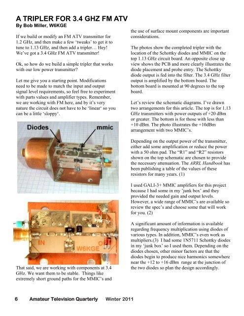
The photos show the completed tripler with the<br />
location of the Schottky diodes and MMIC on the<br />
top 1.13 GHz circuit board. An opposite close up<br />
view shows the PCB and more clearly illustrates the<br />
diode placement and probe entry. The Schottky<br />
diode output is fed into the filter. The 3.4 GHz filter<br />
output is amplified by the bottom board. The<br />
bottom board is mounted at 90 degrees to the top<br />
board.<br />
Let’s review the schematic diagrams. I’ve drawn<br />
two arrangements for this article. The top is for 1.13<br />
GHz transmitters with power outputs of +20 dBm<br />
or greater. The bottom is for those with less than<br />
+10 dBm. The photo illustrates the +10dBm<br />
arrangement with two MMIC’s.<br />
Depending on the output power of the transmitter,<br />
either add some amplification or reduce the power<br />
with a 50 ohm pad. The “R1” and “R2” resistors<br />
shown on the top schematic are chosen to provide<br />
the necessary attenuation. The ARRL Handbook has<br />
been publishing a table of the values of these<br />
resistors for many years. (1)<br />
I used GALI-3+ MMIC amplifiers for this project<br />
because I had some in my ’junk box’ and they<br />
provided the needed gain and output levels.<br />
However, a wide range of MMIC’s are available so<br />
review the spec’s and choose some that will work<br />
for you. (2)<br />
That said, we are working with components at 3.4<br />
GHz. We want them to be stable. Things like<br />
extremely short ground paths for the MMIC’s and<br />
A significant amount of information is available<br />
regarding frequency multiplication using diodes of<br />
various types. In addition, MMIC’s even work as<br />
multipliers.(3) I had some 1N5711 Schottky diodes<br />
in my ‘junk box’ so I used them. Depending on the<br />
diodes chosen, other minor factors are that the<br />
diodes begin to produce nice harmonics somewhere<br />
near the +12 to +16 dBm range at the junction of<br />
the two diodes so plan the design accordingly.<br />
6 Amateur Television Quarterly <strong>Winter</strong> <strong>2011</strong>