
You also want an ePaper? Increase the reach of your titles
YUMPU automatically turns print PDFs into web optimized ePapers that Google loves.
Series <strong>CH2</strong>E/<strong>CH2</strong>F/<strong>CH2</strong>G/<strong>CH2</strong>H<br />
Auto Switch Precautions 2<br />
Be sure to read before handling.<br />
Warning<br />
1. Do not drop or bump.<br />
Do not drop, bump or apply excessive impacts (300m/s² or more<br />
for reed switches and 1000m/s² or more for solid state switches)<br />
while handling. Although the body of the switch may not be damaged,<br />
the inside of the switch could be damaged and cause a malfunction.<br />
2. Do not carry a <strong>cylinder</strong> by the auto switch<br />
lead wires.<br />
Never carry a <strong>cylinder</strong> by its lead wires. This may not only cause<br />
broken lead wires, but it may cause internal elements of the switch<br />
to be damaged by the stress.<br />
3. Mount switches using the proper fastening<br />
torque.<br />
When a switch is tightened beyond the range of fastening torque,<br />
the mounting screws, mounting bracket or switch may be damaged.<br />
On the other hand, tightening below the range of fastening<br />
torque may allow the switch to slip out of position. (Refer to the<br />
switch mounting procedure for each series regarding switch<br />
mounting, movement and tightening torque, etc.)<br />
4. Mount a switch at the center of the operating<br />
range.<br />
Adjust the mounting position of an auto switch so that the piston<br />
stops at the center of the operating range (the range in which a<br />
switch is ON).<br />
(The mounting positions shown in the catalog indicate the optimum<br />
position at the stroke end.) If mounted at the end of the operating<br />
range (around the borderline of ON and OFF), operation will<br />
be unstable.<br />
Warning<br />
Mounting and Adjustment<br />
Wiring<br />
1. Avoid repeatedly bending or stretching lead<br />
wires.<br />
Broken lead wires will result from repeatedly applying bending<br />
stress or stretching force to the lead wires.<br />
2. Be sure to connect the load before power is<br />
applied.<br />
<br />
If the power is turned ON when an auto switch is not connected to<br />
a load, the switch will be instantly damaged because of excess<br />
current.<br />
3. Confirm proper insulation of wiring.<br />
Be certain that there is no faulty wiring insulation (contact with<br />
other circuits, ground fault, improper insulation between terminals,<br />
etc.). Damage may occur due to excess current flow into a switch.<br />
4. Do not wire with power lines or high voltage<br />
lines.<br />
Wire separately from power lines or high voltage lines, avoiding<br />
parallel wiring or wiring in the same conduit with these lines.<br />
Control circuits containing auto switches may malfunction due to<br />
noise from these other lines.<br />
Warning<br />
5. Do not allow short circuit of loads.<br />
<br />
If the power is turned ON with a load in a short circuited condition,<br />
the switch will be instantly damaged because of excess current<br />
flow into the switch.<br />
<br />
J51 and all models of PNP output type switches do not have builtin<br />
short circuit protection circuits. If loads are short circuited, the<br />
switches will be instantly damaged, as in the case of reed switches.<br />
∗ Take special care to avoid reverse wiring with the brown (red)<br />
power supply line and the black (white) output line on 3 wire type<br />
switches.<br />
6. Avoid incorrect wiring.<br />
<br />
∗ A 24VDC switch with indicator light has polarity. The brown (red)<br />
lead wire or terminal No.1 is (+), and the blue (black) lead wire or<br />
terminal No.2 is (–).<br />
1) If connections are reversed, a switch will operate, however, the<br />
light emitting diode will not light up.<br />
Also note that a current greater than that specified will damage a<br />
light emitting diode and it will no longer operate.<br />
Applicable models:D-A33, A34, A44,<br />
D-A53, A54, B53, B54<br />
2) Note however, that in the case of 2 color indicator type auto<br />
switches (A59W, B59W), if the wiring is reversed, the switch will<br />
be in a normally ON condition.<br />
<br />
1) If connections are reversed on a 2 wire type switch, the switch will<br />
not be damaged if protected by a protection circuit, but the switch<br />
will be in a normally ON state. However, it is still necessary to<br />
avoid reversed connections, since the switch could be damaged<br />
by a load short circuit in this condition.<br />
∗2) If connections are reversed (power supply line + and power supply<br />
line –) on a 3 wire type switch, the switch will be protected by<br />
a protection circuit. However, if the power supply line (+) is connected<br />
to the blue (black) wire and the power supply line (–) is<br />
connected to the black (white) wire, the switch will be damaged.<br />
2 wire<br />
Output (+)<br />
Output (–)<br />
Power supply<br />
GND<br />
Output<br />
Diagnostic output<br />
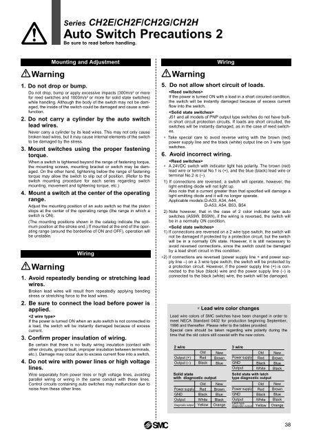
∗ Lead wire color changes<br />
Old<br />
Red<br />
Black<br />
Solid state<br />
with diagnostic output<br />
Old<br />
Red<br />
Black<br />
White<br />
Yellow<br />
Wiring<br />
Lead wire colors of <strong>SMC</strong> switches have been changed in order to<br />
meet NECA Standard 0402 for production beginning September,<br />
1996 and thereafter. Please refer to the tables provided.<br />
Special care should be taken regarding wire polarity during the<br />
time that the old colors still coexist with the new colors.<br />
New<br />
Brown<br />
Blue<br />
New<br />
Brown<br />
Blue<br />
Black<br />
Orange<br />
3 wire<br />
Power supply<br />
GND<br />
Output<br />
Power supply<br />
GND<br />
Output<br />
Latch type<br />
diagnostic output<br />
Old<br />
Red<br />
Black<br />
White<br />
Solid state with latch<br />
type diagnostic output<br />
Old<br />
Red<br />
Black<br />
White<br />
Yellow<br />
New<br />
Brown<br />
Blue<br />
Black<br />
New<br />
Brown<br />
Blue<br />
Black<br />
Orange<br />
38