High Volume Air Sampler Operating Instructions - Sargent Welch
High Volume Air Sampler Operating Instructions - Sargent Welch
High Volume Air Sampler Operating Instructions - Sargent Welch

You also want an ePaper? Increase the reach of your titles
YUMPU automatically turns print PDFs into web optimized ePapers that Google loves.
<strong>High</strong> <strong>Volume</strong> <strong>Air</strong> <strong>Sampler</strong> #15000<br />
Purpose:<br />
OPERATING INSTRUCTIONS<br />
Device to acquire samples of airborne particulates. Once the particulates have been acquired<br />
a variety of chemical tests can be performed to analyze the nature of the pollutants.<br />
Contents:<br />
One (1) <strong>High</strong> <strong>Volume</strong> <strong>Air</strong> <strong>Sampler</strong><br />
One (1) Manometer<br />
Twenty F i v e (25) Filter disks (8-12 m)<br />
One (1) Thermometer<br />
Required Accessories:<br />
Desiccator<br />
Analytical balance (1 mg accuracy)<br />
CAUTION<br />
Running the air sampler with a clogged filter may cause the unit to overheat. Reduce run times<br />
if exhaust temperature exceeds 170 F (76 C).<br />
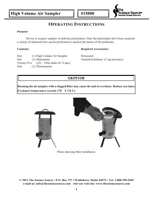
Photo showing filter installation.<br />
© 2011 The Science Source • P.O. Box 727 • Waldoboro, Maine 04572 • Tel. 1-800-299-5469<br />
e-mail us: info@thesciencesource.com visit our web site: www.thesciencesource.com<br />
1
CAUTION<br />
Running the air sampler with a clogged filter may cause the unit to overheat. Reduce run<br />
times if exhaust temperature exceeds 170 F (76 C).<br />
Typically a sample collection run will be between two to four hours. However, in dusty or heavily<br />
polluted areas the sampler must not be left unattended. <strong>High</strong> concentrations of particulate matter<br />
will saturate the collection filter and restrict air flow through the air sampler. The restricted air<br />
flow will cause the air sampler to overheat. The air sampler must not operate at temperatures<br />
above 170 degrees Fahrenheit (76 degrees Celsius). If the air sampler operates at temperatures<br />
above 170 degrees Fahrenheit, plastic deformation of the sampler housing will occur and the<br />
sampler will be damaged beyond repair.<br />
In dusty or heavily polluted environments the <strong>Air</strong> <strong>Sampler</strong> must be monitored for filter saturation<br />
and overheating. A thermometer is provided for exhaust air temperature monitoring. Periodically,<br />
(every 15-30 minutes) the sampler exhaust air temperature should be checked by holding the<br />
thermometer in the exhaust air stream for 30 seconds to collect temperature measurements. If the<br />
exhaust temperature exceeds 170 degrees Fahrenheit (76 degrees Celsius) the <strong>Air</strong> <strong>Sampler</strong> must be<br />
switched off and allowed to cool. The filter must be changed prior to operating the <strong>Air</strong> <strong>Sampler</strong> on<br />
another trial. Do not run the sampler without a filter installed while the manometer is attached and<br />
filled. The much greater flow of unrestricted air is beyond the range the manometer is designed to<br />
measure, and may eject water from the manometer slant tube.<br />
Experiment #1:<br />
<strong>High</strong> <strong>Volume</strong> Particle Sampling Indoors<br />
One of the major indices of air pollution is the quantity<br />
of particulate matter in each cubic meter of air in the<br />
environment. A standard technique for determining the<br />
mass of particulate material in the atmosphere is to<br />
draw the air through a preweighed high efficiency<br />
(small pore size) filter at a known volumetric flow<br />
rate. The filter collects all the particulate matter in the<br />
air which passes through it. It may then be reweighed<br />
to determine its net gain. The Public Health Services,<br />
both state and federal, use this technique as the<br />
accepted standard for particulate concentration<br />
determination. This experiment uses a high pressure<br />
blower to draw particulate laden air through a filter. It<br />
does not depend on the settling out of particles and<br />
therefore samples a greater fraction of matter. It is also<br />
very accurate but only for a mass determination.<br />
Particle count and size determinations are not<br />
practical.<br />
Materials Required:<br />
<strong>High</strong> volume air sampler<br />
Filter disks<br />
Balance capable of weighing 1 milligram<br />
Experimental Procedure:<br />
Using a pencil, write a sample number on the backside<br />
of a filter disk and desiccate it for several hours. When<br />
the filter has been desiccated, weigh it on an analytical<br />
balance to the nearest milligram. Record the sample<br />
number and weight.<br />
Swivel the weather cap to one side and place a filter on<br />
the supporting screen on the top of the sampler. Hold<br />
the filter in place with the white filter cover. This also<br />
forces all of the air to pass through the filter. Return<br />
the weather cap to its vertical position. Place the<br />
sampler in a corner of the classroom or in the hall near<br />
an electrical outlet. Turn the sampler on and allow it to<br />
run for two to four hours. Be sure to check the sampler<br />
temperature at regular 20 minute intervals. Record the<br />
initial and final flow rates. This can be done by<br />
reading the pressure differential on the manometer or<br />
by allowing the sampler to inflate a large plastic bag of<br />
known volume and recording the time required to do<br />
this. To obtain the final flow rate, repeat this step just<br />
before the unit is to be turned off. Use the average of<br />
© 2011 The Science Source • P.O. Box 727 • Waldoboro, Maine 04572 • Tel. 1-800-299-5469<br />
e-mail us: info@thesciencesource.com visit our web site: www.thesciencesource.com<br />
2
these two flow rates in your calculations.<br />
After sampling for a two to four hour period, carefully<br />
remove the filter paper and place it in a desiccator for<br />
several hours to remove any moisture. When the filter<br />
has been desiccated, weigh it again to determine the<br />
net gain of collected particulate material. Express your<br />
results in micrograms of material collected per cubic<br />
meter of air sampled.<br />
If possible have some students operate the air sampler<br />
during inactive hours such as Saturday, Sunday, or<br />
before/after school when there is very little activity.<br />
Compare this data with the data accumulated from the<br />
filter paper which was placed in an area of activity.<br />
Sample Calculation:<br />
A desiccated filter had an initial weight of 3.300<br />
grams. After sampling in the <strong>High</strong> <strong>Volume</strong> <strong>Air</strong><br />
<strong>Sampler</strong> for 4 hours, it was desiccated and reweighed.<br />
The final weight was 3.600 grams. The initial flow rate<br />
was 700 liters per minute and the final flow rate was<br />
600 liters per minute. Calculate the concentration of<br />
particulate matter in the sampled atmosphere in<br />
3<br />
micrograms per cubic meter ( g/m ). (We will make<br />
6<br />
use of the conversion factor 10 g/g in the<br />
concentration calculation).<br />
Net Gain (particulate mass):<br />
Final filter weight (grams) 3.600g<br />
- Initial filter weight (grams) -3.300g<br />
Net Gain (grams) 0.300g<br />
Average Flow Rate (through filter):<br />
Final flow rate / 2 (liters/min) 300.0 l/min<br />
+ Initial flow rate / 2 (liters/min) 350.0 l/min<br />
Average flow rate (liters/min) 650.0 l/min<br />
Particulate Concentration:<br />
(Net Mass Gain)/(Ave Flow Rate•Sampling Time)<br />
-6<br />
0.300g/(650 l/min • 240 min) = 1.923 x 10 g/l<br />
Convert to the Requested Units:<br />
-6 6 3 3<br />
1.923 x 10 g/liter • 10 g/g • 10 liter/m<br />
3 3<br />
Particulate concentration = 1.923 x 10 g/m<br />
Experiment #2: Indoor sampling vs Outdoor<br />
sampling<br />
The assessment of exposure of population groups<br />
to air contaminants must be based upon an appraisal of<br />
all environments in which that exposure occurs. The<br />
indoor environment is of considerable importance,<br />
since metropolitan populace spends far more time<br />
indoors than out. In northern latitudes during the<br />
winter (heating) season, the proportion of time spent<br />
indoors is maximized. It is also during the winter<br />
season that air contamination is most severe. This<br />
experiment will demonstrate the degree of protection<br />
from pollution which a building affords the people<br />
inside.<br />
Materials Required:<br />
(This experiment can be run with one sampler, but<br />
two samplers will make the testing more accurate)<br />
<strong>High</strong> <strong>Volume</strong> <strong>Air</strong> <strong>Sampler</strong><br />
Filter disks<br />
Balance capable of weighing 1 mg.<br />
Procedure:<br />
Operate the sampler for 1 hour in the class room<br />
as explained in Experiment #1. Remove the filter paper<br />
and put it in a desiccator. Put a second piece of<br />
desiccated filter paper into the sampler. Place the<br />
sampler just outside the window of the room and<br />
sample for 1 hour. Repeat this testing procedure<br />
several times to obtain a good statistical analysis.<br />
Perform this testing for at least a week. Which papers<br />
show the highest contaminant concentrations?<br />
If two samplers are available, they should be<br />
operated simultaneously; one inside the class and the<br />
other outside the window. Make your calculations as<br />
explained in experiment #1. Can you correlate the<br />
degree of pollution with any activity such as rush hour<br />
traffic?<br />
Experiment #3: <strong>Air</strong> Pollution Analysis<br />
(This experiment has been reproduced from "The<br />
chemical Analysis of <strong>Air</strong> Pollutants" by Morris Jacobs,<br />
Ph.D. through the courtesy of John Wiley & Sons,<br />
New York and is suitable for advanced senior high<br />
school or college level courses).<br />
Introduction:<br />
Many times it is very important to determine not<br />
only the total mass of particulate material in the<br />
atmosphere, but also what and how much of each<br />
component is in the air. This section gives techniques<br />
© 2011 The Science Source • P.O. Box 727 • Waldoboro, Maine 04572 • Tel. 1-800-299-5469<br />
e-mail us: info@thesciencesource.com visit our web site: www.thesciencesource.com<br />
3
and details for analyzing quantitatively what is in the<br />
air we breath. The following procedures can be quite<br />
involved and difficult to perform due to the extremely<br />
small sample sizes. Therefore, the following material<br />
is provided to illustrate the various techniques used to<br />
analyze unknown materials. If you are fortunate<br />
enough to have access to chemical laboratory facilities,<br />
you may wish to try them your self.<br />
Materials Required:<br />
Carbon dioxide gas<br />
Sodium sulfate, anhydrous<br />
Graduated cylinder, 100 ml<br />
Several 250 ml flasks<br />
Analytical balance<br />
Sodium hydroxide, solid<br />
Hydrochloric acid<br />
Several small tared (weighed) flasks<br />
Chloroform or ether alcohol<br />
Fritted glass funnel, medium porosity, weighed<br />
Hot plate<br />
Two Separatory funnels<br />
Procedure:<br />
1) Sample the air for at least 4 hours as described in<br />
Experiment #1.<br />
2) Cut the sample into 12 equal pie shaped pieces<br />
(every 30 degrees).<br />
3) The wedges, each of which represents 8.33<br />
percent of the original sample, are used as<br />
follows: Extract two wedges and use for the<br />
determination of sulfates, nitrates, and pH. Use<br />
two wedges for the determination of fluorides and<br />
hold two wedges in reserve. These portions may<br />
be used for other analyses if desired.<br />
Determination of Water Soluble Particulate<br />
Matter:<br />
A preliminary separation into insoluble, water<br />
soluble, and ether soluble fractions is made. Weigh the<br />
sample in a small tared flask. Loosen the sample by the<br />
addition of a small amount of chloroform or ether<br />
alcohol. Add 100 ml of ethyl ether to the flask and<br />
rotate to assist in the solution of the specimen. Filter<br />
the test solution through a weighed medium porosity<br />
fritted-glass funnel. Repeat the ether treatment. Wash<br />
the residue in the flask with 25 ml of water and filter<br />
through the same fritted funnel. Repeat the water<br />
washing procedure. Dry the flask and funnel then<br />
weigh to determine the amount of insoluble material.<br />
Transfer the ether-water mixture to a separatory<br />
funnel. Rinse the container with small amounts of<br />
ether and water adding these rinsings to the separatory<br />
funnel. Shake fairly vigorously, then allow to stand<br />
until the two layers separate. Draw off the water layer<br />
into a clean flask. Add 100 ml of water to the<br />
separatory funnel. Shake fairly vigorously and again<br />
allow the layers to separate. Draw off the water layer<br />
into the same flask used for the first extract.<br />
Transfer the combined water extracts to another<br />
separatory funnel and extract with 50 ml of ether.<br />
Draw off the water layer and evaporate to a small<br />
volume in a hot plate. Transfer the solution to a small<br />
weighed flask and evaporate to dryness. Weigh this as<br />
the water-soluble fraction.<br />
Combine the ether solution remaining in the<br />
preceding operation with that reserved above and use<br />
this ether solution for isolation of the basic groups.<br />
Isolation of Basic Groups:<br />
Combine the ether extracts in one separatory<br />
funnel and add 60 ml of 1 N hydrochloric acid. Shake<br />
fairly vigorously then allow to stand until the two<br />
layers have separated completely. Draw off the lower<br />
layer into a clean flask and repeat the acid extraction<br />
using 60 ml of 1 N hydrochloric acid. Add the second<br />
acid layer to the first. Wash the ether solution in the<br />
separatory funnel with a small amount of water<br />
without shaking. Add the wash water to the acid<br />
extracts. Transfer the acid extract to another separatory<br />
funnel and extract with 25 ml of ether. Draw off the<br />
acid solution into a flask. Add the ether to the other<br />
extracts remaining in the separatory funnel and save<br />
for the isolation of acid groups. Add the ether to the<br />
other extracts remaining in the separatory funnel and<br />
save for the isolation of acid groups.<br />
Add solid sodium hydroxide cautiously to the acid<br />
extract until the solution is alkaline. Transfer to a<br />
separatory funnel and extract twice with 80 ml<br />
portions of ether. Discard the acid layer after the<br />
second extraction. Wash the combined ether extracts<br />
with a small volume of water with gentle shaking.<br />
Discard the wash water.<br />
Transfer the ether solution to a dry flask<br />
containing 10 to 15 grams of anhydrous sodium<br />
sulfate. Rotate gently to mix, stopper carefully, and<br />
allow to stand several hours or overnight. Filter the<br />
dried ether solution through a small filter paper of<br />
fritter glass funnel into a dry flask. Be sure to wash the<br />
original flask, containing the sodium sulfate with<br />
© 2011 The Science Source • P.O. Box 727 • Waldoboro, Maine 04572 • Tel. 1-800-299-5469<br />
e-mail us: info@thesciencesource.com visit our web site: www.thesciencesource.com<br />
4
several portions of anhydrous ether adding these<br />
washings to the other ether solution. Carefully<br />
evaporate in a hood to a small volume. Transfer the<br />
solution to a tared weighing bottle or test tube rinsing<br />
the flask with small amounts of ether. Evaporate to<br />
constant weight spontaneously or at a temperature<br />
below the boiling point of ether. This is the basic or<br />
amine fraction.<br />
Isolation of Acid Groups: All Acids<br />
Extract the combined ether from the basic group<br />
separation twice with 60 ml portions of 5 per cent<br />
sodium hydroxide solution and place the extracts in a<br />
separatory funnel. Wash the ether layer with a small<br />
volume of water and add the water to the alkaline<br />
extracts. Extract the combined alkaline solutions with<br />
25 ml of ether and add this extract to the ether<br />
remaining above. Reserve for isolation of neutral<br />
groups.<br />
Acidify the alkaline solution with concentrated<br />
hydrochloric acid to pH 1 to 2. Extract twice with 60<br />
ml of ether. Combine the ether extracts. place in<br />
another separatory funnel, and wash with a small<br />
volume of water. Discard the water layer. Transfer this<br />
ether layer to a flask containing 10 to 15 grams of<br />
anhydrous sodium sulfate, agitate gently, stopper, and<br />
allow to stand for several hours or overnight. Filter the<br />
solution into a dry flask and wash the flask containing<br />
the anhydrous sodium sulfate and filter several times<br />
with anhydrous ether catching the washings in the<br />
flask containing the filtrate. Carefully evaporate to a<br />
small volume, transfer to a tared weighing bottle or<br />
test tube, and evaporate to constant weight. The<br />
residue is the acid fraction.<br />
Isolation of Acid Groups: Weak Acids and Strong<br />
Acids<br />
Repeat the above procedure for the isolation of all<br />
acids. Bubble carbon dioxide through the alkaline<br />
solution obtained until a pH of 8 is produced.<br />
Extract this solution twice with 60 ml of ether.<br />
Combine the ether extracts, place in another separatory<br />
funnel, and wash with a small volume of water. Add<br />
the water to the previously extracted slightly alkaline<br />
solution. Dry the ether layer with anhydrous sodium<br />
sulfate as detailed. Filter the dried ether layer into a<br />
flask, and wash the flask containing the sodium sulfate<br />
as detailed. Filter the dried ether layer into a flask, and<br />
wash the flask containing the sodium sulfate and the<br />
filter several times with anhydrous ether. Carefully<br />
evaporate to a small volume, transfer to a tared<br />
weighing bottle or test tube, wash the flask with small<br />
portions of anhydrous ether, and evaporate to constant<br />
weight. This gives the weak acid fraction.<br />
Acidify the weakly alkaline solution with<br />
hydrochloric acid to a pH of 1 to 2. Extract twice with<br />
60 ml of ether. Combine the ether extracts, place in<br />
another separatory funnel, and wash with a small<br />
volume of water. Discard the water layer. Transfer the<br />
ether layer to a flask containing 10 to 15 grams of<br />
anhydrous sodium sulfate, shake gently, stopper, and<br />
allow to stand overnight. Filter the dried ether solution<br />
into a dry flask and wash the flask containing the<br />
sodium sulfate and the filter with several portions of<br />
anhydrous ether. Carefully evaporate to a small<br />
volume, transfer to a tared weighing bottle and<br />
evaporate to constant weight. This gives the strong<br />
acid fraction.<br />
Isolation of Neutral Groups:<br />
Transfer the ether solution reserved for the<br />
isolation of the neutral group to a flask containing<br />
several grams of anhydrous sodium sulfate, shake<br />
gently, stopper, and allow to stand several hours or<br />
overnight. Filter through a fritted filter into a clean<br />
flask. Wash original flask and funnel with several<br />
portions of anhydrous ether and catch the washings in<br />
the same flask. Carefully evaporate the ether solution<br />
to a small volume then transfer to a tared weighing<br />
bottle or test tube. Evaporate to a constant weight. The<br />
residue is the neutral fraction.<br />
Experiment #3: Detection and Measurement of<br />
Radioactive Particulate Matter in the Atmosphere<br />
As the rate of radioactive material usage increases<br />
it is inevitable that an increase in the ambient<br />
radioactivity level of the atmosphere will be noted. It<br />
is extremely important that the levels be monitored to<br />
enable scientists to make predictions relative to the<br />
future of mankind with respect to radioactive<br />
increases. This experiment deals with the measurement<br />
of radioactive particulate matter in the atmosphere.<br />
© 2011 The Science Source • P.O. Box 727 • Waldoboro, Maine 04572 • Tel. 1-800-299-5469<br />
e-mail us: info@thesciencesource.com visit our web site: www.thesciencesource.com<br />
5
degrees Celsius or go below a flow rate of 400<br />
liters/minute. If this operating temperature is<br />
exceeded, permanent damage to the sampler housing<br />
may result . Remember, as the filter collects particles,<br />
the flow rate will decrease. Therefore, if the filter<br />
becomes excessively clogged, the flow rate will drop<br />
and the sampler may overheat. Do not leave the<br />
sampler unattended.<br />
The sampler may be cleaned with mild soap and<br />
water. Do not allow water to enter the sampler. Do not<br />
use solvents (alcohol, acetone, paint thinner, etc.) to<br />
clean the air sampler. Keep the filter support screen<br />
clean and dry at all times.<br />
Figure 4<br />
Placement of filter paper and Geiger Tube to test for<br />
radioactivity.<br />
Materials Required:<br />
<strong>High</strong> <strong>Volume</strong> <strong>Air</strong> <strong>Sampler</strong><br />
Filter disks<br />
Geiger counter<br />
Procedure:<br />
Cut a small piece of filter paper approximately 5<br />
cm by 5 cm square and place it in a radioactivity<br />
counter to get a background count on radioactive<br />
particles on the paper (Figure 1).<br />
Place a filter disk in the air sampler and replace<br />
the weather cap. Place the sampler outside and let run<br />
for four hours. Record the initial and final air flow<br />
rates. Remove the filter paper from the sampler and cut<br />
a 5 x 5 cm square from the middle of the filter paper.<br />
Insert this square into the counter to determine the<br />
level of radioactivity as compared to the background<br />
count made previously. The same filter should be<br />
measured for radioactivity again in 24 hours. This will<br />
allow Thorium B (half life = 10.6 hours) and the<br />
Radon daughters which have a much shorter halflife to<br />
decay completely.<br />
Use and Care of the <strong>High</strong> <strong>Volume</strong> <strong>Air</strong> <strong>Sampler</strong>.<br />
Use caution when using filters other than those<br />
supplied with the instrument. If the filter pore size is<br />
too small the air flow through the sampler will be<br />
restricted and result in overheating.<br />
This air sampler is designed for normal operation<br />
in the 50 to 76 degree Celsius range. The temperature<br />
of the air exiting the sampler should not exceed 76<br />
The supplied filters provide an average flow rate<br />
of ~700 l/minute when clear. The slant tube<br />
manometer supplied with the sampler has been<br />
designed to measure flows up to ~1000 l/min. Use<br />
caution when substituting filters, as filters that are too<br />
fine may restrict the air flow and result in overheating.<br />
More porous filters will cause the manometer to rise<br />
above its designed capacity and may cause spillage.<br />
The instrument must be recalibrated if filters outside<br />
of the manometer’s design range are used.<br />
To calibrate the air sampler, first disconnect the<br />
manometer tubing from the aluminum ports. Attach a<br />
large plastic bag of known volume (the volume can be<br />
calculated) to the exit port of the air sampler (a rubber<br />
band works nicely). Place a clean filter on the filter<br />
support screen and secure in place with the filter cover.<br />
Turn the sampler on and record the time required to<br />
fill the bag. Dividing the volume of the bag by the time<br />
required to fill the bag. This is the flow rate of the<br />
sampler in liters/second. This procedure should be<br />
done at the beginning and end of each experiment.<br />
The electrical load of the running sampler should<br />
be less than 1000 watts. Use appropriately rated<br />
extension cords if necessary to reach the test location.<br />
Flow rate calibration activities should be conducted<br />
under the actual test conditions.<br />
Time Allocation:<br />
To prepare this product for an experimental trial<br />
should take less than ten minutes. Actual experiments<br />
will vary with needs of students and the method of<br />
instruction, but are easily concluded within one class<br />
period.<br />
Feedback:<br />
If you have a question, a comment, or a suggestion that<br />
would improve this product, you may call our toll free<br />
number 1-800-299-5469, or e-mail us:<br />
info@thesciencesource.com. Our fax number is: 1-<br />
207-832-7281.<br />
© 2011 The Science Source • P.O. Box 727 • Waldoboro, Maine 04572 • Tel. 1-800-299-5469<br />
e-mail us: info@thesciencesource.com visit our web site: www.thesciencesource.com<br />
6
Appendix: Using the 15005 Manometer<br />
Manometer Contents:<br />
One graduated slant tube manometer block<br />
One 2 ft length of manometer tubing<br />
One syringe<br />
One stopper<br />
Recommended additional materials:<br />
Celsius thermometer<br />
Local weather data<br />
The manometer supplied with the <strong>Air</strong> <strong>Sampler</strong> is a handy tool that can be used to calculate volumetric airflow during a<br />
particle sampling experiment. Approximate air flow values are provided in the 15000 <strong>Air</strong> <strong>Sampler</strong> instructions but<br />
more accurate calculations can be derived using the height of a water column displaced by the difference between<br />
static pressure and total pressure of air in the exhaust port.<br />
Procedure:<br />
Affix the manometer block to the air sampler housing by mounting its aluminum plate to the left threaded stud of the<br />
weather cap, as viewed from the exhaust side. Using the syringe, inject approx. 20ml into the manometer cylinder<br />
through the stopper hole. The meniscus should be at the indicating mark on the backing plate. Replace the stopper.<br />
The manometer is level when this meniscus is at its line and the meniscus in the slant tube is at the beginning of the<br />
scale. Adjust the angle of the manometer block and/or the volume of water added until this is achieved. The water<br />
column in the slant tube should be “reset” during adjustment by gently blowing into the slant-tube hose until air<br />
bubbles up in the chamber and then allowing the water to again find its level. The column itself should always be free<br />
of air bubbles. Dislodge any water droplets clinging inside the air tubes. Attach the manometer tubing emerging from<br />
top of the manometer cylinder (high pressure) to the aluminum port on top of the air sampler exhaust. Attach the low<br />
pressure tube to the port beneath the exhaust pipe. Make sure a clean filter is installed in the air sampler.<br />
The upper aluminum fitting can be seen to be directed into the flow of the exhaust port. This produces a region of<br />
pressure above the column of water in the manometer cylinder that is equal to the total pressure of air within the<br />
exhaust pipe, P tot . This total pressure consists of the pressure of the moving or dynamic air, P dyn , and the static<br />
pressure of the air in the system, P :<br />
stat<br />
P tot = P dyn + Pstat<br />
The region above the water of the slant tube is at P stat, as it is connected to the lower aluminum fitting which is<br />
perpendicular to the air flow. The difference in P tot and P stat results in movement of the column of water upward until<br />
that movement equals the hydrostatic pressure of the column. The height of the water column therefore represents<br />
P .<br />
dyn<br />
The manometer’s slant tube is set at 4 degrees from horizontal. Note that its scale measures the extension of water<br />
along the hypotenuse, not vertical displacement. Hence,<br />
where:<br />
P dyn =ghg(d sin)<br />
3<br />
= density of fluid (water), kg/m = 1000<br />
2<br />
g = acceleration due to gravity, m/s = 9.8<br />
h = height of fluid column, m<br />
d = extension along the slant scale, m<br />
= angle of slant tube<br />
This gives us P dyn in Pascals. From Bernoulli, we know that the dynamic pressure of a fluid is related to its velocity.<br />
We can apply the P we just calculated to his equation:<br />
dyn<br />
P dyn = 1/ 2 v 2<br />
© 2011 The Science Source • P.O. Box 727 • Waldoboro, Maine 04572 • Tel. 1-800-299-5469<br />
e-mail us: info@thesciencesource.com visit our web site: www.thesciencesource.com<br />
7
where:<br />
Rearranging,<br />
3<br />
= density of fluid (air), kg/m (see below)<br />
v = velocity of fluid (m/s)<br />
v = (2 P dyn / ) 0.5<br />
We now have a measure of the velocity of air in the exhaust pipe. Multiplying this by the cross-sectional area of the<br />
pipe gives us flow:<br />
where:<br />
2<br />
F = v(r )<br />
3<br />
F = flow, m /s<br />
r = radius of exhaust pipe, m = 0.026<br />
Flow can finally be converted into whatever units are preferred and then divided by distance traveled on the slant<br />
scale for quick reference in future trials.<br />
Upon startup of the air sampler, the manometer will require several minutes to equilibrate to its full height. Similarly,<br />
the column recedes very slowly when pressure is removed or is diminished. For best results, when measuring a lower<br />
flow following a higher one, such as at the end of a sampling run where flow is diminished due to particulate in the<br />
filter, “reset” the water column as described above and take a final reading.<br />
Correcting for air density:<br />
Greater accuracy in flow measurement can be achieved by taking additional steps in calculating v from P dyn. It can be<br />
seen that this determination is sensitive to air density, which is in turn affected by temperature, local atmospheric<br />
pressure, and humidity.<br />
Temperature correction is highly recommended. The air sampler’s motor generates heat, and affects the temperature<br />
of the air it pushes. Therefore, the density of the exhausted air changes significantly from resting to operational<br />
values. If possible, the exhaust temperature should be measured with a thermometer. Dry air density can then be<br />
approximated by the ideal gas law:<br />
= P / (R d*T)<br />
Where:<br />
= density of fluid (air), kg/m 3<br />
P = air pressure (standard), Pa = 101325<br />
R d = gas constant of dry air, J/(kg*K) = 287.05<br />
T = temperature (exhausted air), K<br />
Further correction for local atmospheric pressure and humidity is less important, but these values may easily be<br />
obtained from weather websites. Using these, a very accurate value for air density is calculable using the ideal gas<br />
law and a function for the partial pressure of water vapor:<br />
= [P d / (R d*T)] + [P v / (R v*T)]<br />
Where:<br />
P d = pressure of dry air (standard), Pa = 101325<br />
P v = pressure of water vapor in air, Pa<br />
R = gas constant of water vapor, J/(kg*K) = 461.50<br />
v<br />
The partial pressure of water vapor (in Pa) may be estimated by local dewpoint (T<br />
[(7.5* dp)/(237.3+ dp)]<br />
P = 610.78 * 10 T T<br />
v<br />
© 2011 The Science Source • P.O. Box 727 • Waldoboro, Maine 04572 • Tel. 1-800-299-5469<br />
e-mail us: info@thesciencesource.com visit our web site: www.thesciencesource.com<br />
8<br />
dp<br />
, C) by the function:
Since local pressure is the sum of all partial pressures, partial pressure of dry air (P d) is simply difference between<br />
local pressure (in Pa, from weather data) and what we have calculated for P :<br />
P d = P loc - Pv<br />
v<br />
Sample calculation:<br />
manometer travel: 30 mm (0.030 m)<br />
exhaust temperature: 50C (323K)<br />
local pressure: 1012.4 mb (101240 Pa)<br />
dewpoint: 14C<br />
1. Find P v, the partial pressure of water vapor:<br />
P = 610.78 * 10 = 610.78 * 10 = 1598.5 Pa<br />
v<br />
2. Find P d, the partial pressure of dry air:<br />
[(7.5* Tdp)/(237.3+ Tdp)] [(7.5* 14)/(237.3+ 14)]<br />
P d = P loc - P V = 101240 - 1598.5 = 99641.5 Pa<br />
3. Find , air density:<br />
air = [P d / (R d*T)] + [P v / (R v*T)]<br />
= [99641.5 / (287.05*323)] + [1598.5 / (461.50*323)] = 1.085 kg/m 3<br />
4. Find P dyn, dynamic air pressure:<br />
P = ghg(d sin) = 1000*9.8*.030*0.070 = 20.58 Pa<br />
dyn<br />
water<br />
5. Find v, fluid (air) velocity:<br />
6. Find F, flow:<br />
dyn<br />
0.5 0.5<br />
air<br />
v = (2 P / ) = (2*20.58 / 1.085) = 6.159 m/s<br />
2 2<br />
3<br />
F = v(r ) = 6.159 ( 0.026 ) = 0.013 m /s = 780 l/min<br />
© 2011 The Science Source • P.O. Box 727 • Waldoboro, Maine 04572 • Tel. 1-800-299-5469<br />
e-mail us: info@thesciencesource.com visit our web site: www.thesciencesource.com<br />
9