60% reduced - Szathmáry service kft
60% reduced - Szathmáry service kft
60% reduced - Szathmáry service kft

Create successful ePaper yourself
Turn your PDF publications into a flip-book with our unique Google optimized e-Paper software.
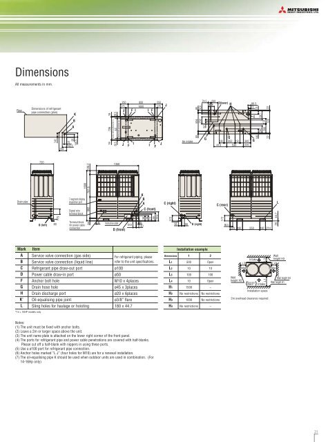
Dimensions<br />
All measurements in mm.<br />
Rear<br />
Dimensions of refrigerant<br />
pipe connection (plan)<br />
141<br />
234<br />
75<br />
142.5<br />
K<br />
B<br />
A<br />
95<br />
140.5<br />
19 726 19<br />
58.5 Anchor bolt positions for F, J<br />
647 58.5<br />
Anchor bolt positions for I<br />
250 850<br />
250<br />
175 1000 175<br />
J F I I F<br />
J<br />
F<br />
I<br />
I<br />
F<br />
J<br />
J<br />
Air intake<br />
74.5<br />
594 85<br />
232 101<br />
57<br />
85<br />
G<br />
232<br />
D(lower)<br />
185 H<br />
G<br />
148 352 158 342<br />
410 530 235<br />
80.5<br />
71<br />
C<br />
G<br />
140 120<br />
240<br />
296.7<br />
295 174<br />
22 720 22<br />
720<br />
126.2<br />
1350<br />
Drain pipe<br />
D (left)<br />
80<br />
175<br />
7-segment display<br />
inspection port<br />
Signal wire<br />
terminal block<br />
Terminal block<br />
for power cable<br />
connection<br />
1690<br />
682 797.8<br />
84<br />
6<br />
K<br />
B<br />
A<br />
C (front)<br />
166<br />
169<br />
211<br />
259<br />
291.6<br />
C (right)<br />
172<br />
Instruction plate<br />
104.9<br />
6<br />
86.1<br />
95<br />
D (front)<br />
90<br />
D (right)<br />
C (rear)<br />
172<br />
86.5<br />
220<br />
180<br />
550<br />
180<br />
214<br />
L<br />
44.7<br />
20<br />
Mark<br />
A<br />
B<br />
C<br />
D<br />
F<br />
G<br />
H<br />
K *<br />
L<br />
Item<br />
Service valve connection (gas side)<br />
Service valve connection (liquid line)<br />
Refrigerant pipe draw-out port<br />
Power cable draw-in port<br />
Anchor bolt hole<br />
Drain hose hole<br />
Drain discharge port<br />
Oil-equalising pipe joint:<br />
Sling holes for haulage or hoisting<br />
For refrigerant piping, please<br />
refer to the unit specifications.<br />
ø100<br />
ø50<br />
M10 x 4places<br />
ø45 x 3places<br />
ø20 x 6places<br />
ø3/8” flare<br />
180 x 44.7<br />
Installation example<br />
Dimensions 1 2<br />
L1 500 Open<br />
L2 10 10<br />
L3 100 100<br />
L4 10 Open<br />
H1 1500 –<br />
H2 No restrictions No restrictions<br />
H3 1000 No restrictions<br />
H4 No restrictions –<br />
Wall<br />
height H2<br />
L2<br />
Intake<br />
Intake<br />
Service<br />
space<br />
L3<br />
L1<br />
Intake<br />
Installation space<br />
2m overhead clearance required<br />
L4<br />
Intake<br />
Wall<br />
height H3<br />
Wall height H4<br />
Wall height H1<br />
*14 + 16HP models only<br />
Notes:<br />
(1) The unit must be fixed with anchor bolts.<br />
(2) Leave a 2m or larger space above the unit.<br />
(3) The unit name plate is attached on the lower right corner of the front panel.<br />
(4) The ports for refrigerant pipe and power cable penetrations are covered with half-blanks.<br />
Please cut off a half-blank with nippers in using these ports.<br />
(5) Use a ø100 port for refrigerant pipe connection.<br />
(6) Anchor holes marked “L J” (four holes for M10) are for a renewal installation.<br />
(7) The oil-equalising pipe K should be used when outdoor units are used in combination. (For<br />
14-16Hp only)<br />
31