Solar controller XTDC - Sorel
Solar controller XTDC - Sorel
Solar controller XTDC - Sorel

Create successful ePaper yourself
Turn your PDF publications into a flip-book with our unique Google optimized e-Paper software.
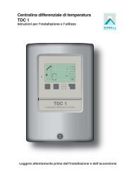
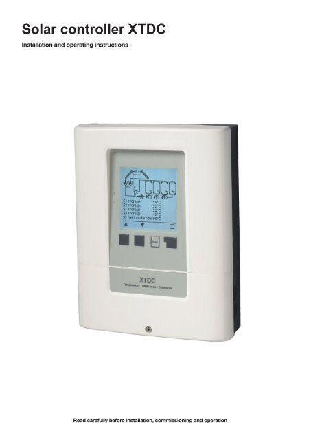
<strong>Solar</strong> <strong>controller</strong> <strong>XTDC</strong><br />
Installation and operating instructions<br />
Read carefully before installation, commissioning and operation
Table of content<br />
A. - Safety instructions 3<br />
A.1. - EC declaration of conformity 3<br />
A.2. - General instructions 3<br />
A.3. - Explanation of symbols 3<br />
A.4. - Changes to the unit 3<br />
A.5. - Warranty and liability 4<br />
A.6. - About the <strong>controller</strong> 4<br />
A.7. - Scope of supply 4<br />
A.8. - Disposal and pollutants 4<br />
B. - Description of <strong>controller</strong> 5<br />
B.1. - Specifi cations 5<br />
B.2. - Temperature resistance table<br />
for Pt1000 sensors 5<br />
C. - Installation 6<br />
C.1. - Wall installation 6<br />
C.2. - Electrical connection 7<br />
C.3. - Installing the temperature sensors 8<br />
C.4. - RC 21 Remote adjuster with thermostat 9<br />
D. - Terminal connection 10<br />
D.1. - Terminal connection 10<br />
D.2. - Terminal connection diagram 10<br />
D.3. - Hydraulic variants / Schemes / Systems 11<br />
E. - Operation 19<br />
E.1. - Display and input 19<br />
E.2 Commissioning help 19<br />
E.3 Free commissioning 20<br />
E.4 Menu sequence and menu structure 20<br />
1. - Measurement values 21<br />
2. - Statistics 21<br />
2.1. - Operating hours 21<br />
2.2. - Heat output 21<br />
2.3. - Graphic overview 21<br />
2.4. - Message log 21<br />
2.5. - Reset/clear 21<br />
3. - Operating modes 22<br />
3.1. - Automatic 22<br />
3.2. - Manual 22<br />
3.3. - Off 22<br />
3.4. - Fill system 22<br />
4. - Settings 23<br />
4.1. - Tmin S (X) 23<br />
4.2. - Tmax S (X) 23<br />
4.3. - Tmax SB 23<br />
4.4. - ∆ T <strong>Solar</strong> S (X) 23<br />
4.5. - Priority S(X) 24<br />
4.6. - T-priority 24<br />
4.7. - Loading time 24<br />
4.8. - Increase 24<br />
5. - Protections / Protective functions 25<br />
5.1. - System protection 25<br />
5.2. - Collector protection 25<br />
5.3. - Recooling 25<br />
5.4. - Frostschutz 26<br />
5.5. - Seizing protection 26<br />
5.6. - Collector alarm 26<br />
6. - Special functions 27<br />
6.1. - Program selection 27<br />
6.2. - Speed control 27<br />
6.2.1. - Variant 27<br />
6.2.2. - Type of pump 27<br />
6.2.3. - Pump menu 28<br />
6.2.3.1. - Pump 28<br />
6.2.3.2. - Output Signal 28<br />
6.2.3.3. - PWM off 28<br />
6.2.3.4. - PWM on 28<br />
6.2.3.5. - PWM Max 28<br />
6.2.3.6. - 0-10V off 28<br />
6.2.3.7. - 0-10V on 28<br />
6.2.3.8. - 0-10V Max 28<br />
6.2.3.9. - Speed when „On“ 28<br />
6.2.3.10. - Show signal 28<br />
6.2.4. - Purging time 29<br />
6.2.5. - Sweep time 29<br />
6.2.6. - max. speed 30<br />
6.2.7. - min. speed 30<br />
6.2.8. - Setpoint 30<br />
6.3. - <strong>Solar</strong> bypass 30<br />
6.3.1. - Variant 30<br />
6.3.2. - Bypass (sensor) 30<br />
6.4. - Thermostat 31<br />
6.4.1. - TH Set 31<br />
6.4.2. - TH hysteresis 31<br />
6.4.3. - Thermostat sensor 1 31<br />
6.4.4. - Thermostat sensor 2 31<br />
6.4.5. - T eco 31<br />
6.4.6. - Storage 31<br />
6.4.7. - Energy saving mode 31<br />
6.4.8. - Periods 31<br />
6.5. - Cooling 32<br />
6.5.1. - Co T set 32<br />
6.5.2. - Co hysteresis 32<br />
6.5.3. - Cooling (sensor) 32<br />
6.5.4. - Periods 32<br />
6.6. - Return fl ow increase 32<br />
6.6.1. - RF Tmax 32<br />
6.6.2. - ∆T return fl ow 32<br />
6.6.3. - Return fl ow (sensor) 32<br />
6.6.4. - Storage (sensor) 32<br />
6.7. - Collector fi eld cooling 33<br />
6.7.1. - Tmax fi eld 33<br />
6.7.2. - Hys min 33<br />
6.7.3. - Hys max 33<br />
6.7.4. - Field cooling sensor 33<br />
6.8. - Anti Legionella 34<br />
6.8.1. - AL T set 34<br />
6.8.2. - AL residence time 34<br />
6.8.3. - Last AL heat 34<br />
6.8.4. - AL sensor 1 34<br />
6.8.5. - AL Sensor 2 34<br />
6.8.6. - AL-times 34<br />
6.9. - Heat transfer 35<br />
6.9.1. - ∆ T Heat transfer 35<br />
6.9.2. - Setpoint 35<br />
6.9.3. - HT Tmin 35<br />
6.9.4. - HT Source (sensor) 35<br />
6.9.5. - HT Drain (Target sensor) 35<br />
6.10. - Difference 36<br />
6.10.1. - ∆ T difference 36<br />
6.10.2. - DF source (sensor) 36<br />
6.10.3. - Diff Tmin 36<br />
6.10.4. - DF Drain (sensor) 36<br />
6.10.5. - DF Tmax 36<br />
6.11. - Solid fuel boiler 37<br />
6.11.1. - SF Tmax 37<br />
6.11.2. - SF Tmin 37<br />
6.11.3. - ∆ T SF 37<br />
6.11.4. - Boiler sensor 37<br />
6.11.5. - Storage sensor 37<br />
6.12. - Error message 37<br />
6.13. - Pressure monitor 38<br />
6.13.1. - Pressure monitor 38<br />
6.13.1.1. - RPS1 / RPS2 38<br />
6.13.1.2. - Pmin 38<br />
6.13.1.3. - Pmax 38<br />
6.14. - Booster pump 38<br />
6.14.1. - Filling time 38<br />
6.15. - Parallel operation R (X) 38<br />
6.15.1. - Delay 38<br />
6.15.2. - Followup time 38<br />
6.16. - Always on 39<br />
6.17. - Heating circuit 39<br />
6.17.1. - Room set day 39<br />
6.17.2. - Room set night 39<br />
6.17.3. - Room sensor 39<br />
6.17.4. - Periods 39<br />
6.18. - Heat quantity 40<br />
6.18.1. - Flow sensor (X) 40<br />
6.18.2. - Return sensor 40<br />
6.18.3. - Anti freeze type 40<br />
6.18.4. - Glycole percentage 40<br />
6.18.5. - Flow rate (X) 40<br />
6.18.6. - Offset ∆ T 40<br />
6.18.7. - VFS (X) 40<br />
6.18.8. - VFS - Position 40<br />
6.18.9. - Reference sensor 40<br />
6.18.10. - Pressure monitor 41<br />
6.18.11. - Pressure monitor 41<br />
6.18.11.1. - RPS1 / RPS2 41<br />
6.18.11.2. - Pmin 41<br />
6.18.11.3. - Pmax 41<br />
6.19. - Sensor calibration 41<br />
6.20. - Commissioning 41<br />
6.21. - Factory settings 41<br />
6.22. - SD-Card 42<br />
6.22.1. - Logging 42<br />
6.22.2. - Free storage 42<br />
6.22.3. - Load confi guration 42<br />
6.22.4. - Save confi guration 42<br />
6.22.5. - Firmware update 42<br />
6.22.6. - Unmount 42<br />
6.23. - Start aid function 42<br />
6.24. - Time and date 42<br />
6.25. - Daylight saving time 42<br />
6.26. - Sleep mode 43<br />
6.27. - Ethernet 43<br />
6.27.1. - Ethernet 43<br />
6.27.2. - MAC Adress 43<br />
6.27.3. - TCP/IP Adress 43<br />
6.27.4. - Network Mask 43<br />
6.27.5. - Gateway 43<br />
6.27.6. - Login 43<br />
6.28. - Temperature unit 43<br />
7. - Menu lock 44<br />
8. - Service values 44<br />
9. - Languages 44<br />
Z.1. Malfunctions with error messages 45<br />
Z.2 Replacing the fuse 46<br />
Z.3 Maintenance 46
A.1. - EC declaration of conformity<br />
Safety instructions<br />
By affixing the CE mark to the unit the manufacturer declares that the <strong>XTDC</strong> conforms to the following relevant safety regulations:<br />
- EC low voltage directive 2006/95/EC<br />
- EC electromagnetic compatibility directive 2004/108/EC<br />
Conformity has been verified and the corresponding documentation and the EC declaration of conformity are kept on file by the manufacturer.<br />
A.2. - General instructions<br />
These installation and operating instructions contain basic instructions and important information regarding safety, installation,<br />
commissioning, maintenance and the optimal use of the unit. Therefore these instructions must be read completely and<br />
understood by the installation technician/specialist and by the system user before installation, commissioning and operation of<br />
the unit.<br />
The valid accident prevention regulations, VDE regulations, the regulations of the local power utility, the applicable DIN-EN<br />
standards and the installation and operating instruction of the additional system components must also be observed. The <strong>controller</strong><br />
does not under any circumstances replace any safety devices to be provided by the customer!<br />
Installation, electrical connection, commissioning and maintenance of the unit may only be carried out by specialists who possess<br />
the appropriate training.<br />
For the user: Make sure that the specialist gives you detailed information on the function and operation of the <strong>controller</strong>. Always<br />
keep these instructions in the vicinity of the <strong>controller</strong>.<br />
A.3. - Explanation of symbols<br />
Danger<br />
Failure to observe these instructions can result in danger to life from electric voltage.<br />
Danger<br />
Failure to observe these instructions can result in serious damage to health such as scalding, or even<br />
life-threatening injuries.<br />
Caution<br />
Failure to observe these instructions can result in destruction of the unit or the system, or damage to the<br />
environment.<br />
Caution<br />
Information which is especially important for the function and optimal use of the unit and the system.<br />
A.4. - Changes to the unit<br />
• Changes, additions to or conversion of the unit are not permitted without the written permission from the manufacturer<br />
• It is likewise forbidden to install additional components that have not been tested together with the unit<br />
• If it becomes clear that safe operation of the unit is no longer possible, for example because of damage to the housing,<br />
then turn the <strong>controller</strong> off immediately<br />
• Any parts of the unit or accessories that are not in perfect condition must be exchanged immediately<br />
• Use only original spare parts and accessories from the manufacturer.<br />
• Markings made on the unit at the factory must not be altered, removed or made illegible<br />
• Only the settings actually described in these instructions may be made on the <strong>controller</strong><br />
Danger<br />
Changes to the unit can compromise the safety and function of the unit or the entire system.<br />
3
Safety instructions<br />
A.5. - Warranty and liability<br />
The <strong>controller</strong> has been manufactured and tested with regard to high quality and safety requirements. The unit is subject to the<br />
statutory guarantee period of two years from the date of sale.<br />
The warranty and liability shall not include, however, any injury to persons or material damage that is attributable to one or<br />
more of the following causes:<br />
- Failure to observe these installation and operating instructions<br />
- Improper installation, commissioning, maintenance and operation<br />
- Improperly executed repairs<br />
- Unauthorised structural changes to the unit<br />
- Installation of additional components that have not been tested together with the unit<br />
- Any damage resulting from continued use of the unit despite an obvious defect<br />
- Failure to use original spare parts and accessories<br />
- Use of the device for other than its intended purpose<br />
- Operation above or below the limit values listed in the specifi cations<br />
- Force majeure<br />
A.6. - About the <strong>controller</strong><br />
The Temperature Difference Controller <strong>XTDC</strong> facilitates effi cient use and function control of your solar or heating system. The<br />
device is impressive most of all for its functionality and simple, almost self-explanatory operation. For each step in the input<br />
process the individual entry keys are assigned to appropriate functions and explained. The <strong>controller</strong> menu contains headwords<br />
for the measured values and settings, as well as help texts or clearly-structured graphics.<br />
The <strong>XTDC</strong> can be used as a solar <strong>controller</strong> for the various system variants illustrated and explained under „D.3. - Hydraulic<br />
variants / Schemes / Systems“ on page 11.<br />
Important characteristics of the <strong>XTDC</strong> :<br />
- Depiction of graphics and texts in a lighted display<br />
- Simple viewing of the current measurement values<br />
- Analysis and monitoring of the system by means of statistical graphics,etc.<br />
- Individual confi guration of special functions<br />
- Extensive setting menus with explanations<br />
- Menu block can be activated to prevent unintentional setting changes<br />
- Resetting to previously selected values or factory settings<br />
- A wide range of additional functions are available.<br />
A.7. - Scope of supply<br />
- <strong>Solar</strong> <strong>controller</strong> <strong>XTDC</strong><br />
- 3 screws 3,5x35mm and 3 plugs 6mm for wall installation<br />
- 12 strain relief clips with 24 screws, replacement fuse 1x T2A / 250V<br />
- Installation and instructions manual <strong>XTDC</strong><br />
Optionally contained depending on design/order:<br />
- 2-8 PT1000 temperature sensors and immersion sleeves<br />
- Ethernet<br />
Additionally available:<br />
- Pt1000 temperature sensor, immersion sleeves, overvoltage protection,<br />
- CAN Bus Data Logger<br />
A.8. - Disposal and pollutants<br />
The unit conforms to the European RoHS directive 2002/95/EC for the restriction of the use of certain hazardous substances<br />
in electrical and electronic equipment.<br />
Caution<br />
The unit must not under any circumstances be disposed of with ordinary household refuse. Dispose of the unit only<br />
at appropriate collection points or ship it back to the seller or manufacturer.<br />
4
Description of <strong>controller</strong><br />
B.1. - Specifications<br />
Electrical specifications:<br />
Mains voltage<br />
100 - 240VAC<br />
Mains frequency<br />
50 - 60Hz<br />
Power consumption<br />
0,5 - 3 W<br />
Switched power<br />
Entire switched power for electronic relays R1 - R2: 460VA for AC1 / 240W for AC3<br />
Electronic relay R1<br />
min.5W...max.120W for AC3<br />
Electronic relay R2<br />
min.5W...max.120W for AC3<br />
Entire switched power for mechanical relays R3 - R6: 460VA for AC1 / 460W for AC3<br />
Mechanical relay R3<br />
460VA for AC1 / 460W for AC3<br />
Mechanical relay R4<br />
460VA for AC1 / 460W for AC3<br />
Mechanical relay R5<br />
460VA for AC1 / 460W for AC3<br />
Mechanical relay R6<br />
460VA for AC1 / 460W for AC3<br />
potentialfree relay R7<br />
460VA for AC1 / 460W for AC3<br />
0..10V<br />
PWM<br />
Internal fuse<br />
Protection category<br />
Protection class<br />
Overvoltage Category<br />
Degree of Pollution Category<br />
Output for 10 k Ω working resistance<br />
Output Freq. 1 kHz, level 10 V<br />
3x T2A / 250V slow blow<br />
IP40<br />
II<br />
II<br />
II<br />
Sensor inputs<br />
8 x Pt1000 temperature sensors<br />
2x Grundfos Direct Sensors<br />
1x RC21<br />
Measuring range<br />
PT1000 -40°C to 300°C<br />
Grundfos Direct Sensor:<br />
0°C-100°C (-25°C /120°C short term)<br />
1 l/min - 12 l/min (VFS1-12)<br />
2 l/min - 40 l/min (VFS2-40)<br />
5 l/min - 100 l/min (VFS5-100)<br />
10 l/min - 200 l/min (VFS10-200)<br />
Permissible cable length of sensors and appliances:<br />
Collector and outdoor sensor
Installation<br />
Caution<br />
Caution<br />
Install the <strong>controller</strong> only<br />
in dry areas and under<br />
the ambient conditions<br />
described under B.1<br />
“Specifi cations”.<br />
Controller must be inaccessible<br />
from the rear.<br />
C.1. - Wall installation<br />
1. Unscrew cover screw completely.<br />
2. Remove Terminal connection cover. Unscrew the 2 small screws left and right and<br />
remove the upper part of the <strong>controller</strong> by lifting it out of the socket.<br />
3. Mark the 3 mounting holes on the wall (see „C.1.1. Socket“). Make sure that the wall<br />
surface is even so that the housing does not become distorted when it is screwed<br />
on.<br />
4. Using a drill and size 6 bit, drill 3 holes at the points marked on the wall and push<br />
in the plugs.<br />
5. Hang the <strong>controller</strong> on the upper screw.<br />
6. Align the housing and tighten the lower screws.<br />
C.1.1. Socket<br />
169.3<br />
4.4<br />
9<br />
R4.5<br />
33<br />
33<br />
11,8 195,4<br />
139,3<br />
n 3.5<br />
161<br />
6
Installation<br />
C.2. - Electrical connection<br />
Danger<br />
Before working on the unit, switch off the power supply and secure it against being switched on again! Check<br />
for the absence of power!<br />
Electrical connections may only be made by a specialist and in compliance with the applicable regulations.<br />
Do not use the <strong>controller</strong> if the housing shows visible damage.<br />
Caution<br />
Low-voltage cables such as temperature sensor cables must be routed separately from mains voltage cables.<br />
Feed temperature sensor cables only into the left-hand side of the unit, and mains voltage cables only into the<br />
right-hand side.<br />
Caution<br />
The customer must provide an all-pole disconnecting device, e.g. a heating emergency switch.<br />
Caution<br />
The cables being connected to the unit must not be stripped by more than 55mm, and the cable jacket must<br />
reach into the housing just to the other side of the strain relief.<br />
Caution<br />
Controller and VFS sensor have to have the same ground potential. The VFS sensor has a functional earth connector<br />
(PELV). The PE-connector of the <strong>controller</strong> has to be connected to the pipe system near the sensor.<br />
Terminal connection<br />
cover<br />
Cover screw<br />
7
Installation<br />
C.2.1.<br />
1. Select necessary program/hydraulics (s. „D.3. - Hydraulic<br />
variants / Schemes / Systems“ on page 11)<br />
2. Remove terminal connection cover (s. „D.2. - Terminal<br />
connection diagram“ on page 10)<br />
3. Strip cables by 55mmmax., insert, fi t the strain relief devices,<br />
strip the last 8-9mm of the wires (Fig. „C.2.1.“)<br />
4. Open the terminals using a suitable screwdriver (Fig.<br />
„C.2.2.“) and make electrical connections on the <strong>controller</strong><br />
5. Refi t terminal connection cover and fasten screw.<br />
6. Switch on mains voltage and place <strong>controller</strong> in operation.<br />
C.2.2.<br />
Instructions for clamps:<br />
1. Insert screw driver into the upper hole. Push the lock<br />
clamp inside down.<br />
Keep the screw driver in this position.<br />
2. Insert cable into the lower opening.<br />
3. Remove screw driver. The clamp will lock the cable.<br />
C.3. - Installing the temperature sensors<br />
The <strong>controller</strong> operates with Pt1000 temperature sensors which are accurate to the degree, thus ensuring optimal control of<br />
system functions.<br />
Caution<br />
The temperature sensor cables must be routed separately from mains voltage cables, and must not, for<br />
example, be routed in the same cable duct!<br />
Caution<br />
If desired the sensor cables can be extended to a maximum of 30m using a cable with a cross-section of<br />
at least 0.75mm². Make sure that there is no contact resistance!<br />
Position the sensor precisely in the area to be measured!<br />
Only use immersion, pipe-mounted or fl at-mounted sensor suitable for the specifi c area of application<br />
with the appropriate permissible temperature range.<br />
Caution<br />
Connect the VFS sensors with the matching jacks.<br />
To prevent damage to the Direct Sensors it is highly recommended to install them in to the return.<br />
When installing the Vortex Flow Sensors (VFS), observe the correct flow direction!<br />
8
Installation<br />
C.4. - RC 21 Remote adjuster with thermostat<br />
Caution<br />
The RC21 is an optional accessory and is not supplied by default.<br />
The <strong>XTDC</strong> is fully functional without RC21<br />
The remote adjuster with integrated thermostat RC21 provides you with easy to use temperature controlled adjustment of<br />
heating from within your living space.<br />
Settings<br />
The dial is used to parallel translate the heating curve. The fl ow temperature (still regarding the outdoor temperature) is raised<br />
or lowered respectively by your adjustement by max. 5°.<br />
Sensor<br />
The RC21 contains a temperature sensor which is used by the <strong>controller</strong>.<br />
If the settings in the <strong>controller</strong> allow it, the sensor is used to alter the fl ow temperature.<br />
The switch changes the operation mode of the <strong>controller</strong>.<br />
In Timer mode the temperature is controlled according to the set thermostat periods.<br />
In Continous day mode the set periods are ignored and the temperature is controlled according to the Day time settings.<br />
In Continous night mode the temperature is usually set to lowest. This setting is best suited for periods of long absence<br />
like e.g. holidays.<br />
Installation<br />
Carefully remove the dial from the casing with a screwdriver.<br />
Loosen the screw beneath. Remove the bright part of the casing from the black socket.<br />
The RC21 is connected via terminal block to the <strong>controller</strong>.<br />
Clamp connections:<br />
1: Remote adjuster<br />
2: Sensor<br />
3: Sensor earth<br />
Connection for remote adjuster (grey)<br />
Connection for sensor (green)<br />
Connection for sensor earth (white)<br />
Danger<br />
Connect only low voltages!<br />
9
Installation<br />
D.1. - Terminal connection<br />
The mains part of the terminal connection room is covered by a plastic sheet. Make sure that the <strong>controller</strong> is without voltage before<br />
removing it.<br />
VFS2<br />
VFS1<br />
bridge<br />
D.2. - Terminal connection diagram<br />
low Kleinspannungen voltage PF PF-Relais relay relays Relais<br />
mains Mains<br />
SD Card<br />
RC<br />
VFS2<br />
VFS1<br />
V2 V1 S8 S7<br />
S6 S5 S4 S3 S2 S1 GND NC C NO R6 R5 R4 R3 R2 R1 N L<br />
Ethernet<br />
Caution<br />
Low voltage max. 12VAC/DC<br />
Terminal: Connection for:<br />
S1 Sensor 1<br />
S2 Sensor 2<br />
S3 Sensor 3<br />
S4 Sensor 4<br />
S5 Sensor 5<br />
S6 Sensor 6<br />
S7 Sensor 7<br />
S8 Sensor 8<br />
V1<br />
V2<br />
VFS1<br />
VFS2<br />
max. 12V<br />
0-10V / PWM<br />
0-10V / PWM<br />
Grundfos Direct Sensor<br />
Grundfos Direct Sensor<br />
SD Card Slot<br />
for Data logging<br />
and fi rmware updates<br />
Caution<br />
Make sure that the<br />
SD card‘s orientation<br />
is correct!<br />
Card must be<br />
inserted without<br />
pressure. False<br />
insertion can damage<br />
the card slot!<br />
Potential free<br />
Relay<br />
NO<br />
Normally open<br />
C<br />
Common<br />
NC<br />
Normally closed<br />
mains side<br />
Danger 230VAC<br />
Mains voltage 230VAC 50-60Hz<br />
Terminal: Connection for:<br />
R1 Relay 1<br />
R2 Relay 2<br />
R3 Relay 3<br />
R4 Relay 4<br />
R5 Relay 5<br />
R6 Relay 6<br />
N<br />
L<br />
Mains neutral conductor N<br />
Mains phase conductor L<br />
The PE protective conductor must be<br />
connected to the PE metal terminal<br />
block!<br />
RC<br />
Room Controller<br />
Ethernet(optional)<br />
for LAN network<br />
operations<br />
10
Installation<br />
D.3. - Hydraulic variants / Schemes / Systems<br />
System<br />
System 1 System 2 System 3 System 4 System 5 System 6 System 7<br />
Connection<br />
Anschluss<br />
Temperature sensors<br />
low voltage only<br />
S1 Storage Storage Schwimmbad Schwimmbad Storage Storage Storage<br />
S2<br />
S3<br />
S4<br />
S5<br />
Heat exchanger<br />
Heat exchanger<br />
Heat exchanger<br />
S6<br />
S7 Collector Collector Collector<br />
S8 Collector Collector Collector Collector Collector Collector Collector<br />
VFS1<br />
VFS2<br />
V1<br />
Optionally<br />
selectable<br />
for R1<br />
Optionally<br />
selectable for<br />
R1<br />
V2 - Optionally<br />
selectable for<br />
R2<br />
Optionally<br />
selectable for<br />
R1<br />
Optionally<br />
selectable for<br />
R1<br />
- Optionally<br />
selectable for<br />
R2<br />
Optionally<br />
selectable for<br />
R1<br />
Optionally<br />
selectable for<br />
R2<br />
Optionally<br />
selectable for<br />
R1<br />
Optionally<br />
selectable for<br />
R2<br />
Optionally<br />
selectable for<br />
R1<br />
-<br />
Relay outputs<br />
230 VA<br />
R1<br />
(ELR)<br />
R2<br />
(ELR)<br />
<strong>Solar</strong><br />
pump<br />
- Secondary<br />
pump<br />
<strong>Solar</strong> pump <strong>Solar</strong> pump <strong>Solar</strong> pump <strong>Solar</strong> pump<br />
(Collector at<br />
S8)<br />
- Secondary<br />
pump<br />
<strong>Solar</strong> pump<br />
Collector S7<br />
<strong>Solar</strong> pump<br />
(Collector at<br />
S8)<br />
Secondary<br />
pump<br />
R3 - - - - <strong>Solar</strong> pump<br />
Collector S7<br />
R4 - - - - - -<br />
<strong>Solar</strong> pump<br />
Secondary<br />
pump-<br />
Valve<br />
Collector S7 /<br />
Collector S8<br />
(on = Collector<br />
S7)<br />
R5 - - - - - -<br />
R6 - - - - - -<br />
R7<br />
(Pot.<br />
frei)<br />
- - - - - -<br />
11
Installation<br />
System 8 System 9 System 10 System 11 System 12 System 13 System 14<br />
Temperature sensors<br />
low voltage only<br />
Anschluss<br />
S1 Storage Storage Storage<br />
top<br />
S2 Storage Storage bottom<br />
S3<br />
S4<br />
S5 Heat exchanger<br />
S6<br />
S7 Collector<br />
Storage Storage Storage Storage<br />
Storage Storage Storage Storage<br />
Heat exchanger<br />
Heat exchanger<br />
S8 Collector Collector Collector Collector Collector Collector Collector<br />
VFS1<br />
VFS2<br />
V1 Optionally<br />
selectable for<br />
R1<br />
Optionally<br />
selectable for<br />
R1<br />
Optionally<br />
selectable for<br />
R1<br />
Optionally<br />
selectable for<br />
R1<br />
- Optionally<br />
selectable for<br />
R1<br />
Optionally<br />
selectable for<br />
R1<br />
V2<br />
Optionally<br />
selectable for<br />
R2<br />
- - Optionally<br />
selectable for<br />
R2<br />
- Optionally<br />
selectable for<br />
R2<br />
Optionally<br />
selectable for<br />
R2<br />
R1<br />
(ELR)<br />
<strong>Solar</strong> pump <strong>Solar</strong> pump <strong>Solar</strong> pump Pump<br />
Storage S1<br />
<strong>Solar</strong> pump- <strong>Solar</strong> pump <strong>Solar</strong> pump<br />
Relay outputs<br />
230 VA<br />
R2<br />
(ELR)<br />
R3<br />
Secondary<br />
pump-<br />
Valve<br />
Collector S7 /<br />
Collector S8<br />
(On = Collector<br />
S7)<br />
- - Pump<br />
Storage S2<br />
Valve<br />
Storage S1/<br />
Storage S2<br />
On=Charge<br />
Storage 2<br />
Valve<br />
Storage S1/<br />
Storage S2<br />
On=Charge<br />
Storage 2<br />
- Valve<br />
Storage S1<br />
(On=Open)<br />
R4 - - - - Valve<br />
Storage S2<br />
(On=Open)<br />
- Pump<br />
Storage S1<br />
Pump<br />
Storage S2<br />
Secondary<br />
pump<br />
Valve<br />
Storage S1<br />
(On = Open)<br />
- Valve<br />
Storage S2<br />
(On = Open)<br />
R5 - - - - - - -<br />
R6 - - - - - - -<br />
R7<br />
(pot.<br />
free)<br />
- - - - - - -<br />
12
Installation<br />
System 15 System 16 System 17 System 18 System 19 System 20 System 21<br />
Anschluss<br />
S1 Storage Storage Storage Storage top Storage Storage top Storage<br />
S2 Storage Pool Storage Storage bottotom<br />
Storage Storage bot-<br />
Storage<br />
bottom<br />
S3<br />
S4<br />
S5<br />
Heat exchanger<br />
Heat exchanger<br />
Heat exchanger<br />
Heat exchanger<br />
Heat exchanger<br />
S6<br />
S7 Collector Collector Collector<br />
S8 Collector Collector Collector Collector Collector Collector Collector<br />
VFS1<br />
VFS2<br />
V1 Optionally<br />
selectable for<br />
R1<br />
Optionally<br />
selectable for<br />
R1<br />
Optionally<br />
selectable for<br />
R1<br />
Optionally<br />
selectable for<br />
R1<br />
Optionally<br />
selectable for<br />
R1<br />
Optionally<br />
selectable for<br />
R1<br />
Optionally selectable<br />
for R1<br />
V2<br />
Optionally<br />
selectable for<br />
R2<br />
Optionally<br />
selectable for<br />
R2<br />
Optionally<br />
selectable for<br />
R2<br />
Optionally<br />
selectable for<br />
R2<br />
Optionally<br />
selectable for<br />
R2<br />
Optionally<br />
selectable for<br />
R2<br />
Optionally selectable<br />
for R2<br />
R1<br />
(ELR)<br />
R2<br />
(ELR)<br />
R3<br />
R4<br />
<strong>Solar</strong> pump <strong>Solar</strong> pump <strong>Solar</strong> pump <strong>Solar</strong> pump <strong>Solar</strong> pump1<br />
Collector S8<br />
Secondary<br />
pump<br />
Valve<br />
Storage Top<br />
S1<br />
(On= Open)<br />
Valve<br />
Storage Bottom<br />
S2<br />
(On= Open)<br />
Secondary<br />
pump (Pool )<br />
Valve<br />
Storage S2/<br />
Pool S3<br />
(On = Pool<br />
charge)<br />
Secondary<br />
pump<br />
Valve<br />
Storage S1/<br />
Storage S2<br />
(On = Charge<br />
Storage S2)<br />
Secondary<br />
pump<br />
Valve<br />
Storage Top<br />
S1/ Storage<br />
Bottom S2<br />
(On = Charge<br />
Storage S2<br />
Bottom)<br />
<strong>Solar</strong> pump2<br />
(Collector S7)<br />
Valve<br />
Storage S1/<br />
Storage S2<br />
(On = Charge<br />
Storage 2)<br />
<strong>Solar</strong> pump1<br />
Collector S8<br />
<strong>Solar</strong> pump2<br />
(Collector S7)<br />
Valve<br />
Storage Top<br />
S1/ Storage<br />
Bottom S2<br />
(On = Charge<br />
Storage S2<br />
Bottom)<br />
<strong>Solar</strong> pump1<br />
Collector S8<br />
Secondary pump<br />
<strong>Solar</strong> pump2<br />
(Collector S7)<br />
- - - - Valve<br />
Storage S1/ Storage<br />
S2<br />
(On = Charge<br />
Storage 2)<br />
R5 - - - - -<br />
R6 - - - - -<br />
R7<br />
(pot.<br />
free)<br />
- - - - -<br />
13
Installation<br />
System<br />
System 22 System 23 System 24 System 25 System 26 System 27 System 28<br />
Anschluss<br />
S1 Storage Storage Storage Storage Storage Storage Storage<br />
S2 Storage Storage Storage Storage Storage Storage Storage<br />
S3 Storage Storage Storage Storage Storage<br />
Temperature sensors<br />
low voltage only<br />
S4<br />
S5<br />
Heat exchanger<br />
Heat exchanger<br />
Heat exchanger<br />
S6<br />
S7 Collector Collector<br />
S8 Collector Collector Collector Collector Collector Collector Collector<br />
VFS1<br />
VFS2<br />
V1 Optionally<br />
selectable for<br />
R1<br />
Optionally<br />
selectable for<br />
R1<br />
Optionally selectable<br />
for R1<br />
Optionally<br />
selectable for<br />
R1<br />
Optionally<br />
selectable for<br />
R1<br />
Optionally<br />
selectable for<br />
R1<br />
Optionally<br />
selectable for<br />
R1<br />
V2 - Optionally<br />
selectable for<br />
R2<br />
- Optionally<br />
selectable for<br />
R2<br />
- Optionally<br />
selectable for<br />
R2<br />
Optionally<br />
selectable for<br />
R2<br />
Relay outputs<br />
230 VA<br />
R1<br />
(ELR)<br />
R2<br />
(ELR)<br />
R3<br />
R4<br />
<strong>Solar</strong> pump<br />
<strong>Solar</strong> pump1<br />
Collector S8<br />
- Secondary<br />
pump<br />
Valve<br />
Collector.<br />
(On=Charge<br />
Collector S7)<br />
Valve<br />
Storage S1/<br />
Storage S2<br />
(On = Charge<br />
Storage 2)<br />
Valve<br />
Collector<br />
(On=Charge<br />
Collector S7)<br />
Valve<br />
Storage S1/<br />
Storage S2<br />
(On = Charge<br />
Storage 2)<br />
<strong>Solar</strong> pump<br />
Pump<br />
Storage S1<br />
- Pump<br />
Storage S2<br />
Valve<br />
Storage S1/Storage<br />
S2 or S3<br />
(On = Charge<br />
Storage S2 or<br />
S3)<br />
Valve<br />
Storage S2/<br />
Storage S3<br />
(On = Charge<br />
Storage S3)<br />
Pump<br />
Storage S3<br />
<strong>Solar</strong> pump <strong>Solar</strong> pump <strong>Solar</strong> pump<br />
- Pump<br />
Storage S1<br />
Valve<br />
Storage S1<br />
(On = Open)<br />
- Valve<br />
Storage S2<br />
(On = Open)<br />
Pump<br />
Storage S2<br />
Pump<br />
Storage S3<br />
Secondary<br />
pump<br />
Valve<br />
Storage S1<br />
(On = Open)<br />
Valve<br />
Storage S2<br />
(On = Open)<br />
R5 - - - Valve<br />
Storage S3<br />
(On = Open)<br />
- Valve<br />
Storage S3<br />
(On = Open)<br />
R6 - - - - - -<br />
R7<br />
(pot.<br />
free)<br />
- - - - - -<br />
14
Installation<br />
System 29 System 30 System 31 System 32 System 33 System 34 System 35<br />
Anschluss<br />
S1 Storage top Storage Storage Storage top Storage Top Storage Storage<br />
S2 Storage mitte Storage 2 Storage Storage bottom Storage bottom Storage Storage<br />
S3<br />
S4<br />
S5<br />
Storage bottom<br />
Heat exchanger<br />
Pool Pool Pool Pool Storage Storage<br />
Heat exchanger<br />
Heat exchanger<br />
Heat exchanger Heat exchanger Heat exchanger<br />
S6 Heat exchanger Heat exchanger<br />
S7 Collector Collector<br />
S8 Collector Collector Collector Collector Collector Collector Collector<br />
VFS1<br />
VFS2<br />
V1 Optionally<br />
selectable for<br />
R1<br />
Optionally<br />
selectable for<br />
R1<br />
Optionally<br />
selectable for<br />
R1<br />
Optionally selectable<br />
for R1<br />
Optionally selectable<br />
for R1<br />
Optionally selectable<br />
for R1<br />
Optionally selectable<br />
for R1<br />
V2<br />
Optionally<br />
selectable for<br />
R2<br />
Optionally<br />
selectable for<br />
R2<br />
Optionally<br />
selectable for<br />
R2<br />
Optionally selectable<br />
for R2<br />
Optionally selectable<br />
for R2<br />
Optionally selectable<br />
for R2<br />
Optionally selectable<br />
for R2<br />
R1<br />
(ELR)<br />
R2<br />
(ELR)<br />
R3<br />
R4<br />
R5<br />
<strong>Solar</strong> pump <strong>Solar</strong> pump <strong>Solar</strong> pump <strong>Solar</strong> pump <strong>Solar</strong> pump <strong>Solar</strong> pump1<br />
Collector an S8<br />
Secondary<br />
pump<br />
Valve<br />
Storage Top<br />
S1<br />
(On = Open)<br />
Valve<br />
Storage middle<br />
S2<br />
(On = Open)<br />
Valve<br />
Storage Bottom<br />
S3<br />
(On = Open)<br />
Pool pump Pool pump Secondary<br />
pump<br />
(in Storage<br />
circuit)<br />
Valve<br />
Storage S1<br />
and Storage<br />
S2<br />
(On = Charge<br />
Storage S2)<br />
Valve<br />
Storage S2/<br />
Pool S3<br />
(On = Charge<br />
Pool S3)<br />
Valve<br />
Storage S1<br />
(On = Open)<br />
Valve<br />
Storage S2<br />
(On = Open)<br />
- Valve Pool<br />
S3<br />
(On = Open)<br />
Valve<br />
Storage S1 and<br />
S2 / Pool<br />
(On = Charge<br />
Pool)<br />
Secondary<br />
pump<br />
(in Storage<br />
circuit)<br />
Valve<br />
Storage Top S1<br />
(On = Open)<br />
<strong>Solar</strong> pump2<br />
Collector an S7<br />
Valve<br />
Storage S1/<br />
Storage S2<br />
and S3 (On =<br />
Charge Storage<br />
S2 und S3)<br />
Pool pump Pool pump Valve<br />
Storage S2/<br />
Storage S3<br />
(On = Charge<br />
Storage S3)<br />
Valve<br />
Storage Top S1/<br />
Storage Bottom<br />
S2<br />
(On = Charge<br />
Storage Top S1)<br />
Valve<br />
Storage Bottom<br />
S2<br />
(On = Open)<br />
<strong>Solar</strong> pump1<br />
Collector an S8<br />
<strong>Solar</strong> pump2<br />
Collector an S7<br />
Secondary<br />
pump<br />
Valve<br />
Storage S1/<br />
other storages<br />
(On = Charge<br />
other storages)<br />
- Valve<br />
Storage S2/<br />
Storage S3<br />
(On = Charge<br />
Storage S3)<br />
R6 - - - - - - -<br />
R7<br />
(pot.<br />
free)<br />
- - - - -<br />
15
Installation<br />
System<br />
System 36 System 37 System 38 System 39 System 40<br />
Anschluss<br />
Temperature sensors<br />
low voltage only<br />
S1 Storage Storage Storage Storage Storage<br />
S2 Storage Storage Storage Storage Storage<br />
S3 Storage Storage Storage Storage Storage<br />
S4 Storage Storage Storage<br />
S5<br />
S6<br />
S7 Collector Collector<br />
S8 Collector Collector Collector Collector Collector<br />
VFS1<br />
VFS2<br />
V1 Optionally selectable<br />
for R1<br />
Optionally selectable<br />
for R1<br />
Optionally selectable<br />
for R1<br />
Optionally selectable<br />
for R1<br />
Optionally selectable<br />
for R1<br />
V2<br />
Optionally selectable<br />
for R2<br />
Optionally selectable<br />
for R2<br />
-<br />
R1<br />
(ELR)<br />
<strong>Solar</strong> pump1<br />
Collector an S8<br />
<strong>Solar</strong> pump1<br />
Collector an S8<br />
<strong>Solar</strong> pump1<br />
Collector an S8<br />
Pump<br />
Storage S1<br />
<strong>Solar</strong> pump<br />
R2<br />
(ELR)<br />
Secondary pump<br />
Pump<br />
Storage S2<br />
-<br />
R3<br />
Valve<br />
Collector<br />
(On=Charge Collector<br />
S7)<br />
Valve<br />
Collector<br />
(On=Charge Collector<br />
S7)<br />
Valve<br />
Storage S1/<br />
other Storage (On<br />
= Charge other<br />
Storages)<br />
Pump<br />
Storage S3<br />
Valve<br />
Storage S1<br />
(On = Open)<br />
Relay outputs<br />
230 VA<br />
R4<br />
Valve<br />
Storage S1/<br />
other Storage<br />
(On = Charge other<br />
Storages)<br />
Valve<br />
Storage S1/<br />
other Storage<br />
(On = Charge other<br />
Storages)<br />
Valve<br />
Storage S2/<br />
other Storage<br />
(On = Charge<br />
other Storages)<br />
Pump<br />
Storage S4<br />
Valve<br />
Storage S2<br />
(On = Open)<br />
R5<br />
Valve<br />
Storage S2/<br />
Storage S3<br />
(On = Charge Storage<br />
S3)<br />
Valve<br />
Storage S2/<br />
Storage S3<br />
(On = Charge Storage<br />
S3)<br />
Valve<br />
Storage S3/<br />
Storage S4<br />
(On = Charge<br />
Storage S4)<br />
- Valve<br />
Storage S3<br />
(On = Open)<br />
R6 - Valve<br />
Storage S4<br />
(On = Open)-<br />
R7<br />
(pot.<br />
free)<br />
16
Installation<br />
System 41 System 42 System 43 System 44 System 45<br />
Anschluss<br />
S1 Storage Storage Storage top Storage Storage<br />
S2 Storage Storage Storage middle/top Storage Storage<br />
S3 Storage Storage Storage middle/bottom<br />
Storage<br />
Storage<br />
S4 Storage Storage Storage bottom Storage Storage<br />
S5 Heat exchanger Heat exchanger Heat exchanger Heat exchanger<br />
S6<br />
S7 Collector Collector<br />
S8 Collector Collector Collector Collector Collector<br />
VFS1<br />
VFS2<br />
V1 Optionally selectable<br />
for R1<br />
Optionally selectable<br />
for R1<br />
Optionally selectable<br />
for R1<br />
Optionally selectable<br />
for R1<br />
Optionally selectable<br />
for R1<br />
V2<br />
Optionally selectable<br />
for R2<br />
Optionally selectable<br />
for R2<br />
Optionally selectable<br />
for R2<br />
Optionally selectable<br />
for R2<br />
Optionally selectable<br />
for R2<br />
R1<br />
(ELR)<br />
R2<br />
(ELR)<br />
R3<br />
R4<br />
R5<br />
R6<br />
R7<br />
(pot.<br />
free)<br />
<strong>Solar</strong> pump <strong>Solar</strong> pump <strong>Solar</strong> pump <strong>Solar</strong> pump1<br />
Collector an S8<br />
Pump<br />
Storage S1<br />
Pump<br />
Storage S2<br />
Pump<br />
Storage S3<br />
Pump<br />
Storage S4<br />
Secondary pump Secondary pump <strong>Solar</strong> pump2<br />
Collector at S7<br />
Valve<br />
Storage S1<br />
(On = Open)<br />
Valve<br />
Storage S2<br />
(On = Open)<br />
Valve<br />
Storage S3<br />
(On = Open)<br />
Valve<br />
Storage S4<br />
(Ein = Open)-<br />
Valve<br />
Storage Top S1<br />
(On = Open)<br />
Valve<br />
Storage Middle Top<br />
S2<br />
(On = Open)<br />
Valve<br />
Storage Middle Bottom<br />
S3<br />
(On = Open)<br />
Valve<br />
Storage Bottom S4<br />
(On = Open)<br />
Valve<br />
Storage S1/<br />
other Storage<br />
(On = Charge other<br />
Storage)<br />
Valve<br />
Storage S2/<br />
other Storage<br />
(On = Charge other<br />
storages)<br />
Valve<br />
Storage S3/<br />
Storage S4<br />
(On = Charge storage<br />
S4)<br />
<strong>Solar</strong> pump1<br />
Collector an S8<br />
Secondary<br />
pump<br />
<strong>Solar</strong> pump2<br />
Collector an S7<br />
Valve<br />
Storage S1/<br />
other Storage<br />
(On = Charge<br />
other storages)<br />
Valve<br />
Storage S2/<br />
other Storage<br />
(On = Charge<br />
other storages)<br />
Valve<br />
Storage S3/<br />
other Storage<br />
(On = Charge<br />
other storage)<br />
17
Installation<br />
System 46 System 47 System 48<br />
Anschluss<br />
Temperature sensors<br />
low voltage only<br />
S1 Storage Storage Storage 1<br />
S2 Storage Storage Storage 2<br />
S3 Storage Storage<br />
S4 Storage Storage<br />
S5<br />
S6<br />
S7 Collector Collector Collector 1<br />
S8 Collector Collector Collector 2<br />
VFS1<br />
VFS2<br />
V1 Optionally selectable<br />
for R1<br />
Optionally selectable<br />
for R1<br />
Optionally selectable<br />
for R1<br />
V2<br />
Optionally selectable<br />
for R2<br />
Optionally selectable<br />
for R2<br />
Relay outputs<br />
230 VA<br />
R1<br />
(ELR)<br />
R2<br />
(ELR)<br />
R3<br />
R4<br />
R5<br />
R6<br />
R7<br />
(pot.<br />
free)<br />
<strong>Solar</strong> pump <strong>Solar</strong> pump <strong>Solar</strong> pump1<br />
Collector an S8<br />
Valve<br />
Collector (On=Charge<br />
Collector S7)<br />
Valve<br />
Storage S1/<br />
other Storage<br />
(On = Charge other<br />
storages)<br />
Valve<br />
Storage S2/<br />
other Storage<br />
(On = Charge other<br />
storages)<br />
Valve<br />
Storage S3/<br />
Storage S4<br />
(On = Charge storage<br />
S4)<br />
Secondary pump<br />
Valve<br />
Collector (On=Charge<br />
Collector S7)<br />
Valve<br />
Storage S1/<br />
other Storage<br />
(On = Charge other<br />
storages)<br />
Valve<br />
Storage S2/<br />
other Storage<br />
(On = Charge other<br />
storages)<br />
Valve<br />
Storage S3/<br />
Storage S4<br />
(On = Charge storage<br />
S4)<br />
<strong>Solar</strong> pump2<br />
Collector an S7<br />
18
Operation<br />
E.1. - Display and input<br />
(2)<br />
(1)<br />
The display (1), with its extensive text and graphics mode, is almost self-explanatory,<br />
allowing easy operation of the <strong>controller</strong>.<br />
To change from the overview to the settings menu, press the „esc“ key.<br />
The green status LED (2) lights up when a relay is active, the red LED blinks when<br />
an error occurs.<br />
(3)<br />
Inputs are made with 4 buttons (3+4), which functions change context sensitive.<br />
The „esc“ key (3) is always used to cancel or exit a menu.<br />
(4)<br />
Examples of display symbols:<br />
Pump (rotates in operation)<br />
Valve (direction of fl ow in black)<br />
Collector<br />
Storage<br />
Pool<br />
Temperature sensor<br />
If applicable there will be a request for confi rmation as to whether the changes<br />
which have been made should be saved.<br />
The function of each of the other three keys (4) is shown in the display line directly<br />
above the keys; the right-hand key is generally has a confi rmation and selection<br />
function.<br />
Examples of key functions:<br />
+/- = enlarge/shrink values<br />
▼/▲ = scroll menu down/up<br />
yes/no = approve/reject<br />
Info = additional information<br />
Back = to previous screen<br />
ok = confi rm selection<br />
Confi rm = confi rm setting<br />
Heat exchanger<br />
Load pause (see Load time)<br />
Warning / error message<br />
New information available<br />
Logging is active<br />
More symbols can be found in<br />
the chapter „Special functions“<br />
E.2 Commissioning help<br />
The fi rst time the <strong>controller</strong> is turned on and after the language and time are set,<br />
a query appears as to whether you want to parametrise the <strong>controller</strong> using the<br />
commissioning help or not. The commissioning help can also be terminated or<br />
called up again at any time in the special functions menu. The commissioning<br />
help guides you through the necessary basic settings in the correct order, and<br />
provides brief descriptions of each parameter in the display.<br />
Pressing the “esc” key takes you back to the previous value so you can look at the<br />
selected setting again or adjust it if desired. Pressing the “esc“ more than once<br />
takes you back step by step to the selection mode, thus cancelling the commissioning<br />
help. Finally, menu „3.2. - Manual“ on page 22 should be used to test<br />
the switch outputs with the consumers connected, and to check the sensor values for plausibility. Then switch on automatic<br />
mode.<br />
Caution<br />
Observe the explanations for the the individual parameters on the following pages, and check whether further<br />
settings are necessary for your application.<br />
19
Operation<br />
E.3 Free commissioning<br />
If you decide not to use the commissioning help, you should make the necessary settings in the following sequence:<br />
- Menu 9. Language, page 44<br />
- Menu 6.23 Time and Date, page 42<br />
- Menu 6.1 Programmwahl, page 27<br />
- Menu 4. Settings, all values, page 23<br />
- Menu 5. Protective functions, if necessary, page 25<br />
- Menu 6. Special functions, if necessary, page 27<br />
Finally, menu „3.2. - Manual“ on page 22 should be used to test the switch outputs with the consumers connected, and to<br />
check the sensor values for plausibility. Then switch on automatic mode.<br />
Caution<br />
Observe the explanations for the the individual parameters on the following pages, and check whether further<br />
settings are necessary for your application.<br />
E.4 Menu sequence and menu structure<br />
The graphics or overview mode appears when no key has been press for 2 minutes,<br />
or when the main menu is exited by pressing “esc“.<br />
The up and down buttons are used to scroll through the list of sensors and relays<br />
.<br />
You can enter the Main menu by pressing the „esc“ key. The following menus are<br />
available:<br />
1. Measurements<br />
2. Statistics<br />
3. Operating mode<br />
Current temperature values with explanations<br />
Function control of the system with operating hours, etc<br />
Automatic mode, manual mode or switch unit off<br />
4. Settings<br />
Set parameters needed for normal operation<br />
5. Protections<br />
<strong>Solar</strong> and frost protection, recooling, anti-seizing protection<br />
6. Special functions<br />
Program selection, sensor calibration, clock, additional sensor, etc.<br />
7. Menu lock<br />
Against unintentional setting changes at critical points<br />
8. Service Data<br />
For diagnosis in the event of an error<br />
20<br />
9. Language<br />
Language selection
Measurement values<br />
1. - Measurement values<br />
The menu “1. Measurement values” serves to display the currently measured<br />
temperatures.<br />
The menu is closed by pressing “esc” or selecting “Exit measurement values”.<br />
Selecting “Overview” or “esc” exits the Info mode.<br />
Caution<br />
If “Error” appears on the display instead of the measurement value, then there may be a defective or incorrect<br />
temperature sensor. If the cables are too long or the sensors are not placed optimally, the result may be small<br />
deviations in the measurement values. In this case the display values can be compensated for by making entries<br />
on the <strong>controller</strong>. Follow the instructions under „6.19. - Sensor calibration“ on page 41.<br />
What measurement values are displayed depends on the selected program, the connected sensors and the<br />
specifi c device design.<br />
Statistics<br />
2. - Statistics<br />
The menu “2. Statistics” is used for function control and long-term monitoring of<br />
the system.<br />
The menu is closed by pressing “esc” or selecting “Exit statistics”.<br />
Caution<br />
For analysis of the system data it is essential for the time to be set accurately on the <strong>controller</strong>. Please note that<br />
the clock does not continue to run if the mains voltage is interrupted, and must therefore be reset. Improper<br />
operation or an incorrect time may result in data being deleted, recorded incorrectly or overwritten.<br />
The manufacturer accepts no liability for the recorded data!<br />
2.1. - Operating hours<br />
Display of operating hours of the solar pump connected to the <strong>controller</strong>; various time ranges (day-year) are available.<br />
2.2. - Heat output<br />
Display of the heat output of the system.<br />
2.3. - Graphic overview<br />
This provides a clearly-organised display of the data listed under 2.1-2.2 as a bar graph. Various time ranges are available for<br />
comparison. The two left-hand keys can be used to page through the data.<br />
2.4. - Message log<br />
Display of the last 20 events occurring in the system with indication of date and time.<br />
2.5. - Reset/clear<br />
Resetting and deleting the individual analyses. The function “All statistics” clears all analyses but not the error messages.<br />
21
Operating modes<br />
3. - Operating modes<br />
In menu “3. Operating modes” the <strong>controller</strong> can either be placed in automatic<br />
mode, switched off, or placed in a manual operating mode.<br />
The menu is closed by pressing “esc” or selecting “Exit operating modes”.<br />
3.1. - Automatic<br />
Automatic mode is the normal operating mode of the <strong>controller</strong>. Only automatic mode provides proper <strong>controller</strong> function taking<br />
into account the current temperatures and the parameters that have been set! After an interruption of the mains voltage<br />
the <strong>controller</strong> automatically returns to the last operating mode selected!<br />
3.2. - Manual<br />
The relay and thus the connected consumer are switched on and off by pressing a key, with no regard to the current temperatures<br />
and the parameters which have been set. The measured temperatures are also shown to provide an overview and<br />
function control.<br />
Danger<br />
When operating mode “Manual” is activated, the current temperatures and the selected parameters are no<br />
longer considered. There is a danger of scalding or serious damage to the system. The operating mode “Manual”<br />
may only be used by specialists for brief function tests or during commissioning!<br />
3.3. - Off<br />
Caution<br />
When the operating mode “Off” is activated, all <strong>controller</strong> functions are switched off. This can lead, for example,<br />
to overheating on the solar collector or other system components. The measured temperatures are sstill<br />
displayed to provide an overview.<br />
3.4. - Fill system<br />
Caution<br />
This special operating mode is intended only for the fi lling procedure for a special “Drain Master System” with a<br />
fi ll level contact parallel to collector sensor S1. The instructions on the display must be followed when fi lling the<br />
system. Be sure to terminate the function when fi nished!<br />
22
Settings<br />
4. - Settings<br />
The necessary basic settings required for the control function are made in menu “5.<br />
Settings”.<br />
Caution<br />
This does not under any circumstances replace the safety facilities to be<br />
provided by the customer!<br />
The menu is closed by pressing “esc” or selecting “Exit settings”.<br />
The following pages contain generally valid descriptions for the settings. Enumerations may vary .<br />
Caution<br />
4.1. - Tmin S (X)<br />
Enable/start temperature at sensor X:<br />
If this value is exceeded at the applicable sensor X and the other conditions are also met, then the <strong>controller</strong> switches on the<br />
associated pump and/or valve. If the temperature at the sensor drops below this value by 5°C, then the pump and/or the valve<br />
are switched off again.<br />
Settings range : 0°C to 99 °C / Default setting: 20°C<br />
4.2. - Tmax S (X)<br />
Switch-off temperature at sensor X<br />
If this value is exceeded at the applicable sensor X, the <strong>controller</strong> switches the associated pump and/or valve off. If the temperature<br />
falls below this value again and the other conditions are also met, then the <strong>controller</strong> switches the pump and/or valve<br />
on again.<br />
Settings range: 0°C to 99 °C / Default setting: 60°C<br />
Danger<br />
Temperature values which are set too high can lead to scalding or damage to the system. Scalding protection<br />
must be provided by the customer!<br />
4.3. - Tmax SB<br />
Switch-off temperature at pool sensor<br />
If this value is exceeded at the applicable sensor, the <strong>controller</strong> switches the associated pump and/or valve off. If the temperature<br />
falls below this value again and the other conditions are also met, then the <strong>controller</strong> switches the pump and/or valve on<br />
again.<br />
Settings range: 0°C to 50°C / Default setting: 30°C<br />
Danger<br />
Temperature values which are set too high can lead to scalding or damage to the system. Scalding protection<br />
must be provided by the customer!<br />
4.4. - ∆ T <strong>Solar</strong> S (X)<br />
Switch-on/switch-off temperature difference for sensor X :<br />
If this temperature difference between the reference sensors is exceeded and the other conditions are also met, then the <strong>controller</strong><br />
switches the applicable relay on. When the temperature drops to ΔT Off, then the relay is switched off.<br />
Settings range: ΔT On from 6°C to 20°C / ΔT Off from 2°C to ΔTOn-1°C<br />
Default setting: ΔT 10°C / ΔT-Off 3°C (in systems with external heat exchanger: ΔT 15°C / ΔT-Off 7°C)<br />
Caution<br />
If the set temperature difference is too small, this may result in ineffective operation, depending on the system<br />
and sensor positions.Special switching conditions apply for speed control (see „6.2. - Speed control“ on page<br />
27)!<br />
23
4.5. - Priority S(X)<br />
Priority of Storages X<br />
This determines the order, in which the storages are charged.<br />
Settings range: 1-4<br />
Settings<br />
4.6. - T-priority<br />
Temperature threshold for absolute priority<br />
In systems with multiple storage tanks, charging of the lower-priority storage tank will never take place until this set temperature<br />
setpoint at the storage tank sensor of the higher-priority storage tank is exceeded.<br />
Setting range: from 0°C to 90°C/default setting: 40°C<br />
4.7. - Loading time<br />
Interruption of charging into the lower priority storage tank<br />
The charging of the lower-priority storage tank is interrupted after the settable time in order to check whether the collector has<br />
reached a temperature level that allows charging in the higher-priority storage tank. If so, the priority storage tank is charged.<br />
If not, the increase is measured (see „4.8. - Increase“), to check if charging of the priority storage tank will be possible shortly.<br />
Setting range: from 1 to 90 minutes/default setting: 20 minutes<br />
4.8. - Increase<br />
Extension of the charging pause due to temperature increase in the collector<br />
For precise setting of the charging priorities for systems with multiple storage tanks, the necessary temperature increase of<br />
the collector at which the interruption of the charging into the lower-priority storage tank is extended by one minute is set here.<br />
The interruption is extended because the temperature increase of the collector is expected to enable charging in the higherpriority<br />
storage tank soon.<br />
As soon as ∆T conditions are met, the priority storage tank is charged. If the rise in temperature falls below the set value, then<br />
the charging of the lower-priority storage tank is enabled again.<br />
Setting range: from 1°C to 10°C/default setting: 3°C<br />
24
Protections<br />
5. - Protections / Protective functions<br />
Menu „6. - Protective functions“ can be used to activate and set various protective functions.<br />
Caution<br />
This does not under any circumstances replace the safety facilities to be provided<br />
by the customer!<br />
The menu is closed by pressing “esc” or selecting “Exit”.<br />
5.1. - System protection<br />
Highest Priority Protection<br />
System protection prevents overheating of system components by automatic shutdown of the solar pump. If “SProt Ton” is<br />
exceeded at the collector, the pump is switched off and stays off. The pump is activated again when the temperature drops<br />
below “SProt TOff”.<br />
System protection - Settings range: ON / OFF / Default setting: On<br />
SP T on - Settings range: 60 °C to 150 °C / Default setting: 120 °C<br />
SP T off - Settings range: 50 °C to T on minus 5 °C / Default setting: 115 °C<br />
Caution<br />
When system protection is on, the temperature in the idle collector will be very high, thus the pressure in the system<br />
will rise and can damage your system.<br />
Pay close attention to the instructions of the system manufacturer.<br />
5.2. - Collector protection<br />
Collector protection prevents overheating of the collector. The pump is switched on to transfer heat from the collector to the<br />
storage tank.<br />
If “CP Ton” is exceeded at the collector sensor, the pump is switched on until the temperature reaches “CP Toff” or the temperature<br />
“CP Tmax storage” is exceeded in the storage.<br />
Collectorprotection - Settings range: On / Off / Default setting: Off<br />
CP T on - Settings range: 60°C to 150°C / Default setting: 110°C<br />
CP T off - Settings range: 50°C to T on minus 5°C / Default setting: 100°C<br />
CP Storage S(x) Max - Settings range: 0°C to 140°C / Default setting: 90°C<br />
Danger<br />
When collector protection is active, the storage is heated up to „CP Storage S(x) Max“ beyond Tmax S2<br />
(see „4.2. - Tmax S (X)“ on page 23) which can result in scalding and system damage.<br />
Danger<br />
System protection has a higher priority than collector protection. Even when the switch on conditions for collector<br />
protection are present, the solar pump will be switched off when SP T on is reached.<br />
5.3. - Recooling<br />
In hydraulic systems with solar when the recooling function is activated excess energy from the storage tank is fed back into the collector.<br />
This only takes place if the temperature in the storage tank is higher than the value “Recool Tsetpoint” and the collector is at least 20°C<br />
cooler than the storage tank and before the storage tank temperature has dropped below the value “Recool Tsetpoint” (Hysteresis 10°C).<br />
In systems with two storage tanks the setting applies to both storage tanks.<br />
Recooling - Settings range: On, Off / Default setting: Off<br />
Rückkühl Tsoll - Settings range: 0°C to 99°C / Default setting: 70°C<br />
Caution<br />
Energy is lost via the collector when Recooling is active! Recooling should only be activated as exception,<br />
when little or no heat is used, e.g. when the residents are on vacations.<br />
25
Protective functions<br />
5.4. - Frostschutz<br />
A two-stage frost protection function can be activated. In stage 1 the <strong>controller</strong> switches the pump on for 1 minute every hour if the collector<br />
temperature drops below the set value “Frost stage 1”.<br />
If the collector temperature drops further to the set value “Frost stage 2” the <strong>controller</strong> switches the pump on continuously.<br />
If the collector temperature then exceeds the value “Frost stage 2” by 2°C, then the pump switches off again.<br />
Frost protection setting range: on, off/default setting: off<br />
Frost stage 1 setting range: from -25°C to 10°C or off/default setting: 7°C<br />
Frost stage 2 setting range: from -25°C to 8°C (must be lower than stage 1) / default setting: 5°C<br />
Caution<br />
This function causes energy to be lost via the collector! It is normally not activated for solar systems with antifreeze.<br />
Observe the operating instructions for the other system components!<br />
5.5. - Seizing protection<br />
If the seizing protection is activated, the <strong>controller</strong> switches the relay in question and the connected consumer on every day at 12:00 (setting<br />
“daily”) or weekly on Sundays at 12:00 (setting “weekly”) for 5 seconds in order to prevent the pump and/or the valve from sticking<br />
after an extended stationary period.<br />
Setting range: daily, weekly, off/default setting: Off<br />
5.6. - Collector alarm<br />
If this temperature is exceeded at the collector sensor when the solar pump is on a warning or error message is triggered. A<br />
warning message is shown in the display.<br />
Collector alarm - Settings range: Off, On / Default setting: Off<br />
Collector alarm - Settings range: 60 to 299 / Default setting: 115°C<br />
Delay - Settings range: 1 to 60 Minuten / Default setting: 1<br />
26
Special functions<br />
6. - Special functions<br />
Menu “7. Special functions” is used to set basic items and expanded functions.<br />
Caution<br />
Other than the time all settings may only be made by a specialist.<br />
The menu is closed by pressing “esc” or selecting “Exit special functions”.<br />
Caution<br />
The enumeration of the menus may vary from system to system.<br />
6.1. - Program selection<br />
The suitable hydraulic variant for the specifi c application is selected and set here (see „D.3. - Hydraulic variants / Schemes /<br />
Systems“ on page 11). The associated diagram is displayed.<br />
Settings range: 1-48 / Default setting: 1<br />
Caution<br />
Normally the program selection is made only once during initial commissioning by the specialist. Incorrect program<br />
selection can lead to unpredictable errors.<br />
6.2. - Speed control<br />
With speed control the <strong>XTDC</strong> makes it possible to vary the speed of connected pumps.<br />
Caution<br />
This function should only be activated by a specialist. Depending on the pump and pump stage used, the<br />
minimum speed should not be set too low, because otherwise the pump or the system may be damaged. The<br />
information provided by the relevant manufacturer must also be observed! If in doubt, the min. speed and the<br />
pump stage should generally be set to high rather than too low.<br />
6.2.1. - Variant<br />
The following speed variants are available here:<br />
Off: There is no speed control. The connected pump is only switched on or off with full speed.<br />
Variant V1: After the purging time the <strong>controller</strong> switches to the set max. speed. If the temperature difference ∆T between<br />
the reference sensors (collector and storage tank) is less than the set value, then the speed is decreased by one stage after<br />
the control time elapses. If the temperature difference between the reference sensors is greater than the set value, then the<br />
speed is increased by one stage after the control time elapses. If the <strong>controller</strong> has adjusted the speed of the pump down to<br />
the smallest stage and the ∆T between the reference sensors is ∆T off, the pump is switched off.<br />
Variant V2: After the purging time the <strong>controller</strong> switches to the set min. speed. If the temperature difference ∆T between the<br />
reference sensors (collector and storage tank) is greater than the set value, then the speed is increased by one stage after the<br />
control time elapses. If the temperature difference ∆T between the reference sensors is below the set value, then the speed is<br />
decreased by one stage after the control time elapses. If the <strong>controller</strong> has adjusted the speed of the pump down to the smallest<br />
stage and the ∆T between the reference sensors is T∆off, the pump is switched off.<br />
Variant V3: After the purging time the <strong>controller</strong> switches to the set min. speed. If the temperature at the reference sensor<br />
(collector) is greater than the setpoint to be set subsequently, then the speed is increased by one stage after the control time<br />
expires. If the temperature at the reference sensor (collector) is less than the setpoint to be set subsequently, then the speed<br />
is decreased by one stage after the control time expires.<br />
Setting range: V1,V2,V3, off/default setting: off<br />
Variant V4:<br />
When the primary storage is loaded, speed control works as in V3.<br />
When the secondary storage is loaded, speed control works as in V2.<br />
Settings range: V1,V2,V3, Off / Default: Off<br />
6.2.2. - Type of pump<br />
The type of speed controlled pump must be entered here.<br />
Standard: Speed control for standard pumps.<br />
0-10V: Speed control of e.g. High effi cency pumps by 0-10V signal.<br />
PWM: Speed control of e.g. High effi cency pumps by PWM signal.<br />
27
Speed control<br />
6.2.3. - Pump menu<br />
This menu contains the settings for 0-10V or PWM pump.<br />
Special functions<br />
Caution<br />
When selecting this submenu, you may be prompted to save the speed control settings.<br />
6.2.3.1. - Pump<br />
In this menu, preconfi gured profi les for various pumps can be selected. Please note that individual settings are still possible<br />
even when a profi le has been selected.<br />
6.2.3.2. - Output Signal<br />
This menu determines the type of pump used: <strong>Solar</strong> pumps perform at their highest power when the signal is also maxed,<br />
heating pump on the other hand are set to highest power wenn the control signal is at the lowest. <strong>Solar</strong> = normal, heating =<br />
Inverted.<br />
Settings range: Normal, Inverted / Default setting: Normal<br />
6.2.3.3. - PWM off<br />
This signal is put out when the pump is switched off (Pumps that can detect cable break need a minimum signal).<br />
Settings range: (<strong>Solar</strong>:) 0 to 50% / Default setting: 0% - (Heating:) 50% to 100% / Default setting: 100%<br />
6.2.3.4. - PWM on<br />
This signal is needed to turn the pump on at minimum speed.<br />
Settings range: (<strong>Solar</strong>:) 0 to 50% / Default setting: 10% - (Heating:) 50% to 100% / Default setting: 90%<br />
6.2.3.5. - PWM Max<br />
This determines the the output signal for the highest speed of the pump, that is used e.g. during purging or manual operation.<br />
Settings range: (<strong>Solar</strong>:) 50 to 100% / Default setting: 100% - (Heating:) 0% to 50% / Default setting: 0%<br />
6.2.3.6. - 0-10V off<br />
This voltage is put out when the pump is turned off (Pumps that can detect cable break need a minimum voltage).<br />
Settings range: (<strong>Solar</strong>:) 0,0 to 5,0 V / Default setting: 1,0 V - (Heating:) 5,0 to 0,0 V / Default setting: 4 ,0 V<br />
6.2.3.7. - 0-10V on<br />
This voltage is needed to turn the pump on at minimum speed.<br />
Settings range: (<strong>Solar</strong>:) 0,0 to 5,0 V / Default setting: 1,0 V - (Heating:) 5,0 to 10,0 V / Default setting: 9,0 V<br />
6.2.3.8. - 0-10V Max<br />
This determines the output voltage for the highest speed of the pump, that is used e.g. during purging or manual operation<br />
Settings range: (<strong>Solar</strong>:) 5,0 to 10,0 V / Default setting: 10,0 V - (Heating:) 0,0 to 5,0 V / Default setting: 0,0 V<br />
6.2.3.9. - Speed when „On“<br />
This menu determines the calculated and displayed speed of the pump. If e.g. 30% is set here and the signal set in „PWM<br />
on/0-10V on“ is put out, 30% speed is displayed. When the signal set in „PWM max/0-10V max“ is put out, 100% speed is<br />
displayed. Everything in between is calculated accordingly.<br />
Settings range: 10 to 90 % / Default setting: 30 %<br />
Caution<br />
This function has no infl uence on the regulation, but changes only the speed displayed.<br />
6.2.3.10. - Show signal<br />
Displays the set signal in text and a graphical diagram.<br />
28
Special functions<br />
6.2.3a Example for pump settings<br />
Speed<br />
Max rpm<br />
0-5% Cable break detection<br />
5-20% Stop<br />
25% Start<br />
25-90% Area of control<br />
Min rpm<br />
Stop<br />
Start<br />
0 5% 20% 25% 50% 90% 100%<br />
PWM-Signal (%)<br />
PWM on >=25% PWM max
Special functions<br />
6.2.6. - max. speed<br />
The maximum speed of the pump is specifi ed here. During the setting the pump runs at the specifi ed speed and the fl ow rate<br />
can be determined.<br />
Settings range: 70% to 100% / Default setting: 100%<br />
Caution<br />
The indicated percentages are guide values that may vary to a greater or lesser extent depending on the system,<br />
pump and pump stage.<br />
6.2.7. - min. speed<br />
The minimum speed of the pump at relay R1 is specifi ed here. During the setting the pump runs at the specifi ed speed and<br />
the fl ow rate can be determined.<br />
Settings range: (Speed from „On““ on page 30 ) to max. speed -5% / Default setting: 30%<br />
Caution<br />
The indicated percentages are guide values that may vary to a greater or lesser extent depending on the system,<br />
pump and pump stage.. 100% is the maximum possible voltage/frequency of the <strong>controller</strong>.<br />
6.2.8. - Setpoint<br />
This value is the control setpoint for variant 3 (see „6.2.1. - Variant“ on page 27). If the value at the collector sensor drops<br />
below this, the speed is reduced. If it rises above this, the speed is increased.<br />
Settings range: 0° to 90°C / Default setting: 60°C<br />
Relay functions<br />
The here explained additional functions can be assigned to unused relays. Every additional function can only be used<br />
once. Pay special attention to the technical data of the relays („B.1. - Specifi cations“ on page 5).<br />
Relay functions<br />
6.3. - <strong>Solar</strong> bypass<br />
Use the relay to switch a bypass valve or a bypass pump<br />
This can direct the fl ow pass the storage, when the fl ow temperature at the bypass sensor is lower than the storage<br />
that has to be charged.<br />
Settings range: On; Off<br />
6.3.1. - Variant<br />
This menu determines wether a pump or valve is used to direct the fl ow through the bypass.<br />
Settings range: Pump, Valve / Default setting: Valve<br />
6.3.2. - Bypass (sensor)<br />
The fl ow sensor for the bypass function is selected in this menu. Do not install in the return fl ow.<br />
Settings range: S1-S8, VFS1, VFS2 / Default setting: none<br />
30
Special functions<br />
6.4. - Thermostat<br />
Thermostat is used for time- and temperature controlled additional heating.<br />
Settings range: On, Off<br />
Danger!<br />
Temperature values which are set too high can lead to scalding or damage to the system. Scalding protection<br />
must be provided by the customer!<br />
Caution<br />
In Energy savings mode, different settings may apply, see e.g. T eco.<br />
6.4.1. - TH Set<br />
Taget temperature at thermostat sensor 1. Below this temperature, additional heating is switched on, till<br />
TH set + hysteresis is reached.<br />
Settings range: -20 bis 99°C / Default setting: 50<br />
6.4.2. - TH hysteresis<br />
Hysteresis of setpoint temperature.<br />
Settings range: 1 bis 50°C / Default setting: 10K<br />
Relay functions<br />
6.4.3. - Thermostat sensor 1<br />
T set is measured with thermostat sensor 1.<br />
When thermostat sensor 2 is connected, the relay switches on when T set is undershot at thermostat Sensor 1, and<br />
switches off when T set + hysteresis at thermostat sensor 2 is exceeded.<br />
Settings range: S1-S8, VFS1-2, active storage / Default setting: none<br />
6.4.4. - Thermostat sensor 2<br />
Optional switch off sensor<br />
When T set + hysteresis is exceeded at the optional thermostat sensor 2, the relay is switched off.<br />
Settings range: S1-S8, VFS1-2, active storage / Default setting: none<br />
6.4.5. - T eco<br />
For Energy saving mode<br />
When Energy saving mode is active: During solar charge T eco is used instead of TH set. When the temperature<br />
drops below T eco at thermostat sensor 1, the relay is switched on and heats up to T eco + hysteresis.<br />
Settings range: 0-99°C / Default setting: 40°C<br />
6.4.6. - Storage<br />
For Energy saving mode<br />
Loading this storage activates the Energy saving mode<br />
When this storage is charge by solar, additional heating is only switched on when the temperature is below T eco.<br />
Settings range: (Storage sensors) / Default setting: fi rst storage<br />
6.4.7. - Energy saving mode<br />
Energy saving mode switches the heating on when T eco is undershot und heats up to T eco + hysteresis when solar<br />
charge is active.<br />
Settings range: On, Off / Default setting: Off<br />
6.4.8. - Periods<br />
Thermostat activity times<br />
Set the desired periods of time when the thermostat should be active. 3 periods can be set per day, settings can also<br />
be copied to other days. Outside the set times the thermostat is switched off.<br />
Setting range: from 00:00 to 23:59 /default setting: 06:00 to 22:00<br />
31
Special functions<br />
6.5. - Cooling<br />
This is used to cool down e.g. storages to a setpoint temperature by radiating heat.<br />
Settings range: S1-S8, VFS1-2, active Storage / Default setting: None<br />
6.5.1. - Co T set<br />
Target temperature at thermostat sensor 1. Cooling is on above this temperature till Co T set + hysteresis is reached.<br />
Settings range: 0-99°C / Default setting: 50°C<br />
6.5.2. - Co hysteresis<br />
If the temperature at th drops below Co T set + hysteresis, the relay is switched off.<br />
Settings range: -50 bis -1 / Default setting: -10<br />
6.5.3. - Cooling (sensor)<br />
Reference sensor of the cooling function.<br />
Settings range: (Storage sensor) / Default setting: First storage<br />
6.5.4. - Periods<br />
Cooling activity times<br />
Set the desired periods of time when the cooling should be active. 3 periods can be set per day, settings can also be<br />
copied to other days. Outside the set times the cooling function is switched off.<br />
Setting range: from 00:00 to 23:59 /default setting: 06:00 to 22:00<br />
Relay functions<br />
6.6. - Return flow increase<br />
This function is used to raise the temperature of e.g. the return fl ow by the storage.<br />
Settings range: On, Off<br />
6.6.1. - RF Tmax<br />
Maximum temperature at the storage sensor. If this temperature is exceeded, the relay is switched off.<br />
Settings range: 0-99°C / Default setting: 70°C<br />
6.6.2. - ∆T return flow<br />
Switch-on temperature difference:<br />
When this difference is exceeded between return fl ow sensor and storage sensor, the relay is switched on.<br />
Settings range: 5-20 K / Default setting: 8 K<br />
Switch-off temperature difference:<br />
When this difference is exceeded between return fl ow sensor and storage sensor, the relay is switched off.<br />
Settings range: 2-19 K (limited by ∆T Storage RF On) / Default setting: 4 K<br />
6.6.3. - Return flow (sensor)<br />
Determines the sensor for return fl ow increase.<br />
Settings range: S1-S8, VFS1-2, active Storage / Default setting: none<br />
6.6.4. - Storage (sensor)<br />
Determines the storage sensor<br />
Settings range: S1-S8, VFS1-2, active Storage / Default setting: none<br />
32
Special functions<br />
6.7. - Collector field cooling<br />
This function controls an external coolig unit to cool down the collector.<br />
Settings range: On, Off<br />
6.7.1. - Tmax field<br />
If this temperature is exceeded at the reference sensor, the relay is switched on.<br />
Settings range: 100 °C to 180 °C / Default: 120 °C<br />
6.7.2. - Hys min<br />
When the temperature falls below Tmax fi eld +Hys min, the relay is switched off.<br />
Settings range: -20 to -2°C / Default: -5<br />
6.7.3. - Hys max<br />
To protect the cooling unit itself from damage, the relay is switched off as soon as the temperature at the reference<br />
sensor reaches Tmax fi eld + Hys max<br />
Settings range: 2 to 60 °C / Default: -20<br />
6.7.4. - Field cooling sensor<br />
Reference sensor of the collector fi eld cooling function.<br />
Settings range: S1-S8, VFS1-2, active storage, RC / Default: none<br />
Caution<br />
This function does not activate the solar pump to cool the collector. Therefore, please refer to the<br />
collector protection.<br />
Relay functions<br />
33
Special functions<br />
6.8. - Anti Legionella<br />
This function is used to heat up the system during selected periods to eliminate legionella bacteria.<br />
Settings range: S1-S8, VFS1-2, Active storage/ Default setting: none<br />
6.8.1. - AL T set<br />
This temperature has to be detected for the time set in AL residence time at the AL sensors for a successful heat up.<br />
Settings range: 60-99 °C / Default setting: 70°C<br />
6.8.2. - AL residence time<br />
This determines the time span for which the AL T set temperature must be detected for a successfull AL heat up.<br />
Settings range: 1-120 min / Default setting: 60 min<br />
6.8.3. - Last AL heat<br />
This displays the date and time of the last successful heat up.<br />
No settings<br />
6.8.4. - AL sensor 1<br />
This temperature is used to measure the AL temperature.<br />
Settings range: S1-S8, VFS1-2, Active storage/ Default setting: none<br />
6.8.5. - AL Sensor 2<br />
Relay functions<br />
Optional AL sensor<br />
When a second sensor is connected, both sensors must reach and hold the setpoint temperature for the residence<br />
time for a successful heat up.<br />
Settings range: S1-S8, VFS1-2, Active storage/ Default setting: none<br />
6.8.6. - AL-times<br />
During this periods the AL heat up is attempted.<br />
Setting range: from 00:00 to 23:59 /default setting: 06:00 to 22:00<br />
Caution<br />
This anti-Legionella function does not provide complete protection against Legionella, because the <strong>controller</strong><br />
is dependent on suffi cient energy being fed in, and it is not possible to monitor the temperatures in<br />
the entire range of the storage tanks and the connected piping system. To provide complete protection<br />
against Legionella bacteria, it must be ensured that the temperature is raised to the necessary temperature,<br />
and at the same time there must be water circulation in the storage tank and piping system by<br />
means of other additional energy sources and external control units.<br />
Caution<br />
The anti-Legionella function is switched off at delivery.<br />
Whenever heating-up has been carried out with the anti-Legionella function switched on, an information<br />
message with the date appears on the display.<br />
Danger<br />
During the anti-Legionella function the storage tank is heated up over the set value “Tmax S(X)”, which<br />
can lead to scalding and damage to the system.<br />
34
Special functions<br />
6.9. - Heat transfer<br />
This is used to transfer energy from one storage to another with a pump.<br />
Settings range: S1-S8, VFS1-2, Active storage/ Default setting: none<br />
6.9.1. - ∆ T Heat transfer<br />
Temperature difference for heat transfer function.<br />
When the temperature difference between HT Source and HT Drain reaches ∆T Heat Transfer On, the relay is<br />
switched on. As sson as the difference drops to ∆T Heat Transfer Off, the relay is switched off again.<br />
On: Settings range: 5-20 K/ Default setting: 8 K<br />
Off: Settings range: 2 K to ∆T Ein / Default setting: 4 K<br />
6.9.2. - Setpoint<br />
Setpointtemperature of the target storage<br />
When this temperature is detected in the target storage, heat transfer is switched off.<br />
Settings range: S1-S8, VFS1-2, Active storage/ Default setting: none<br />
6.9.3. - HT Tmin<br />
Minimum temperature in source storage to enable the heat transfer<br />
Settings range: 0-90 °C / Default setting: 60°C<br />
6.9.4. - HT Source (sensor)<br />
This menu determines the sensor, that is placed in the source storage.<br />
Settings range: 0-90 °C / Default setting: 30°C<br />
Relay functions<br />
6.9.5. - HT Drain (Target sensor)<br />
This determines the sensor placed in the storage that is receiving energy from the source storage.<br />
Settings range: S1-S8, VFS1-2, Active storage/ Default setting: none<br />
35
Special functions<br />
6.10. - Difference<br />
The relay is switched on when a specifi c temperature difference (∆ T) is reached.<br />
Settings range: On, Off<br />
6.10.1. - ∆ T difference<br />
Switch on - difference:<br />
When this temperature difference is reached, the relay is switched on.<br />
Settings range: 5-20 K / Default setting: 8 K<br />
Switch off - difference:<br />
When this temperature difference is reached, the relay is switched off.<br />
Settings range: 2-19 K / Default setting: 4 K (the upper limit is the switch on - difference)<br />
6.10.2. - DF source (sensor)<br />
Heat source sensor for Difference function<br />
This determines the sensor for the heat source.<br />
Settings range: S1-S8, VFS1-2, Active storage/ Default setting: none<br />
6.10.3. - Diff Tmin<br />
Minimum temperature at source sensor to enable the difference relay<br />
When the temperature at the source sensor is below this level, the difference function is disabled.<br />
Settings range: 0 to 90°C / Default setting: 20°C<br />
Relay functions<br />
6.10.4. - DF Drain (sensor)<br />
Drain sensor / Target sensor for difference function<br />
This determines the sensor for the target storage.<br />
Settings range: S1-S8, VFS1-2, Active storage/ Default setting: none<br />
6.10.5. - DF Tmax<br />
Maximum temperature at target sensor to enable difference function<br />
If the temperature at the target sensor exceeds this value, difference function is disabled.<br />
Settings range: 0 to 99°C / Default setting: 60°C<br />
36
Special functions<br />
6.11. - Solid fuel boiler<br />
The relay is used to control an additional solid fuel boiler.<br />
Settings range: On, Off<br />
6.11.1. - SF Tmax<br />
Maximum temperature in the storage. If this is exceeded, the relay is switched off.<br />
Settings range: Off to 100°C / Default setting: 70° C<br />
6.11.2. - SF Tmin<br />
Minimum temperature in the solid fuel boiler to switch on the pump. If the temperature at the boiler sensor is below this<br />
temperature, the relay is disabled.<br />
Settings range: 0 ° C to 100° C / Default setting: 70° C<br />
6.11.3. - ∆ T SF<br />
Switch on and Switch off condition for the temperature difference between boiler and storage.<br />
Switch on difference ∆ T SF<br />
Settings range: 5 to 20 K / Default setting: 8<br />
Switch off temperature difference ∆ T SF<br />
Settings range: 0 K to Switch ∆ T SF / Default setting: 7<br />
6.11.4. - Boiler sensor<br />
This determines the sensor, that is used as boiler sensor.<br />
Settings range: S1-S8, VFS1-2, Active storage/ Default setting: none<br />
Relay functions<br />
6.11.5. - Storage sensor<br />
This determines the sensor, that is used as storage sensor.<br />
Settings range: S1-S8, VFS1-2, Active storage/ Default setting: none<br />
6.12. - Error message<br />
The relay is switched on, when one or more protective funtion is active or a message is shown.<br />
This function can be inverted, so that the relay is alway on and switches off when a protective function or a message is<br />
shown.<br />
Settings range: On, Inverted, Off / Default setting: Off<br />
Collector alarm<br />
Collector protection<br />
System protection<br />
Frost protection<br />
Recooling<br />
Antilegionella protection<br />
Message<br />
37
Special functions<br />
6.13. - Pressure monitor<br />
The relay is switched on when the pressure drops below set minimum or exceeds the set maximum pressure.<br />
Settings range: On, Off / Default setting: Off<br />
6.13.1. - Pressure monitor<br />
This menu is used to confi gure the system pressure montoring via direct sensor. As soon as the set limits are exceeded,<br />
the relay is switched on.<br />
6.13.1.1. - RPS1 / RPS2<br />
Type of pressure sensor<br />
This menu is used to determine the type of pressure sensor used.<br />
Please note: If e.g. VFS1 is connected, RPS1 option is not shown.<br />
Settings range: Off; 0-0,6 bar; 0-1 bar; 0-1,6 bar; 0-2,5 bar; 0-4 bar; 0-6 bar; 0-10 bar<br />
Default setting: Off<br />
6.13.1.2. - Pmin<br />
Minimum pressure. If this value is undershot, an error message is displayed and the relay is switched on (Hysteresis<br />
0.5 bar).<br />
Settings range: Off; 0,0 to 1,6 bar<br />
Default setting:<br />
Relay functions<br />
6.13.1.3. - Pmax<br />
Maximum pressure. If this value is exceeded, an error message is displayed and the relay is switched on (Hysteresis<br />
0.5 bar).<br />
Settings range: Off; 0,0 to 10 bar<br />
Default setting: 1,6 bar<br />
6.14. - Booster pump<br />
Additional pump that fi lls the system at the start of every solar charge.<br />
Settings range: S1-S8, VFS1-2, Active storage/ Default setting: none<br />
6.14.1. - Filling time<br />
Time the pump is switched on<br />
This setting determines the length of time the pump is switched on at the start of a solar charge.<br />
Settings range: 0-120 seconds / Default setting: 30 seconds<br />
6.15. - Parallel operation R (X)<br />
The relais is switched on at the same time as the set relay R1 or R2.<br />
Settings range: On, Off<br />
6.15.1. - Delay<br />
This menu determines how long after the start of R1 or R2 the parallel relay is switched on.<br />
Settings range: 0-120 seconds / Default setting: 30 seconds<br />
6.15.2. - Followup time<br />
This menu determines how long after the switch off of R1 or R2 the parallel relay is switched off.<br />
Settings range: 0-120 seconds / Default setting: 30 seconds<br />
38
Special functions<br />
6.16. - Always on<br />
Relay is always switched on.<br />
6.17. - Heating circuit<br />
Heat circuit pump is controlled with a fi xed hysteresis of (+/-1° for setpoint temperature).<br />
30 seconds Switch on and Switch off delay is fi xed setting to prevent unnecessary switching of the pump.<br />
RC21 room <strong>controller</strong> can be used as room temperature sensor.<br />
Settings range: On, Off<br />
6.17.1. - Room set day<br />
Room reference temperature in day mode. If this temperature is exceeded at the room temperature sensor at the set<br />
times, the relay is switched off.<br />
Settings range: 10 to 30° C<br />
Relay functions<br />
6.17.2. - Room set night<br />
Room reference temperature in night mode. If this temperature is exceeded at the room temperature sensor at the set<br />
times, the relay is switched off.<br />
Settings range: 10 to 30° C<br />
6.17.3. - Room sensor<br />
This menu determines the sensor for the room temperature.<br />
Settings range: S2 to S7, RC<br />
6.17.4. - Periods<br />
Set the desired periods of time when the heat circuit day mode should be active. 3 periods can be set per day, settings<br />
can also be copied to other days. Outside the set times the heating function is working in night mode.<br />
Setting range: from 00:00 to 23:59 /default setting: 06:00 to 22:00<br />
39
Special functions<br />
6.18. - Heat quantity<br />
Constant flow<br />
When the heat meter mode „Flow rate“ is selected, an approximated heat quantity is calculated using the values the user<br />
has to enter. These are type of glycol/AntiFreeze, glycol portion and fl ow rate. These values are put into correlation with the<br />
temperature data of collector sensor and storage sensor. If necessary a correction value for ΔT can be set: Since for the heat<br />
meter the collector and the storage temperature are used, a difference to the fl ow respectively return fl ow temperature can be<br />
compensated by changing Offset ΔT accordingly.<br />
Example:<br />
Displayed collector temp. 40°C, measured fl ow temperature 39°C, displayed storage temperature 30°C, measured return temperature<br />
31°C = results in a correction value of -20% (displayed ΔT 10K, real ΔT 8K = -20% correction)<br />
VFS<br />
When the mode VFS is selected, the direct sensor with combined temperature and fl ow measurement is used.<br />
Caution<br />
The heat quantity measured in the mode “Flow rate” is a calculated approximation for function control of the system.<br />
6.18.1. - Flow sensor (X)<br />
This determines the sensor that is used to measure the fl ow temperature.<br />
Settings range: S1-S8, VFS1-2, active collector, active storage/ Default setting: S1<br />
6.18.2. - Return sensor<br />
This determines the sensor that is used to measure the return temperature.<br />
Settings range: S1-S8, VFS1-2, Aktiver Collector, Active storage/ Default setting: S1<br />
6.18.3. - Anti freeze type<br />
Set the type of anti freeze used. If none is used, please set to 0.<br />
Settings range: Ethylen, Propylen / Default setting: Ethylen<br />
6.18.4. - Glycole percentage<br />
The amount of anti freeze agent in the system.<br />
Settings range: 0-100% / Default setting: 45%<br />
6.18.5. - Flow rate (X)<br />
Flow rate that is used to calculate the heat quantity<br />
This determines the fl ow rate in litres per minute that is used for the calcualtion of the heat quantity.<br />
Settings range: 0-100 l/min / Default setting: 5 l/min<br />
6.18.6. - Offset ∆ T<br />
Correction value for temperature difference<br />
Since for the heat meter the collector and the storage temperature are used, a difference to the fl ow respectively return fl ow<br />
temperature can be compensated by changing Offset ΔT accordingly.<br />
Example:<br />
Displayed collector temp. 40°C, measured fl ow temperature 39°C, displayed storage temperature 30°C, measured return temperature<br />
31°C = results in a correction value of -20% (displayed ΔT 10K, real ΔT 8K = -20% correction)<br />
Settings range: -50 to +50% / Default setting: 0%<br />
6.18.7. - VFS (X)<br />
The VFS type is set here.<br />
Settings range: Off; 1-12; 1-20; 2-40; 5-100; 10-200; 20-400 / Default setting: Off<br />
6.18.8. - VFS - Position<br />
This setting determines the position of the VFS sensor.<br />
Settings range: fl ow, return / Default setting: return<br />
Caution<br />
To prevent damage to the VFS sensor it is strongly recommended to install it into the return fl ow. If it is necessary<br />
to install in the fl ow, it is imperative not to exceed the maximum temperatures of the sensor! (0° C to 100°C and<br />
-25°C to 120°C short term)<br />
6.18.9. - Reference sensor<br />
The reference sensor used for the heat metering is set here.<br />
Settings range: S1-S8, VFS1-2, active collector, active storage/ Default setting: S1<br />
40
Special functions<br />
6.18.10. - Pressure monitor<br />
A message is shown when the pressure drops below set minimum or exceeds the set maximum pressure. No relay<br />
is switched, for that see „7.3.20. - Pressure monitor“ on page 47.<br />
6.18.11. - Pressure monitor<br />
A message is shown and the LED fl ashes when the pressure deviates from the set minimum or maximum value.<br />
Settings range: On, Off / Default setting: Off<br />
6.18.11.1. - RPS1 / RPS2<br />
Type of pressure sensor<br />
This menu is used to determine the type of pressure sensor used.<br />
Please note: If e.g. VFS1 is connected, RPS1 option is not shown.<br />
Settings range: Off; 0-0.6 bar; 0-1 bar; 0-1.6 bar; 0-2.5 bar; 0-4 bar; 0-6 bar; 0-10 bar<br />
Default setting: Off<br />
6.18.11.2. - Pmin<br />
Minimum pressure.<br />
If this value is undershot, an error message is displayed and the relay is switched on.<br />
Settings range: Off; 0,0 to 1.6 bar<br />
Default setting:<br />
6.18.11.3. - Pmax<br />
Maximum pressure.<br />
If this value is exceeded, an error message is displayed and the relay is switched on.<br />
Settings range: Off; 0,0 to 10 bar<br />
Default setting: 1.6 bar<br />
6.19. - Sensor calibration<br />
Deviations in the temperature values displayed, for example due to cables which are to long or sensors which are not positioned<br />
optimally, can be compensated for manually here. The settings can be made for each individual sensor in steps of 0.8°C<br />
(temperature) resp. 0.2% of the measuring range of the VFS / RPS sensor (fl ow rate / pressure) per step.<br />
Offset Sensor Settings range: -100 ... +100 / Default setting: 0<br />
Caution<br />
May only be started by a specialist during commissioning! Incorrect settings may cause malfunctions.<br />
6.20. - Commissioning<br />
Starting the commissioning help guides you in the correct order through the basic settings necessary for commissioning, and<br />
provides brief descriptions of each parameter in the display.<br />
Pressing the “esc” key takes you back to the previous value so you can look at the selected setting again or adjust it if desired.<br />
Pressing the “esc” more than once takes you back to the selection mode, thus cancelling the commissioning help.<br />
Caution<br />
May only be started by a specialist during commissioning! Observe the explanations for the the individual<br />
parameters in these instructions, and check whether further settings are necessary for your application.<br />
6.21. - Factory settings<br />
All of the settings that have been made can be reset, thus returning the <strong>controller</strong> to its delivery state.<br />
Caution<br />
The entire parametrisation, analyses, etc. of the <strong>controller</strong> will be lost irrevocably. The <strong>controller</strong> must<br />
then be commissioned once again.<br />
41
Special functions<br />
6.22. - SD-Card<br />
Settings for the data logging and fi rmware update function with SD card.<br />
6.22.1. - Logging<br />
Activate the logging function and set the fi le format used.<br />
Settings range: CSV, TSV, JSON, Off / Default setting: Off<br />
6.22.2. - Free storage<br />
Displays the available space on the SD card.<br />
6.22.3. - Load configuration<br />
This is used to load settings from the SD card.<br />
Caution<br />
Current settings are over written.<br />
6.22.4. - Save configuration<br />
All settings can be stored on the SD card.<br />
6.22.5. - Firmware update<br />
This is used to update the <strong>controller</strong>s fi rmware with one saved on the SD card.<br />
Caution<br />
Under no circumstances switch off the <strong>controller</strong> during update, this can lead to irrevocable damages.<br />
Settings may be changed by an update. Reset the <strong>controller</strong> to factory settings after reset and commence the<br />
commissioning process.<br />
6.22.6. - Unmount<br />
To prevent damage to the SD card or loss of data, please unmount the card before removing it from the <strong>controller</strong>.<br />
6.23. - Start aid function<br />
With some solar systems, especially with vacuum tube collectors, it may occur that the measurement value acquisition at the<br />
collector sensor occurs too slowly or too inaccurately because the sensor is often not at the hottest location. When the start<br />
help is activated the following sequence is carried out:<br />
If the temperature at the collector sensor increases by the value specifi ed under “Increase” within one minute, then the solar<br />
pump is switched on for the set “Purging time” so that the medium to be measured can be moved to the collector sensor. If this<br />
still does not result in a normal switch-on condition, then the start help function is subject to a 5-minute lockout time.<br />
Start help setting range: on, off/default setting: off<br />
Purging time setting range: 2 ... 30 sec./default setting: 5 sec.<br />
Increase setting range: 1°C....10°C/default setting: 3°C/min.<br />
Caution<br />
This function should only be activated by a specialist if problems arise with acquisition of measurement values.<br />
In particular follow the instructions from the collector manufacturer.<br />
6.24. - Time and date<br />
This menu is used to set the current time and date.<br />
Caution<br />
For analysis of the system data it is essential for the time to be set accurately on the <strong>controller</strong>. Please note<br />
that the clock does not continue to run if the mains voltage is interrupted, and must therefore be reset.<br />
6.25. - Daylight saving time<br />
When this function is active, the <strong>controller</strong>’s clock changes automatically to and from DST (DST, Daylight Savings Time).<br />
42
Special functions<br />
6.26. - Sleep mode<br />
When active, the displays backlight is switched off after 2 minutes of inactivity.<br />
Voreinstellung: Aus<br />
Caution<br />
If a message is waiting, the backlight is not switched off.<br />
6.27. - Ethernet<br />
This menu is used to make the necessary settings for the ethernet module.<br />
6.27.1. - Ethernet<br />
Switches the entire ethernet function on or off.<br />
Settings range: On, Off / Default: Off<br />
6.27.2. - MAC Adress<br />
Displays the actual MAC address<br />
No settings possible.<br />
6.27.3. - TCP/IP Adress<br />
This menu is used to set the IPV4 IP address of the <strong>controller</strong>.<br />
6.27.4. - Network Mask<br />
This menu is used to set the Network mask of the connected network.<br />
6.27.5. - Gateway<br />
This menu is used to set the IP of the standard gateway.<br />
6.27.6. - Login<br />
This menu is used to create and manage users, who are allowed to control the <strong>XTDC</strong> via network. Up to 4 users can be created.<br />
Login name and password have to be assigned.<br />
The following permissions are available:<br />
Deactivated Access denied<br />
Guest Data can be read, but no changes are possible<br />
Administrator Data can be read and settings can be made.<br />
6.28. - Temperature unit<br />
This menu changes the displayed temperature unit.<br />
Settings range: °F or °C / Default: °C<br />
43
Menu lock, Service values, languages<br />
7. - Menu lock<br />
Menu “7. Menu lock” can be used to secure the <strong>controller</strong> against unintentional changing<br />
of the set values.<br />
The menu is closed by pressing “esc” or selecting “Exit menu lock”.<br />
The menus listed below remain completely accessible despite the menu lock being activated, and can be used to make adjustments<br />
if necessary:<br />
1. Measurement values<br />
2. Statistics<br />
6.23. Time&date<br />
7. Menu lock<br />
8. Service values<br />
To lock the other menus, select “Menu lock on”.<br />
To enable the menus again, select “Menu lock off”.<br />
Setting range: on, off/default setting: off<br />
8. - Service values<br />
The menu „8. - Service values“ can be used for remote diagnosis by a specialist or the<br />
manufacturer in the event of an error, etc.<br />
Service values are stored on the SD card when logging is active.<br />
9. - Languages<br />
Menu “9. Language” can be used to select the language for the menu guidance.<br />
This is queried automatically during initial commissioning.<br />
The choice of languages may differ, however, depending on the device design.<br />
44
Malfunctions<br />
Z.1.<br />
Malfunctions with error messages<br />
Led blinks + warning symbol)<br />
If the <strong>controller</strong> detects a malfunction, the red light fl ashes and the warning symbol<br />
also appears in the display. If the error is no longer present, the warning symbol<br />
changes to an info symbol and the red light no longer fl ashes.<br />
To obtain more detailed information on the error, press the key under the warning<br />
or info symbol.<br />
Danger<br />
Do not try to deal with this yourself.<br />
Consult a specialist in the event of an error!<br />
Possible error messages:<br />
Sensor defective<br />
Collector alarm<br />
Restart<br />
Time & Date<br />
System protection<br />
Collector protection<br />
Recooling<br />
Frost protection<br />
Frequent on / off<br />
No fl ow<br />
Pressure: Failure<br />
SD card error<br />
Notes for the specialist:<br />
Means that either the sensor, the sensor input at the <strong>controller</strong> or the connecting cable is/<br />
was defective.<br />
(Resistance table see „B.2. - Temperature resistance table for Pt1000 sensors“ on page 5)<br />
Means that the collector has fallen/fell below the temperature set under menu „5.6. - Collector<br />
alarm“ on page 26<br />
Means that the <strong>controller</strong> was restarted, for example due to a power failure. Check the<br />
date&time!<br />
This message appears automatically after a mains failure because the time&date have to<br />
be checked, and reset if necessary.<br />
Collector temperature overshot the set temperature, the solar pump was switched OFF to<br />
prevent damage due to excessive heat.<br />
Collector temperature overshot the set temperature, the solar pump was switched ON to<br />
prevent damage to the collector due to excessive heat.<br />
Excessive heat was radiated via the collector to protect the system.<br />
The solar pump was switched on to prevent damage to the collector.<br />
When the solar pump is switched off and on more than 5 times in 5 minutes, this message<br />
is displayed.<br />
This message is displayed when the solar pump is running and for 5 minutes the dT >=50°C<br />
This message is displayed when pressure monitoring is activated and the limits Pmin or<br />
Pmax are exceeded.<br />
This message is displayed when an SD card is detected, but cannot be read or written on.<br />
45
Malfunctions and Maintenance<br />
Z.2 Replacing the fuse<br />
Danger<br />
Repairs and maintenance may only be performed by a specialist. Before working on the unit, switch off the<br />
power supply and secure it against being switched on again! Check for the absence of power!<br />
Only use the supplied spare fuses or fuses of the same design with the following specifi cations: T2A / 250V .<br />
Danger<br />
If the mains voltage is switched on and the <strong>controller</strong> still does not function or display anything, then the internal device fuse<br />
may be defective. In that case, open the device as described under C, remove the old fuse and check it. Exchange the defective<br />
fuse for a new one, locate the external source of the error (e.g. pump) and exchange it. Then fi rst recommission the <strong>controller</strong><br />
and check the function of the switch outputs in manual mode as described under „3.2. - Manual“ on page 22<br />
Z.2.1<br />
Fuses<br />
T2A / 250V<br />
Main board<br />
electronic<br />
relays<br />
mechanical<br />
relays<br />
Z.3 Maintenance<br />
Caution<br />
In the course of the general annual maintenance of your heating system you should also have the functions<br />
of the <strong>controller</strong> checked by a specialist and have the settings optimised if necessary.<br />
Performing maintenance:<br />
- Check the date and time (see „6.24. - Time and date“ on page 42)<br />
- Assess/check plausibility of analyses (see „2. - Statistics“ on page 21)<br />
- Check the error memory (see „2.4. - Message log“ on page 21)<br />
- Verify/check plausibility of the current measurement values (see „1. - Measurement values“ on page 21)<br />
- Check the switch outputs/consumers in manual mode (see „3.2. - Manual“ on page 22)<br />
- Possibly optimise the parameter settings<br />
46
Useful notes/tips and tricks<br />
Instead of setting the fl ow rate for the system using a fl ow rate limiter, it is better to adjust the fl ow rate using the<br />
switch on the pump and by means of the “max. speed” setting on the <strong>controller</strong> (see. „6.2.6. - max. speed“ on<br />
page 30). This saves electricity!<br />
The service values (see „8. - Service values“ on page 44) include not only current measurement values and<br />
operating states, but also all of the settings for the <strong>controller</strong>. Save the service values at least once after commissioning<br />
has been successfully completed (see „6.22.4. - Save confi guration“ on page 42).<br />
In the event of uncertainty as to the control response or malfunctions the service values are a proven and successful<br />
method for remote diagnosis. Save the service values (see „8. - Service values“ on page 44.) at the<br />
time that the suspected malfunction occurs. Send the service value table with a brief description of the error to<br />
the specialist or manufacturer.<br />
In programs with pools, the charging of the pool, e.g. for winter operation, can be switched off using a simple<br />
function. To do this, simply press and hold the “esc” key down for several seconds on the diagram/overview<br />
screen. A message appears on the display as soon as the pool is switched off or when the pool is switched on<br />
again.<br />
To protect against loss of data, record any analyses and data that are particularly important to you (see 2.) at<br />
regular intervals.<br />
47
Hydraulic variant set:<br />
Commissioned on:<br />
Commissioned by:<br />
Notes:<br />
Your specialist dealer:<br />
Atomthreads<br />
Portions of the regulator fi rmware are Copyright (c) 2010, Kelvin Lawson. All rights reserved.<br />
Redistribution and use in source and binary forms, with or without modifi cation, are permitted provided<br />
that the following conditions are met:<br />
1. Redistributions of source code must retain the above copyright notice, this list of conditions and the<br />
following disclaimer.<br />
2. Redistributions in binary form must reproduce the above copyright notice, this list of conditions and<br />
the following disclaimer in the documentation and/or other materials provided with the distribution.<br />
3. No personal names or organizations‘ names associated with the Atomthreads project may be used<br />
to endorse or promote products derived from this software without specifi c prior written permission.<br />
THIS SOFTWARE IS PROVIDED BY THE ATOMTHREADS PROJECT AND CONTRIBUTORS „AS<br />
IS“ AND ANY EXPRESS OR IMPLIED WARRANTIES, INCLUDING, BUT NOT LIMITED TO, THE<br />
IMPLIED WARRANTIES OF MERCHANTABILITY AND FITNESS FOR A PARTICULAR PURPO-<br />
SE ARE DISCLAIMED. IN NO EVENT SHALL THE PROJECT OR CONTRIBUTORS BE LIABLE<br />
FOR ANY DIRECT, INDIRECT, INCIDENTAL, SPECIAL, EXEMPLARY, OR CONSEQUENTIAL<br />
DAMAGES (INCLUDING, BUT NOT LIMITED TO, PROCUREMENT OF SUBSTITUTE GOODS OR<br />
SERVICES; LOSS OF USE, DATA, OR PROFITS; OR BUSINESS INTERRUPTION) HOWEVER<br />
CAUSED AND ON ANY THEORY OF LIABILITY, WHETHER IN CONTRACT, STRICT LIABILITY,<br />
OR TORT (INCLUDING NEGLIGENCE OR OTHERWISE) ARISING IN ANY WAY OUT OF THE USE<br />
OF THIS SOFTWARE, EVEN IF ADVISED OF THE POSSIBILITY OF SUCH DAMAGE.<br />
Final declaration:<br />
Although these instructions have been created with the greatest possible care, the possibility of incorrect or incomplete information cannot be excluded.<br />
Subject as a basic principle to errors and technical changes.<br />
<strong>XTDC</strong>_S60_Englisch.indd<br />
1631_25_Juli_2013<br />
LWIP:<br />
Portions of the regulator fi rmware are Copyright (c) 2001-2004 Swedish Institute of Computer<br />
Science.<br />
All rights reserved.<br />
Redistribution and use in source and binary forms, with or without modifi cation, are permitted provided<br />
that the following conditions are met:<br />
1. Redistributions of source code must retain the above copyright notice, this list of conditions and the<br />
following disclaimer.<br />
2. Redistributions in binary form must reproduce the above copyright notice, this list of conditions and<br />
the following disclaimer in the documentation and/or other materials provided with the distribution.<br />
3. The name of the author may not be used to endorse or promote products derived from this software<br />
without specifi c prior written permission.<br />
THIS SOFTWARE IS PROVIDED BY THE AUTHOR ``AS IS‘‘ AND ANY EXPRESS OR IMPLIED<br />
WARRANTIES, INCLUDING, BUT NOT LIMITED TO, THE IMPLIED WARRANTIES OF MERCHAN-<br />
TABILITY AND FITNESS FOR A PARTICULAR PURPOSE ARE DISCLAIMED. IN NO EVENT<br />
SHALL THE AUTHOR BE LIABLE FOR ANY DIRECT, INDIRECT, INCIDENTAL, SPECIAL, EXEM-<br />
PLARY, OR CONSEQUENTIAL DAMAGES (INCLUDING, BUT NOT LIMITED TO, PROCUREMENT<br />
OF SUBSTITUTE GOODS OR SERVICES; LOSS OF USE, DATA, OR PROFITS; OR BUSINESS<br />
INTERRUPTION) HOWEVER CAUSED AND ON ANY THEORY OF LIABILITY, WHETHER IN CON-<br />
TRACT, STRICT LIABILITY, OR TORT (INCLUDING NEGLIGENCE OR OTHERWISE) ARISING IN<br />
ANY WAY OUT OF THE USE OF THIS SOFTWARE, EVEN IF ADVISED OF THE POSSIBILITY OF<br />
SUCH DAMAGE.