for the SMS 9989 U Multiswitch and the SMR 9210 F Relay - Spaun
for the SMS 9989 U Multiswitch and the SMR 9210 F Relay - Spaun
for the SMS 9989 U Multiswitch and the SMR 9210 F Relay - Spaun

You also want an ePaper? Increase the reach of your titles
YUMPU automatically turns print PDFs into web optimized ePapers that Google loves.
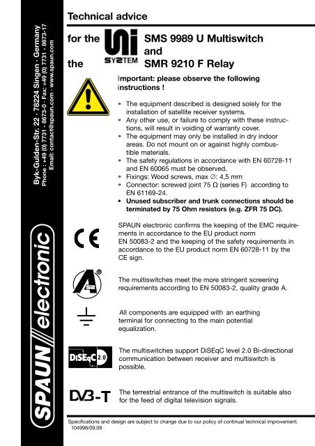
Technical advice<br />
Byk-Gulden-Str. 22 · 78224 Singen · Germany<br />
Phone : +49 (0) 7731 - 8673-0 · Fax: +49 (0) 7731 - 8673-17<br />
Email: contact@spaun.com · www.spaun.com<br />
<strong>for</strong> <strong>the</strong><br />
<strong>the</strong><br />
<strong>SMS</strong> <strong>9989</strong> U <strong>Multiswitch</strong><br />
<strong>and</strong><br />
<strong>SMR</strong> <strong>9210</strong> F <strong>Relay</strong><br />
Important: please observe <strong>the</strong> following<br />
instructions !<br />
• The equipment described is designed solely <strong>for</strong> <strong>the</strong><br />
installation of satellite receiver systems.<br />
• Any o<strong>the</strong>r use, or failure to comply with <strong>the</strong>se instructions,<br />
will result in voiding of warranty cover.<br />
• The equipment may only be installed in dry indoor<br />
areas. Do not mount on or against highly combustible<br />
materials.<br />
• The safety regulations in accordance with EN 60728-11<br />
<strong>and</strong> EN 60065 must be observed.<br />
• Fixings: Wood screws, max : 4,5 mm<br />
• Connector: screwed joint 75 (series F) according to<br />
EN 61169-24.<br />
• Unused subscriber <strong>and</strong> trunk connections should be<br />
terminated by 75 Ohm resistors (e.g. ZFR 75 DC).<br />
SPAUN electronic confirms <strong>the</strong> keeping of <strong>the</strong> EMC requirements<br />
in accordance to <strong>the</strong> EU product norm<br />
EN 50083-2 <strong>and</strong> <strong>the</strong> keeping of <strong>the</strong> safety requirements in<br />
accordance to <strong>the</strong> EU product norm EN 60728-11 by <strong>the</strong><br />
CE sign.<br />
The multiswitches meet <strong>the</strong> more stringent screening<br />
requirements according to EN 50083-2, quality grade A.<br />
All components are equipped with an earthing<br />
terminal <strong>for</strong> connecting to <strong>the</strong> main potential<br />
equalization.<br />
The multiswitches support DiSEqC level 2.0 Bi-directional<br />
communication between receiver <strong>and</strong> multiswitch is<br />
possible.<br />
-T<br />
The terrestrial entrance of <strong>the</strong> multiswitch is suitable also<br />
<strong>for</strong> <strong>the</strong> feed of digital television signals.<br />
Specifications <strong>and</strong> design are subject to change due to our policy of continual technical improvement.<br />
104998/09.09
TM<br />
Electrical <strong>and</strong> electronic equipment are not household waste - in<br />
accordance with <strong>the</strong> European directive EN 50419 (corresponds to <strong>the</strong><br />
article 11(2) of <strong>the</strong> guideline 2002/96/EC) of <strong>the</strong> European Parliament<br />
<strong>and</strong> <strong>the</strong> Council of January, 27th 2003 on used electrical <strong>and</strong> electronic<br />
equipment, it should be disposed properly.<br />
Please, on <strong>the</strong> end of its life cycle, take this unit <strong>and</strong> dispose it on designated<br />
public collection points.<br />
The permissible ambient temperature range is:<br />
-20° C ... +50° C (253 K ... 323 K).<br />
UniSystem <strong>Multiswitch</strong> <strong>SMS</strong> <strong>9989</strong> U:<br />
The multiswitch <strong>for</strong> 8 SAT IF signals <strong>and</strong> passive terrestrial is universally applicable, <strong>for</strong><br />
example:<br />
➞ As an individual device <strong>for</strong> 8 receivers,<br />
➞ As a cascadable multiswitch <strong>for</strong> an additional 8 receivers each (max. 24 receivers),<br />
➞ In a "s<strong>and</strong>wich" configuration as an add-on component to receive <strong>and</strong> distribute<br />
16 SAT IF signals (See section "Assembly instructions").<br />
Power supply:<br />
The UniSystem can be used where <strong>the</strong>re is no mains supply. The system is powered by<br />
<strong>the</strong> connected receivers. If <strong>the</strong> system is only being used by one receiver, a maximum<br />
power supply of 100 mA + LNB remote power is required. If <strong>the</strong> current output from <strong>the</strong><br />
receiver is not sufficently, you have to install an external SPAUN remote power supply<br />
at <strong>the</strong> terrestrial trunkline.<br />
LNB type:<br />
The LNB inputs of <strong>the</strong> <strong>SMS</strong> <strong>9989</strong> U multiswitch are designed <strong>for</strong> an operating voltage<br />
of 12 V. This means that Quattro LNB must be used under all circumstances.<br />
Switching logic:<br />
The SAT IF signals are selected with switching criteria 14 V / 18 V <strong>and</strong>/or 0 / 22 kHz<br />
<strong>and</strong> tone burst or with DiSEqC comm<strong>and</strong>s from <strong>the</strong> receiver.<br />
Terrestrial (5...862 MHz):<br />
The terrestrial is routed passively in <strong>the</strong> multiswitch <strong>and</strong> is return path compatible.<br />
Through loss is 4,5 dB; tap loss per receiver output is 24 dB.<br />
Terrestrial antenna signals should be fed selectively to <strong>the</strong> multiswitch in order to avoid<br />
malfunctions.
TM<br />
SAT IF (950...2200 MHz):<br />
The maximum input level is 85 dBµV at full transponder utilisation.<br />
The SAT IF signals are to be fed to <strong>the</strong> multiswitch according to <strong>the</strong> label so that<br />
<strong>the</strong> logical allocation of IF signals is correct in line with <strong>the</strong> switching criteria.<br />
• Receiver outputs A ... H / tap loss:<br />
In order to neutralise internal distribution loss, an amplifier level is integrated into<br />
<strong>the</strong> <strong>SMS</strong> <strong>9989</strong> U <strong>for</strong> every receiver output.<br />
This results in 3 ... +1 dB tap loss.<br />
The maximum output level <strong>for</strong> <strong>the</strong> SAT IF to receiver outputs A ... H is 86 dBµV.<br />
Using <strong>the</strong> changeover switch <strong>for</strong> level shifting it is possible to<br />
lower <strong>the</strong> SAT IF signal per receiver output by a maximum of<br />
12 dB in increments of 4 dB.<br />
In such a way, varying cable lengths / losses can be offset.<br />
With a cable loss of 30 dB @ 2 GHz/100 m <strong>for</strong> example, a<br />
4 dB increment corresponds to a cable length of 13 m.<br />
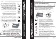
Scope of delivery:<br />
The <strong>SMS</strong> <strong>9989</strong> U multiswitch comes with:<br />
1. A mounting frame <strong>for</strong> wall <strong>and</strong> "s<strong>and</strong>wich" assembly <strong>for</strong> a system upgrade to<br />
16 SAT IF signals<br />
2. Earthing clamp.<br />
3. Nine DC-decoupled termination resistors (ZFR 75 DC) to terminate <strong>the</strong> trunkline<br />
outputs.<br />
1. 2. 3.
TM<br />
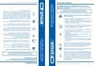
Assembly instructions:<br />
Terr.<br />
1. Receiving a SAT system with 8 SAT IF signals<br />
<strong>and</strong> terrestrial:<br />
1.1 Using <strong>the</strong> <strong>SMS</strong> <strong>9989</strong> U as a st<strong>and</strong>alone device<br />
<strong>for</strong> 8 receivers; "9 in 8" use:<br />
1.1.1 Clip <strong>the</strong> multiswitch into <strong>the</strong> mounting frame.<br />
1.1.2 Connect <strong>the</strong> outputs of <strong>the</strong> Quattro LNB with <strong>the</strong><br />
SAT IF inputs in line with <strong>the</strong> multiswitch's label.<br />
T<br />
T<br />
T<br />
T<br />
T<br />
T<br />
T<br />
T<br />
T<br />
1.1.3 Feed terrestrial signals (if available).<br />
(If not being used, terminate with 75 Ohm !)<br />
1.1.4 Establish receiver outputs A ... H . Using <strong>the</strong><br />
integrated changeover switch <strong>for</strong> level shifting,<br />
adjust various cable lengths / losses by -4 dB,<br />
-8 dB or -12 dB.<br />
(Please refer our note below).<br />
1.1.5 Terminate trunk line outputs with <strong>the</strong> DC-decoupled<br />
termination resistors included in delivery.<br />
T<br />
T<br />
T<br />
T<br />
T<br />
T<br />
T<br />
T<br />
T<br />
1.2 Using <strong>the</strong> <strong>SMS</strong> <strong>9989</strong> U in a cascade configuration<br />
<strong>for</strong> 16, max. 24 receivers:<br />
With central distribution it is possible to connect<br />
<strong>the</strong> multiswitches directly with one ano<strong>the</strong>r using<br />
ZSV 2 S quick plug connectors. They can also be<br />
installed as "floor distributors". Terminate <strong>the</strong> trunkline<br />
outputs of <strong>the</strong> last multiswitch with DC-decoupled<br />
termination resistors.<br />
General recommendation:<br />
Please note that this system may be extended to receive additional SAT systems<br />
at a later point in time.<br />
Note:<br />
You should leave all receiver cables an extra<br />
20 cm so that is possible to implement additional<br />
<strong>SMR</strong> <strong>9210</strong> F multiswitch relays later if<br />
necessary without any problems.
TM<br />
Assembly instructions:<br />
2. Receiving 4 SAT systems with 16 SAT IF<br />
signals <strong>and</strong> terrestrial:<br />
Terr.<br />
2.1 Two <strong>SMS</strong> <strong>9989</strong> U multiswitches <strong>and</strong> eight<br />
<strong>SMR</strong> <strong>9210</strong> F multiswitch relays are used<br />
<strong>for</strong> every eight receivers.<br />
2.1.1 First mount <strong>the</strong> <strong>SMS</strong> <strong>9989</strong> U multiswitch<br />
<strong>for</strong> SAT system A <strong>and</strong> B (wall assembly).<br />
2.1.2 Establish all connections (see page 4,<br />
point 1.1.1 to 1.2 as necessary).<br />
2.1.3 Carry out level adjustment on <strong>the</strong><br />
SAT system A <strong>and</strong> B multiswitch.<br />
(Please refer page 6, point 31. to 3.2).<br />
2.1.4 Clip <strong>the</strong> frame onto <strong>the</strong> mounted<br />
<strong>SMS</strong> <strong>9989</strong> U multiswitch <strong>for</strong> subsequent<br />
mounting of SAT system C <strong>and</strong> D<br />
components.<br />
2.1.5 After you have successfully completed<br />
<strong>the</strong> "s<strong>and</strong>wich" assembly, connect <strong>the</strong><br />
outputs of <strong>the</strong> Quattro LNB with <strong>the</strong> inputs<br />
of <strong>the</strong> SAT system C <strong>and</strong> D multiswitch.<br />
2.1.6 Terminate <strong>the</strong> terrestrial input <strong>and</strong> output of<br />
<strong>the</strong> second multiswitch with DC-decoupled<br />
termination resistors (ZFR 75 DC).<br />
2.1.7 Carry out level adjustment on <strong>the</strong> SAT<br />
system C <strong>and</strong> D multiswitch.<br />
(Please refer page 6, point 31. to 3.2).<br />
2.1.8 Receiver outputs of both multiswitches<br />
are combined by attaching <strong>the</strong> <strong>SMR</strong> <strong>9210</strong> F<br />
multiswitch relays. Once <strong>the</strong> receiver cables<br />
have been connected to <strong>the</strong> receivers,<br />
program selection is possible from 16 SAT IF<br />
signals.<br />
2.2 Using <strong>the</strong> multiswitch system in a cascade<br />
configuration <strong>for</strong> 16, max. 24 receivers<br />
(see page 4, point 1.2).
TM<br />
Assembly instructions:<br />
Terr.<br />
Terr.<br />
3. Adjusting <strong>the</strong> SAT-Systems A / B <strong>and</strong> C / D<br />
with SAT attenuator unit SDE 4415/5 F<br />
(Order No. 871319)<br />
3.1 The SAT attenuator unit SDE 4415/5 F can be used<br />
<strong>for</strong> adjusting / balancing different signals between<br />
<strong>the</strong> satellite systems. The unit can be attached directly<br />
onto <strong>the</strong> input of SAT system A or B <strong>and</strong><br />
C or D of <strong>the</strong> multiswitch <strong>SMS</strong> <strong>9989</strong> U.<br />
The loss value is fixed 5 dB.<br />
3.2 The usage of <strong>the</strong> SAT attenuator SDE 4415/5 F<br />
depends on <strong>the</strong> incoming level of <strong>the</strong> satellite<br />
signals. If <strong>the</strong> level is higher than 85 dBµV (please<br />
refer page 3), you should use <strong>the</strong> SAT attenuator<br />
SDE 4415/5 F. Also you should use <strong>the</strong> unit, if <strong>the</strong><br />
difference between <strong>the</strong> two satellite systems A / B<br />
or C / D is higher than 5 dB.<br />
SDE 4415/5 F